EP0338422A2 - Méthode, outil de transfert, pousseur et magasin de cales pour l'insertion de bobines dans les stators de moteurs électriques - Google Patents
Méthode, outil de transfert, pousseur et magasin de cales pour l'insertion de bobines dans les stators de moteurs électriques Download PDFInfo
- Publication number
- EP0338422A2 EP0338422A2 EP89106590A EP89106590A EP0338422A2 EP 0338422 A2 EP0338422 A2 EP 0338422A2 EP 89106590 A EP89106590 A EP 89106590A EP 89106590 A EP89106590 A EP 89106590A EP 0338422 A2 EP0338422 A2 EP 0338422A2
- Authority
- EP
- European Patent Office
- Prior art keywords
- tool
- strips
- cover
- stator
- tubular shaft
- Prior art date
- Legal status (The legal status is an assumption and is not a legal conclusion. Google has not performed a legal analysis and makes no representation as to the accuracy of the status listed.)
- Withdrawn
Links
Images
Classifications
-
- H—ELECTRICITY
- H02—GENERATION; CONVERSION OR DISTRIBUTION OF ELECTRIC POWER
- H02K—DYNAMO-ELECTRIC MACHINES
- H02K15/00—Processes or apparatus specially adapted for manufacturing, assembling, maintaining or repairing of dynamo-electric machines
- H02K15/06—Embedding prefabricated windings in the machines
- H02K15/062—Windings in slots; Salient pole windings
- H02K15/065—Windings consisting of complete sections, e.g. coils or waves
- H02K15/067—Windings consisting of complete sections, e.g. coils or waves inserted in parallel to the axis of the slots or inter-polar channels
- H02K15/068—Strippers; Embedding windings by strippers
-
- H—ELECTRICITY
- H02—GENERATION; CONVERSION OR DISTRIBUTION OF ELECTRIC POWER
- H02K—DYNAMO-ELECTRIC MACHINES
- H02K15/00—Processes or apparatus specially adapted for manufacturing, assembling, maintaining or repairing of dynamo-electric machines
- H02K15/06—Embedding prefabricated windings in the machines
- H02K15/062—Windings in slots; Salient pole windings
- H02K15/065—Windings consisting of complete sections, e.g. coils or waves
- H02K15/067—Windings consisting of complete sections, e.g. coils or waves inserted in parallel to the axis of the slots or inter-polar channels
-
- Y—GENERAL TAGGING OF NEW TECHNOLOGICAL DEVELOPMENTS; GENERAL TAGGING OF CROSS-SECTIONAL TECHNOLOGIES SPANNING OVER SEVERAL SECTIONS OF THE IPC; TECHNICAL SUBJECTS COVERED BY FORMER USPC CROSS-REFERENCE ART COLLECTIONS [XRACs] AND DIGESTS
- Y10—TECHNICAL SUBJECTS COVERED BY FORMER USPC
- Y10T—TECHNICAL SUBJECTS COVERED BY FORMER US CLASSIFICATION
- Y10T29/00—Metal working
- Y10T29/49—Method of mechanical manufacture
- Y10T29/49002—Electrical device making
- Y10T29/49009—Dynamoelectric machine
-
- Y—GENERAL TAGGING OF NEW TECHNOLOGICAL DEVELOPMENTS; GENERAL TAGGING OF CROSS-SECTIONAL TECHNOLOGIES SPANNING OVER SEVERAL SECTIONS OF THE IPC; TECHNICAL SUBJECTS COVERED BY FORMER USPC CROSS-REFERENCE ART COLLECTIONS [XRACs] AND DIGESTS
- Y10—TECHNICAL SUBJECTS COVERED BY FORMER USPC
- Y10T—TECHNICAL SUBJECTS COVERED BY FORMER US CLASSIFICATION
- Y10T29/00—Metal working
- Y10T29/49—Method of mechanical manufacture
- Y10T29/49002—Electrical device making
- Y10T29/4902—Electromagnet, transformer or inductor
- Y10T29/49073—Electromagnet, transformer or inductor by assembling coil and core
-
- Y—GENERAL TAGGING OF NEW TECHNOLOGICAL DEVELOPMENTS; GENERAL TAGGING OF CROSS-SECTIONAL TECHNOLOGIES SPANNING OVER SEVERAL SECTIONS OF THE IPC; TECHNICAL SUBJECTS COVERED BY FORMER USPC CROSS-REFERENCE ART COLLECTIONS [XRACs] AND DIGESTS
- Y10—TECHNICAL SUBJECTS COVERED BY FORMER USPC
- Y10T—TECHNICAL SUBJECTS COVERED BY FORMER US CLASSIFICATION
- Y10T29/00—Metal working
- Y10T29/53—Means to assemble or disassemble
- Y10T29/5313—Means to assemble electrical device
- Y10T29/53143—Motor or generator
- Y10T29/53152—Means to position insulation
-
- Y—GENERAL TAGGING OF NEW TECHNOLOGICAL DEVELOPMENTS; GENERAL TAGGING OF CROSS-SECTIONAL TECHNOLOGIES SPANNING OVER SEVERAL SECTIONS OF THE IPC; TECHNICAL SUBJECTS COVERED BY FORMER USPC CROSS-REFERENCE ART COLLECTIONS [XRACs] AND DIGESTS
- Y10—TECHNICAL SUBJECTS COVERED BY FORMER USPC
- Y10T—TECHNICAL SUBJECTS COVERED BY FORMER US CLASSIFICATION
- Y10T29/00—Metal working
- Y10T29/53—Means to assemble or disassemble
- Y10T29/5313—Means to assemble electrical device
- Y10T29/53143—Motor or generator
- Y10T29/53161—Motor or generator including deforming means
Definitions
- the invention relates to a method for pulling coils into stators of electric motors using an insertion tool consisting of insertion strips, each of which has two tongues that expand elastically from one another and are inserted with the correct polarity in a disk-shaped support arrangement which has a coaxial shaft, and using a shaping tool which is fixed on a tubular shaft which can be displaced on the shaft and which engages the coil heads, the stator provided with a slot insulation being fixed by a clamping device.
- German Patent 34 09 684 A method of this type is known from German Patent 34 09 684. This can be assumed with the proviso that plastic insert with metal guide lamellae, as described in German patent 35 01 879, are used as the insertion strips.
- the insertion tool with the still empty insertion strips is first inserted a little into the vertical stator. Then the bobbins to be drawn in are threaded between the spread tongue tips of the insertion bars thus fixed.
- the shaping tool used has radial driver arms which rest against the coil heads with their radial surface or with a front face that is slightly slanted relative to the radial plane.
- the invention has for its object to facilitate the winding of the bobbins and to reduce the time required for this and to prevent damage to the bobbins even better.
- a transformer tool is added to the tools used hitherto, which, due to the long and narrow shape of its transmission forks, forces the flat shape of the coils, ie an elongated, narrow overall copper cross section at least of the coil sides parallel to the winding axis.
- the transfer tool is used to transport the coils from the place of their manufacture on the winding machine to the insertion tool or to the stator.
- the coils to be drawn in in one thrust are thus transferred together from the transfer tool to the insertion tool, at least the preparatory actions, namely the joining of the two tools outside of the stator takes place or at least can be done, whereby this plugging is facilitated due to all-round accessibility.
- the insertion tool is then inserted into the stator together with the transfer tool, and in such a way that the guide lamellae of the tongue still protrude a little from the stator, the coils are fully inserted into the insertion strips and a little into the stator slots. Due to the flat shape of the coils, the force required for the pull-in process is considerably lower than before. Rejects due to coil injuries practically no longer occur.
- Another advantage of the invention which should not be underestimated, is that the workflow is improved in the series re-winding of stators and enables a division into individual work by separating the winding and filling of a large number of transfer tools as preparatory work from the actual pulling-in process.
- the further proposals relate to expedient training of the tools that can be used to carry out the method according to the invention, in particular the transfer tool and the cover strip magazine.
- the transfer tool and the cover strip magazine Like the insertion tool used for stators with different diameters, number of holes and types of winding, these can be changed and adapted.
- these tools consist of individual parts which can be fastened to uniformly constructed support arrangements with the aid of uniform fastening means.
- the individual support arrangement consisting of a circular cylindrical disc with a circumferential collar on the lateral surface, with a perforated disc being attached to each side, corresponds to the support arrangement of the known insertion tool.
- the disc diameter and possibly the number of holes are sensibly graded in order to be able to detect stators with as many different dimensions as possible.
- the transfer forks are the components of the transfer tools and the guide channels are the components of the cover slide magazines.
- the respective fastening projections which have the same shape throughout, correspond in shape to the foot parts of the known insertion strips.
- the tools mentioned thus form a system of work equipment that is characterized by an extraordinarily wide range of applications and low investment costs. This can be seen, for example, from the fact that the support arrangements for the three when working on a stator cooperating tools have three different diameters, so that the support assemblies need only be present once in each size.
- An essential feature of the transmission forks is that the distance between the two parallel fork tines corresponds approximately to the slot width of the stator. As a result, the coil sides with such a flat cross-sectional shape are taken into the insertion strips that they can be pulled through the slot slots easily and without damage in this shape.
- the shaping tool proposed herewith is characterized in that axial projections are provided on a thrust plate with slots formed in between and open on the side facing away from the thrust plate.
- the flat-shaped coil heads are received by these slots and preferably firmly enclosed.
- a cover plate parallel to the impact plate is used for this. At its edge, this can also have axial guides for the tongue ends of the insertion strips, which facilitates the plugging together of the transfer tool and the insertion tool.
- the guide channels of the cover strip magazines preferably have a square cross section and are chamfered at the ends, so that the cover strips can be inserted easily and the front end of which is fully visible.
- the guide channels are preferably at least as long as the spread tongue sections the insertion strips, but much shorter than the cover strips.
- An arrangement of the guide channels slightly converging towards the stator facilitates the insertion of the cover strips.
- a guide nose pointing to the stator axis can be attached to at least one tongue. This can cooperate with a wedge-shaped guide groove on the lateral surface of the aforementioned cover plate of the shaping tool.
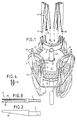
- the devices shown are used to wind the stator of a six-pole three-phase motor with two-hole winding.
- the stator 1 indicated in FIG. 10 has thirty-six slots and three pairs of concentric coils 2 and 3 (FIGS. 1 and 9) per phase, which are introduced together.
- the insertion tool 4 which is known in principle, consists of a support arrangement 5 and a series of insertion strips, the latter consisting of two parallel tongues 6 made of a relatively elastic plastic, which have a common molded base 7 of rectangular cross section. At the foot part is a rectangular one Cross groove attached. Guide blades 8 made of thin spring steel are embedded in the tongues. They extend over the parallel central section of the tongues and cover the tooth heads. The front, wedge-shaped sections of the tongues 6 are slightly spread apart (FIG. 1). On one tongue tip of a insertion bar there is a suppository 9 on the outside and a hole 10 on the other tongue tip so that the adjacent tongue tips of adjacent insertion bars can be clipped together. Furthermore, every second insertion strip has a guide lug 11 pointing radially inwards with respect to the stator at a tip of the tongue.
- the support arrangement 5 consists of two identical perforated disks 12, which receive a thicker disk 13 with a rectangular collar 14 on the lateral surface between them.
- the perforated disks each have a ring of thirty-six rectangular holes 15 which fit together with the foot parts 7.
- the foot parts are first inserted through the right-hand perforated disc and pushed in an inclined position over the collar 14, so that it falls into the transverse groove.
- the second perforated disc is put on and the package is held together by means of a screw connection and firmly connected to a coaxial shaft 16.
- the number and arrangement of the insert strips on the perforated ring depends on the application. In the example, twelve insert strips are arranged in pairs evenly distributed over the circumference. To simplify the drawing, only one insert bar is shown in FIGS. 9 to 11.
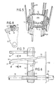
- the transfer tool according to FIGS. 1 to 4 consists of the same support arrangement 5 and of twelve transfer forks 17, which are made of metal by die-casting and are provided with a hard, polished surface. These transmission forks have two parallel flat tines 18 which taper in a wedge shape towards the tip and which are spherically shaped on the inside or rounded on the inside edges. The slot 19 between the fork tines is approximately the same width as the slot slots of the stator 1.
- the fork stem is formed by a foot part 7 of the same shape as in the insertion strips.
- the twelve transmitter forks 17 shown are attached to the support arrangement in the same distribution and in the same way as described for the insertion strips.
- the support arrangement is slidably mounted on a tubular shaft 20, the three disks must be held together in the axial direction here, which can be done, for example, by two screws which reach through unoccupied holes.
- a clamping screw radially penetrating the disk 13 can be provided.
- the shaping tool is explained with reference to FIGS. 1 and 9. It has a thrust plate 21 which is fastened coaxially to the aforementioned tubular shaft 20 by means of two spring rings 22.
- a total of six sharpened pins are arranged on the upper or, in relation to the pulling-in direction, front side, in pairs a thicker pin 23 and a thinner pin 24. These pins sit on three radii, each offset by 120 °, near the edge of the disk and extend axially. The distance between the pins corresponds in magnitude to the distance between the fork prongs 18.
- a cover plate 25, not shown in FIG. 1, is placed on the pins, the outer diameter of which corresponds to the inner diameter of the pull-in rim.
- the cover plate has six holes 26 so that it can be inserted over the pins 23 and 24 and thereby closes the slot formed between two pins.
- the cover plate also serves to guide the respectively connected tongue tips of the insertion strips and for this purpose has six guide grooves 27 which open wide towards the front and which cooperate with the guide lugs 11 on their lateral surface. Such a guide groove 27 is shown as an example in FIGS. 9 and 10.
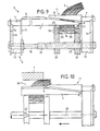
- Figures 5 to 8 show a cover slide magazine.
- the support arrangement 5 is used again, but covered with twelve guide channels 28, which are produced as injection molded plastic parts. These guide channels also have the same base parts 7.
- the support arrangement can be moved on the tubular shaft 20.
- the clear channel cross section 29 is square and approximately designed for the dimensions of the cover slide 30.
- the channel openings are formed in the guide channels 28 in such a way that the inserted cover slides 30 are slightly inclined towards the central axis of the support arrangement.
- the channel openings are chamfered.
- Fig. 6 also shows a thrust plate 32 with a clamping collar 33, which can also be attached to the tubular shaft 20 and the diameter of which is so large that the free ends of the cover slide ring can be gripped.
- the transformer tool according to FIG. 1 is equipped with the coils.
- the pusher tool is already inserted into the transmitter tool so that the pusher plate 21 abuts the fork-side perforated disk 12 and is angularly oriented so that the pairs of pins 23, 24 are each centered between the pairs of transmitter forks 17.
- the inner coil 2 of each concentric coil pair is threaded into the two mutually adjacent transmission forks 17 and between the pins 23 and 24 as shown in FIG. 1.
- the coils have or get an extremely flat "ribbon" cross-section since they are gripped three times.
- the respective coil 3 is inserted into the subsequent transmission forks 17 and placed around the pin 23.
- a further pin could also be attached so that these coils would also be held in the center of the coil head.
- a cover disk 25 is placed on the bobbin heads and the pins.
- a rubber band 34 can be wrapped around the coil sides for the same purpose.
- the so-equipped transducer and butting tool is assembled with the insertion tool by pushing the tubular shaft 20 with the transducer forks 17 onto the shaft 16.
- the clipped tongue ends of the insertion tool travel between the coils 2 and 3, the guide lugs 11 being guided by the guide grooves 27 on the cover plate 25, which is advantageous in this respect and simplifies the assembly because the insertion strips have a certain instability and cannot be aligned with millimeter precision.
- Fig. 9 shows the assembled tools, for the better Clarity only the coil 2 is shown.
- the guide forks 18 stand radially on the outside over the spread sections of the insertion strips.
- the tongue tips abut the front perforated disk 12 of the transfer tool.
- the flat cross section 35 of the coil 2 is enclosed between the pins 23 and 24 and the plates 21 and 25.
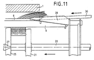
- a second stroke which can also be connected to the first one without interruption, brings the tubular shaft 20 to a stop and from there the impact tool with the coils moves together with the insertion tool relative to the stator 1.
- This movement initially ends with the position according to FIG 11.
- the coil sides now swell out of the stator slot openings with a full copper cross section and the guide fins 8 of the insertion strips are immersed along the entire length behind the stator front surface. This is the position for attaching the cover strips 30.
- the filled one is now used Cover strip magazine placed on the tubular shaft 20 until the guide channels 28 abut against the stator front surface.
- stator inner diameter is 104 mm.
- the carrying arrangements of the various tools are graduated in diameter, namely the outer disk diameter is 103 mm for the insertion tool, 115 mm for the transfer tool and 110 mm for the cover strip magazine.
- the tubular shaft 20 is moved in the example, but in particular in the case of stators of larger diameter, by means of a power drive which can be actuated by a foot switch, so that the worker has his hands free.
- Electrically driven lifting spindles have proven their worth, but also hydraulically or pneumatically actuated cylinders.
Landscapes
- Engineering & Computer Science (AREA)
- Manufacturing & Machinery (AREA)
- Power Engineering (AREA)
- Manufacture Of Motors, Generators (AREA)
Applications Claiming Priority (2)
| Application Number | Priority Date | Filing Date | Title |
|---|---|---|---|
| DE3812726A DE3812726A1 (de) | 1988-04-16 | 1988-04-16 | Vorrichtung zum einziehen von spulen in statoren von elektromotoren |
| DE3812726 | 1988-04-16 |
Publications (2)
| Publication Number | Publication Date |
|---|---|
| EP0338422A2 true EP0338422A2 (fr) | 1989-10-25 |
| EP0338422A3 EP0338422A3 (fr) | 1990-07-04 |
Family
ID=6352142
Family Applications (1)
| Application Number | Title | Priority Date | Filing Date |
|---|---|---|---|
| EP89106590A Withdrawn EP0338422A3 (fr) | 1988-04-16 | 1989-04-13 | Méthode, outil de transfert, pousseur et magasin de cales pour l'insertion de bobines dans les stators de moteurs électriques |
Country Status (3)
| Country | Link |
|---|---|
| US (1) | US5010639A (fr) |
| EP (1) | EP0338422A3 (fr) |
| DE (1) | DE3812726A1 (fr) |
Cited By (1)
| Publication number | Priority date | Publication date | Assignee | Title |
|---|---|---|---|---|
| CN103441616A (zh) * | 2013-08-22 | 2013-12-11 | 嘉兴格鲁博机械有限公司 | 一种膨胀式嵌入电机副相线圈及槽楔的方法及装置 |
Families Citing this family (6)
| Publication number | Priority date | Publication date | Assignee | Title |
|---|---|---|---|---|
| US5714824A (en) * | 1994-06-23 | 1998-02-03 | Hydro-Quebec | Conductor section for a stator frame of a polyphase dynamoelectric machine |
| DE19736645C2 (de) * | 1997-08-22 | 1999-12-02 | Gruendl & Hoffmann | Wanderfeldmaschine |
| JP4096908B2 (ja) * | 2004-03-31 | 2008-06-04 | 株式会社豊田自動織機 | 回転電機の製造方法 |
| DE102014009799A1 (de) * | 2014-07-03 | 2016-01-07 | Audi Ag | Verfahren und Vorrichtung zur Herstellung einer Elektromaschine |
| JP6985165B2 (ja) * | 2018-01-29 | 2021-12-22 | Dowaエコシステム株式会社 | 巻線分離装置および巻線分離方法 |
| CN116865506B (zh) * | 2023-06-30 | 2024-08-30 | 深圳市金岷江智能装备有限公司 | 插线装置及电机加工设备 |
Family Cites Families (8)
| Publication number | Priority date | Publication date | Assignee | Title |
|---|---|---|---|---|
| DE1919433C3 (de) * | 1969-04-17 | 1974-07-25 | Balzer & Droell Kg, 6369 Niederdorfelden | Vorrichtung zum Wickeln von Spulen für elektrische Maschinen |
| US3672026A (en) * | 1970-05-11 | 1972-06-27 | Gen Electric | Apparatus for developing wound coils for electromagnetic devices |
| DE2443380A1 (de) * | 1974-09-11 | 1976-04-01 | Veser F | Verfahren und vorrichtung zum einziehen vorgewickelter spulen |
| DE3209621A1 (de) * | 1982-03-17 | 1983-09-29 | Franz 7980 Ravensburg Veser | Verfahren und einrichtungen zum herstellen, zurichten und einbringen von spulensaetzen fuer statoren elektrischer maschinen |
| DE3409684C1 (de) * | 1984-03-16 | 1985-10-10 | Franz 7980 Ravensburg Veser | Verfahren,Einziehwerkzeug,Einziehnadel und Fixierstern zum Einziehen von Spulen in Statoren von Elektromotoren |
| DE3501879C1 (de) * | 1985-01-22 | 1986-07-31 | Franz 7980 Ravensburg Veser | Spuleneinbringleiste fuer Statoren elektrischer Maschinen |
| JP2839830B2 (ja) * | 1985-10-24 | 1998-12-16 | テキサス インスツルメンツ インコーポレイテツド | 集積回路の製造方法 |
| US4800646A (en) * | 1987-09-24 | 1989-01-31 | Pease Windamatic Systems, Inc. | Transfer tooling for wire coils |
-
1988
- 1988-04-16 DE DE3812726A patent/DE3812726A1/de active Granted
-
1989
- 1989-04-13 EP EP89106590A patent/EP0338422A3/fr not_active Withdrawn
- 1989-04-14 US US07/337,946 patent/US5010639A/en not_active Expired - Fee Related
Cited By (2)
| Publication number | Priority date | Publication date | Assignee | Title |
|---|---|---|---|---|
| CN103441616A (zh) * | 2013-08-22 | 2013-12-11 | 嘉兴格鲁博机械有限公司 | 一种膨胀式嵌入电机副相线圈及槽楔的方法及装置 |
| CN103441616B (zh) * | 2013-08-22 | 2015-08-19 | 嘉兴格鲁博机械有限公司 | 一种膨胀式嵌入电机副相线圈及槽楔的方法及装置 |
Also Published As
| Publication number | Publication date |
|---|---|
| DE3812726C2 (fr) | 1990-01-18 |
| EP0338422A3 (fr) | 1990-07-04 |
| DE3812726A1 (de) | 1989-10-26 |
| US5010639A (en) | 1991-04-30 |
Similar Documents
| Publication | Publication Date | Title |
|---|---|---|
| DE2630183C3 (de) | Vorrichtung zum Einziehen von Wicklungen in Nuten von Statoren von Elektromotoren | |
| DE3013011C2 (de) | Verfahren zum Anordnen von Wickelkopfisolierabschnitten im Stator einer elektrischen Maschine und Vorrichtung zur Durchführung des Verfahrens | |
| DE3114407C2 (fr) | ||
| DE2001677B2 (de) | Vorrichtung zum Einziehen von Spulen in die Nuten eines Stators elektrischer Maschinen | |
| DE2808048A1 (de) | Vorrichtung zum wickeln von spulen fuer statoren elektrischer maschinen | |
| DE1764196B2 (de) | Preßvorrichtung zur Herstellung von vorzugsgerichteten Dauermagneten | |
| DE3051021C2 (fr) | ||
| DE2043607A1 (de) | Vorrichtung zur Formung von Wick lungskopfen | |
| EP0338422A2 (fr) | Méthode, outil de transfert, pousseur et magasin de cales pour l'insertion de bobines dans les stators de moteurs électriques | |
| DE2116994C3 (de) | Zusammenklappbarer zylindrischer Kern zum Vulkanisieren von endlosen Riemen | |
| EP0111687B1 (fr) | Méthode de fabrication d'une bague de segments de commutateur | |
| DE4126655C1 (fr) | ||
| DE4300764C2 (de) | Verfahren und Vorrichtung zur Herstellung einer Wellenwicklung | |
| DD218505A5 (de) | Verfahren und vorrichtung zum formen und einbringen von feldwicklungen in elektrischen maschinen | |
| DE3334680C2 (de) | Verfahren zum Einsetzen von Spulen in Nuten eines Statorblechpakets und Spulen-Einsetzvorrichtung | |
| EP0188776A2 (fr) | Dispositif de transfert pour le transport pas à pas de materiau et/ou de pièce à usiner, particulièrement dans les presses | |
| DE2309837C3 (de) | Vorrichtung zum Abstreifen von Drahtspulen für elektrische Maschinen von einer Wickelschablone | |
| DE2344193A1 (de) | Verfahren zum herstellen eines stators fuer elektrische maschinen | |
| DE3409684C1 (de) | Verfahren,Einziehwerkzeug,Einziehnadel und Fixierstern zum Einziehen von Spulen in Statoren von Elektromotoren | |
| DE4239465A1 (fr) | ||
| DE3218132A1 (de) | Verfahren und vorrichtung zum stanzen von wenigstens zwei zueinander koaxialen blechteilen | |
| DE381719C (de) | Stromwender mit metallischer Tragbuechse fuer elektrische Maschinen | |
| DE517085C (de) | Magnetelektrische Lampe mit einem mehrteiligen, aus Isolierstoff bestehenden Gehaeuse | |
| DE2712755C2 (de) | Vorrichtung zum Einziehen von Wicklungen in Nuten von Statoren von Elektromotoren | |
| DE3143712A1 (de) | Vorrichtung zur herstellung von geschweissten gittern |
Legal Events
| Date | Code | Title | Description |
|---|---|---|---|
| PUAI | Public reference made under article 153(3) epc to a published international application that has entered the european phase |
Free format text: ORIGINAL CODE: 0009012 |
|
| AK | Designated contracting states |
Kind code of ref document: A2 Designated state(s): AT BE CH DE ES FR GB GR IT LI LU NL SE |
|
| RBV | Designated contracting states (corrected) |
Designated state(s): DE FR GB IT |
|
| PUAL | Search report despatched |
Free format text: ORIGINAL CODE: 0009013 |
|
| AK | Designated contracting states |
Kind code of ref document: A3 Designated state(s): DE FR GB IT |
|
| RBV | Designated contracting states (corrected) |
Designated state(s): FR GB IT |
|
| REG | Reference to a national code |
Ref country code: DE Ref legal event code: 8566 |
|
| 17P | Request for examination filed |
Effective date: 19901006 |
|
| 17Q | First examination report despatched |
Effective date: 19930216 |
|
| STAA | Information on the status of an ep patent application or granted ep patent |
Free format text: STATUS: THE APPLICATION IS DEEMED TO BE WITHDRAWN |
|
| 18D | Application deemed to be withdrawn |
Effective date: 19930810 |