EP0337674B1 - Verfahren zum Auskleiden einer Leitung mit einem starren Rohr - Google Patents
Verfahren zum Auskleiden einer Leitung mit einem starren Rohr Download PDFInfo
- Publication number
- EP0337674B1 EP0337674B1 EP89303455A EP89303455A EP0337674B1 EP 0337674 B1 EP0337674 B1 EP 0337674B1 EP 89303455 A EP89303455 A EP 89303455A EP 89303455 A EP89303455 A EP 89303455A EP 0337674 B1 EP0337674 B1 EP 0337674B1
- Authority
- EP
- European Patent Office
- Prior art keywords
- tube
- bores
- lining
- rigid
- wall thickness
- Prior art date
- Legal status (The legal status is an assumption and is not a legal conclusion. Google has not performed a legal analysis and makes no representation as to the accuracy of the status listed.)
- Expired - Lifetime
Links
- 238000000034 method Methods 0.000 title claims description 36
- 238000010438 heat treatment Methods 0.000 claims description 37
- 239000004033 plastic Substances 0.000 claims description 27
- 229920003023 plastic Polymers 0.000 claims description 27
- 239000012530 fluid Substances 0.000 claims description 24
- 230000002093 peripheral effect Effects 0.000 description 8
- XLYOFNOQVPJJNP-UHFFFAOYSA-N water Substances O XLYOFNOQVPJJNP-UHFFFAOYSA-N 0.000 description 5
- -1 polyethylene Polymers 0.000 description 4
- 239000004698 Polyethylene Substances 0.000 description 2
- 239000004743 Polypropylene Substances 0.000 description 2
- 238000001816 cooling Methods 0.000 description 2
- 238000007599 discharging Methods 0.000 description 2
- 238000005192 partition Methods 0.000 description 2
- 229920000573 polyethylene Polymers 0.000 description 2
- 229920001155 polypropylene Polymers 0.000 description 2
- 239000007787 solid Substances 0.000 description 2
- 239000000853 adhesive Substances 0.000 description 1
- 230000001070 adhesive effect Effects 0.000 description 1
- 230000002411 adverse Effects 0.000 description 1
- 230000005494 condensation Effects 0.000 description 1
- 238000009833 condensation Methods 0.000 description 1
- 239000012809 cooling fluid Substances 0.000 description 1
- 230000001419 dependent effect Effects 0.000 description 1
- 230000000694 effects Effects 0.000 description 1
- 238000002474 experimental method Methods 0.000 description 1
- 230000002349 favourable effect Effects 0.000 description 1
- 238000004519 manufacturing process Methods 0.000 description 1
- 239000000463 material Substances 0.000 description 1
- 238000002844 melting Methods 0.000 description 1
- 230000008018 melting Effects 0.000 description 1
- 229920000915 polyvinyl chloride Polymers 0.000 description 1
- 239000004800 polyvinyl chloride Substances 0.000 description 1
- 239000002689 soil Substances 0.000 description 1
- 229920001169 thermoplastic Polymers 0.000 description 1
- 239000004416 thermosoftening plastic Substances 0.000 description 1
- 239000011800 void material Substances 0.000 description 1
Images
Classifications
-
- B—PERFORMING OPERATIONS; TRANSPORTING
- B29—WORKING OF PLASTICS; WORKING OF SUBSTANCES IN A PLASTIC STATE IN GENERAL
- B29C—SHAPING OR JOINING OF PLASTICS; SHAPING OF MATERIAL IN A PLASTIC STATE, NOT OTHERWISE PROVIDED FOR; AFTER-TREATMENT OF THE SHAPED PRODUCTS, e.g. REPAIRING
- B29C63/00—Lining or sheathing, i.e. applying preformed layers or sheathings of plastics; Apparatus therefor
- B29C63/26—Lining or sheathing of internal surfaces
- B29C63/34—Lining or sheathing of internal surfaces using tubular layers or sheathings
-
- F—MECHANICAL ENGINEERING; LIGHTING; HEATING; WEAPONS; BLASTING
- F16—ENGINEERING ELEMENTS AND UNITS; GENERAL MEASURES FOR PRODUCING AND MAINTAINING EFFECTIVE FUNCTIONING OF MACHINES OR INSTALLATIONS; THERMAL INSULATION IN GENERAL
- F16L—PIPES; JOINTS OR FITTINGS FOR PIPES; SUPPORTS FOR PIPES, CABLES OR PROTECTIVE TUBING; MEANS FOR THERMAL INSULATION IN GENERAL
- F16L58/00—Protection of pipes or pipe fittings against corrosion or incrustation
- F16L58/02—Protection of pipes or pipe fittings against corrosion or incrustation by means of internal or external coatings
- F16L58/04—Coatings characterised by the materials used
- F16L58/10—Coatings characterised by the materials used by rubber or plastics
- F16L58/1009—Coatings characterised by the materials used by rubber or plastics the coating being placed inside the pipe
- F16L58/1027—Coatings characterised by the materials used by rubber or plastics the coating being placed inside the pipe the coating being a sprayed layer
-
- B—PERFORMING OPERATIONS; TRANSPORTING
- B29—WORKING OF PLASTICS; WORKING OF SUBSTANCES IN A PLASTIC STATE IN GENERAL
- B29B—PREPARATION OR PRETREATMENT OF THE MATERIAL TO BE SHAPED; MAKING GRANULES OR PREFORMS; RECOVERY OF PLASTICS OR OTHER CONSTITUENTS OF WASTE MATERIAL CONTAINING PLASTICS
- B29B13/00—Conditioning or physical treatment of the material to be shaped
- B29B13/02—Conditioning or physical treatment of the material to be shaped by heating
- B29B13/023—Half-products, e.g. films, plates
- B29B13/024—Hollow bodies, e.g. tubes or profiles
-
- B—PERFORMING OPERATIONS; TRANSPORTING
- B29—WORKING OF PLASTICS; WORKING OF SUBSTANCES IN A PLASTIC STATE IN GENERAL
- B29C—SHAPING OR JOINING OF PLASTICS; SHAPING OF MATERIAL IN A PLASTIC STATE, NOT OTHERWISE PROVIDED FOR; AFTER-TREATMENT OF THE SHAPED PRODUCTS, e.g. REPAIRING
- B29C49/00—Blow-moulding, i.e. blowing a preform or parison to a desired shape within a mould; Apparatus therefor
- B29C49/24—Lining or labelling
- B29C49/26—Lining or labelling inner lining of tubes
-
- F—MECHANICAL ENGINEERING; LIGHTING; HEATING; WEAPONS; BLASTING
- F16—ENGINEERING ELEMENTS AND UNITS; GENERAL MEASURES FOR PRODUCING AND MAINTAINING EFFECTIVE FUNCTIONING OF MACHINES OR INSTALLATIONS; THERMAL INSULATION IN GENERAL
- F16L—PIPES; JOINTS OR FITTINGS FOR PIPES; SUPPORTS FOR PIPES, CABLES OR PROTECTIVE TUBING; MEANS FOR THERMAL INSULATION IN GENERAL
- F16L58/00—Protection of pipes or pipe fittings against corrosion or incrustation
- F16L58/02—Protection of pipes or pipe fittings against corrosion or incrustation by means of internal or external coatings
-
- B—PERFORMING OPERATIONS; TRANSPORTING
- B29—WORKING OF PLASTICS; WORKING OF SUBSTANCES IN A PLASTIC STATE IN GENERAL
- B29C—SHAPING OR JOINING OF PLASTICS; SHAPING OF MATERIAL IN A PLASTIC STATE, NOT OTHERWISE PROVIDED FOR; AFTER-TREATMENT OF THE SHAPED PRODUCTS, e.g. REPAIRING
- B29C2949/00—Indexing scheme relating to blow-moulding
- B29C2949/07—Preforms or parisons characterised by their configuration
- B29C2949/079—Auxiliary parts or inserts
- B29C2949/08—Preforms made of several individual parts, e.g. by welding or gluing parts together
-
- B—PERFORMING OPERATIONS; TRANSPORTING
- B29—WORKING OF PLASTICS; WORKING OF SUBSTANCES IN A PLASTIC STATE IN GENERAL
- B29C—SHAPING OR JOINING OF PLASTICS; SHAPING OF MATERIAL IN A PLASTIC STATE, NOT OTHERWISE PROVIDED FOR; AFTER-TREATMENT OF THE SHAPED PRODUCTS, e.g. REPAIRING
- B29C35/00—Heating, cooling or curing, e.g. crosslinking or vulcanising; Apparatus therefor
- B29C35/02—Heating or curing, e.g. crosslinking or vulcanizing during moulding, e.g. in a mould
- B29C35/04—Heating or curing, e.g. crosslinking or vulcanizing during moulding, e.g. in a mould using liquids, gas or steam
-
- B—PERFORMING OPERATIONS; TRANSPORTING
- B29—WORKING OF PLASTICS; WORKING OF SUBSTANCES IN A PLASTIC STATE IN GENERAL
- B29C—SHAPING OR JOINING OF PLASTICS; SHAPING OF MATERIAL IN A PLASTIC STATE, NOT OTHERWISE PROVIDED FOR; AFTER-TREATMENT OF THE SHAPED PRODUCTS, e.g. REPAIRING
- B29C35/00—Heating, cooling or curing, e.g. crosslinking or vulcanising; Apparatus therefor
- B29C35/02—Heating or curing, e.g. crosslinking or vulcanizing during moulding, e.g. in a mould
- B29C35/04—Heating or curing, e.g. crosslinking or vulcanizing during moulding, e.g. in a mould using liquids, gas or steam
- B29C35/049—Heating or curing, e.g. crosslinking or vulcanizing during moulding, e.g. in a mould using liquids, gas or steam using steam or damp
-
- B—PERFORMING OPERATIONS; TRANSPORTING
- B29—WORKING OF PLASTICS; WORKING OF SUBSTANCES IN A PLASTIC STATE IN GENERAL
- B29K—INDEXING SCHEME ASSOCIATED WITH SUBCLASSES B29B, B29C OR B29D, RELATING TO MOULDING MATERIALS OR TO MATERIALS FOR MOULDS, REINFORCEMENTS, FILLERS OR PREFORMED PARTS, e.g. INSERTS
- B29K2105/00—Condition, form or state of moulded material or of the material to be shaped
- B29K2105/25—Solid
- B29K2105/253—Preform
- B29K2105/258—Tubular
-
- B—PERFORMING OPERATIONS; TRANSPORTING
- B29—WORKING OF PLASTICS; WORKING OF SUBSTANCES IN A PLASTIC STATE IN GENERAL
- B29L—INDEXING SCHEME ASSOCIATED WITH SUBCLASS B29C, RELATING TO PARTICULAR ARTICLES
- B29L2023/00—Tubular articles
- B29L2023/22—Tubes or pipes, i.e. rigid
-
- B—PERFORMING OPERATIONS; TRANSPORTING
- B29—WORKING OF PLASTICS; WORKING OF SUBSTANCES IN A PLASTIC STATE IN GENERAL
- B29L—INDEXING SCHEME ASSOCIATED WITH SUBCLASS B29C, RELATING TO PARTICULAR ARTICLES
- B29L2024/00—Articles with hollow walls
- B29L2024/006—Articles with hollow walls multi-channelled
Definitions
- the present invention relates to a method of lining pipes with a plastic tube, and more particularly to a method of forming a tube lining on the inner surface of a pipe having a relatively large diameter, such as a water supply main pipe, town gas main pipe and sewer main pipe, using a rigid to semirigid plastic tube having a relatively large wall thickness.
- the rigid tube lining formed by the above method is hard, therefore retains itself in the pipe lining state and is more excellent in quality than the soft tube lining which is bonded with an adhesive to the pipe for lining.
- the rigid plastic tube inserted through the pipe is softened by heating before the pressure inflation step so as to be inflatable by application of pressure.
- a heating fluid such as steam to the inside of the tube.
- the heating fluid serving as the softening means is advantageous over a heating jig having an electric heater incorporated therein in that the tube can be heated and softened more easily in respect of the device and procedure needed.
- the heating fluid serving as heating-softening means poses no particular problem insofar as the rigid plastic tube to be treated has a relatively small wall thickness.
- this means is used for heating and softening tubes having a relatively large wall thickness, e.g. about 5 to about 20 mm, for use in lining pipes, such as water supply mains, having a relatively large diameter, e.g. about 200 to about 800 mm.
- the inner peripheral portion of the tube heated by direct contact with the heating fluid is compared with the outer peripheral portion thereof which is not in direct contact with the fluid, the outer peripheral portion is softened noticeably less effectively than the inner peripheral portion. This is attributable to low heat conductivity of the plastic and also to the release of heat from the outer periphery.
- the difference in the softened state between the inner peripheral portion and the outer peripheral portion leads to insufficient inflation, rupture or like trouble when the tube is inflated by application of pressure.
- the main object of the present invention is to provide a method of lining pipes with a rigid plastic tube having a large wall thickness by heating and softening the tube, as inserted through the pipe, substantially uniformly throughout the entire wall thickness so that the tube can be inflated by application of pressure fully and properly free of the likelihood of insufficient inflation, rupture or like trouble.
- the present invention provides a method of lining a pipe with a rigid to semirigid plastic tube inserted through the pipe by inflating the tube by application of heat and pressure, the method being characterized in that the tube has a wall thickness of about 5 mm to about 20 mm and is formed with a multiplicity of bores extending through the tube wall axially thereof and arranged in parallel at a spacing circumferentially of the tube, the tube being heated by passing a heating fluid through the bores.
- the method of the invention can be used for lining pipes, such as water supply mains, town gas mains and sewer mains, having a relatively large diameter, for example, of about 200 to about 800 mm.
- the lining material to be used is a rigid to semirigid plastic tube having a relatively large wall thickness of about 5 to about 20 mm.
- the rigid to semirigid plastic tube which needs to be softened by heating, must be thermoplastic.
- the tube has a relatively low softening point, for example, of about 60 to about 100°C, preferably about 70 to about 95°C.
- useful plastics having such a lower softening point are polyvinylchloride, polyethylene, polypropylene and the like.
- the rigid plastic tube which needs to be inserted through the pipe to be lined, has an outside diameter which is smaller than the inside diameter of the pipe and which usually corresponds to about 50 to about 90% of the inside diameter of the pipe.
- the tube is similar to the pipe in cross sectional form and is generally circular in cross section.
- the rigid plastic tube is formed with a multiplicity of bores extending through the tube wall axially thereof and arranged in parallel at a spacing circumferentially of the tube.
- these bores are arranged on a circle concentric with the tube and positioned centrally of the tube wall thickness.
- the bores In cross section, the bores have a desired form, such as a circular, triangular or square form. When triangular, the bores can be arranged in parallel as oriented alternately in opposite directions in cross section.
- the total opening area of the bores occupies about 20 to about 50% of the total cross sectional area of the tube.
- the opening area if larger than this range, is undesirable in view of the strength of the tube, whereas smaller opening areas are not favorable for heating the tube.
- the diameter of the bores is suitably determined from the range of about 40 to about 70% of the wall thickness of the tube.
- the spacing between the bores if excessively large, is undesirable for heating, whereas too small a spacing is likely to entail an undesirable result in respect of strength.
- the spacing is smaller than the tube wall thickness. Usually, it is in the range of about 50 to about 100% of the tube wall thickness, as suitably determined.
- Rigid plastic tubes having such bores extending through the wall thereof are prepared by production techniques disclosed, for example, in Examined Japanese Patent Publications No.7052/1982, No.18333/1987, etc.
- the bored rigid plastic tube which is diametrically smaller than the pipe to be lined, is inserted through the pipe over the entire length thereof before the lining operation.
- the tube is heated by passing a heating fluid through the bores.
- the wall Since the heating fluid flowing through the bores heats the tube from the interior of the tube wall, the wall is readily heated in its entirety. Further with the dissipation of thermal energy from the tube inhibited, the tube can be heated efficiently. Consequently, the tube wall can be heated and softened uniformly in its entirety within a relatively short period of time although having a large thickness.
- the inside of the tube can be maintained at a pressure, for example, of about 0 to about 0.5 kp/cm2 (gauge pressure) which will not inflate the tube.
- a heating fluid such as air preheated to about 50 to about 100°C, may be used as the fluid for assuring shape retentivity so as to heat the tube from inside in addition to heating from inside the bores.
- a pressure fluid is supplied to the interior of the tube, preferably with continued heating from inside the bores.
- the kind of pressure fluid is not limited specifically.
- compressed air is used as the pressure fluid.
- the compressed air supplied to the interior of the tube applies pressure to the tube from inside, inflating the tube to form a rigid tube lining on the inner surface of the pipe.
- the pressure of compressed air is in such a range that the air is capable of inflating the tube. Satisfactory results can be achieved generally at a pressure of about 0.5 to about 2.0 kp/cm2 (gauge pressure).
- the compressed air may be used as heated to about 50 to about 100°C.
- the tube Since the tube is thus inflated by the application of pressure after it has been softened uniformly by heating, the tube can be inflated free of troubles such as insufficient inflation and rupture.
- the tube After the inflation, the tube is solidified by cooling with the interior of the tube held pressurized, whereby the whole work is completed.
- the tube may be cooled by passing a cooling fluid, such as water or air, through the bores.
- the method of the present invention is adapted to efficiently line pipes with a rigid plastic tube having a relatively large wall thickness without developing troubles.
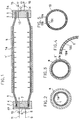
- Figs. 1 to 3 show the present method as practiced using a rigid plastic tube 1 having a relatively large wall thickness and formed with a multiplicity of bores 1a extending through the tube wall and having a circular cross section.
- the rigid tube 1 has a smaller diameter than the pipe a to be lined and a relatively large wall thickness.
- the rigid tube 1 which is smaller than the pipe a in diameter, is inserted through the pipe a over the entire length thereof, and the tube 1 is then closed at its opposite ends with a front closure 2 and a rear closure 3.
- the front closure 2 and the rear closure 3 have in their inner surfaces annular furrows 4 and 5, respectively, in which the respective ends of the tube 1 are fixedly fitted.
- These furrows 4, 5 have in their bottoms grooves 4a, 5a.
- the bores 1a extending through the wall of the tube 1 are opened at their opposite ends to the interior of the grooves 4a, 5a.
- the front closure 2 is formed with a channel 6 for supplying a heating fluid, such as steam, to the bores 1a via the groove 4a in the annular furrow 4, and has a channel 7 for supplying a pressure fluid, such as compressed air, to the interior of the tube 1.
- the inlet of the former channel 6 communicates with a boiler (not shown) through a conduit 9 having a valve 8.
- the inlet of the latter channel 7 is in communication with a compressor (not shown) via a conduit 11 having a valve 10.
- the rear closure 3 has a channel 12 for discharging steam from the bores 1a through the groove 5a, and a channel 13 for discharging compressed air from the tube 1.
- the outlets of the channels 12, 13 are respectively provided with conduits 16, 17 having valves 14, 15, respectively.
- steam is supplied to the bores 1a in the wall of the tube 1 through the steam supply system, i.e., through the conduit 9, the channel 6 and the groove 4a.
- the steam flows through the bores 1a while heating the tube 1 from inside its wall and is discharged to the outside through the discharge system, i.e., through the groove 5a, the channel 12 and the conduit 16.
- the tube 1 is heated with steam in this way usually at atmospheric pressure, the steam may be applied at a low pressure which will not inflate the wall around the bores 1a, for example, at a slightly elevated pressure of about 0.5 kp/cm2 (gauge pressure) when so desired.
- the tube 1 may be heated from inside utilizing the compressed air supply system.
- the wall can be heated substantially uniformly throughout its entire thickness although the wall is thick.
- compressed air which is preferably preheated to about 80 to about 100°C is fed to the interior of the tube 1 through the air supply system, i.e. through the conduit 11 and the channel 7, while continuously heating the tube from inside the bores 1a.
- the internal pressure of the tube 1 is raised to a level required for inflating the tube, for example, to about 0.5 to about 2.0 kp/cm2 (gauge pressure)
- the rigid tube 1 is inflated to line the pipe a .
- the lining thus formed is shown in Figs. 1 and 3. Since the tube 1 is heated to a uniform temperature throughout its wall thickness as already stated, the tube can be inflated into the lining uniformly over the entire length thereof free of the likelihood of rupture or the like although having a large wall thickness.
- the rigid tube lining 1' obtained by the method shown in Figs. 1 to 3 was checked for surface smoothness. As shown as exaggerated in the enlarged sectional view of Fig. 4, the lining was found to have slight surface irregularities including recesses 18a adjacent to the bores 1a and protuberances 18b adjacent to the solid wall portions between the bores.
- the surface smoothness of the rigid tube lining 1' can be improved by using a rigid plastic tube 19 having the structure shown in cross section in Fig. 5.
- the rigid tube 19 shown in Fig. 5 differs in structure from the rigid tube 1 of Figs. 1 to 3 in that the tube 19 has bores 19a having a triangular cross section and arranged in parallel as oriented in opposite directions alternately.
- the partitions 19b, 19b defining the oblique sides of the triangular bore 19a are approximately equal in thickness to the base wall 19c defining the base side of the bore 19a, such that the ratio between the void portion and the solid portion is approximately uniform at any diametrical section.
- any peripheral portion of the tube wall about the center of the tube similarly acts against the pressure, with the result that the tube is uniformly inflated in its entirety to give a smooth-surfaced lining.
- Example 1 The present method was practiced under the same experimental conditions as in Example 1 with the exception of using rigid plastic tubes of polyethylene or polypropylene. The results achieved were satisfactory and comparable to the result achieved in Example 1.
Landscapes
- Engineering & Computer Science (AREA)
- Mechanical Engineering (AREA)
- General Engineering & Computer Science (AREA)
- Manufacturing & Machinery (AREA)
- Physics & Mathematics (AREA)
- Thermal Sciences (AREA)
- Lining Or Joining Of Plastics Or The Like (AREA)
Claims (10)
- Verfahren zum Auskleiden einer Leitung mit einem starren oder halbstarren Kunststoffrohr, das in die Leitung eingeführt ist, durch Aufblasen des Rohrs unter Anwendung von Wärme und Druck, dadurch gekennzeichnet, daß das Rohr eine Wandstärke von etwa 5 mm bis etwa 20 mm hat und mit einer Vielzahl von Bohrungen versehen ist, die sich axial durch die Rohrwand erstrecken und parallel in einem Abstand entlang des Rohrumfangs angeordnet sind, wobei das Rohr durch Durchleiten eines Heizfluids durch die Bohrungen erwärmt wird.
- Auskleidungsverfahren nach Anspruch 1, worin das starre Kunststoffrohr einen Erweichungspunkt von etwa 60 bis etwa 100°C hat und das durch die Bohrungen geleitete Heizfluid Dampf ist.
- Auskleidungsverfahren nach Anspruch 1 oder 2, worin das starre Kunststoffrohr sowohl vom Inneren des Rohrs als auch vom Inneren der Bohrungen her erwärmt wird, indem das Heizfluid durch das Rohr und durch die Bohrungen geleitet wird.
- Auskleidungsverfahren nach Anspruch 3, worin das durch das Rohr geleitete Heizfluid Heißluft ist und das durch die Bohrungen geleitete Heizfluid Dampf ist.
- Auskleidungsverfahren nach irgendeinem vorangehenden Anspruch, worin die Bohrungen in einer kreisförmigen Anordnung konzentrisch mit dem Rohr angeordnet und im Zentrum der Rohrwanddicke positioniert sind.
- Verfahren nach irgendeinem vorangehenden Anspruch, worin die Gesamt-Querschnittsfläche der Bohrungen etwa 20 bis etwa 50% der Gesamtquerschnittsfläche des Kunststoffrohrs ausmacht.
- Verfahren nach Anspruch 6, worin die Öffnungsweite jeder Bohrung in radialer Richtung des Kunststoffrohrs im Bereich von etwa 40 bis etwa 70% der wandstärke ist und der Anstand zwischen den Bohrungen etwa 50 bis etwa 100% der Wandstärke entspricht.
- Verfahren nach irgendeinem vorangehenden Anspruch, worin die Bohrungen einen kreisförmigen Querschnitt haben.
- Verfahren nach irgendeinem der Ansprüche 1 bis 7, worin die Bohrungen einen dreieckigen Querschnitt haben, wobei alternierende Dreiecksquerschnitte in entgegengesetzter Richtung orientiert sind.
- Verfahren nach Anspruch 10, worin jede der Bohrungen mit dreieckigem Querschnitt durch drei Seitenwände mit im wesentlichen derselben Dicke definiert ist.
Applications Claiming Priority (4)
| Application Number | Priority Date | Filing Date | Title |
|---|---|---|---|
| JP90771/88 | 1988-04-12 | ||
| JP9077188 | 1988-04-12 | ||
| JP141178/88 | 1988-06-07 | ||
| JP14117888 | 1988-06-07 |
Publications (3)
| Publication Number | Publication Date |
|---|---|
| EP0337674A2 EP0337674A2 (de) | 1989-10-18 |
| EP0337674A3 EP0337674A3 (de) | 1991-05-02 |
| EP0337674B1 true EP0337674B1 (de) | 1993-06-09 |
Family
ID=26432203
Family Applications (1)
| Application Number | Title | Priority Date | Filing Date |
|---|---|---|---|
| EP89303455A Expired - Lifetime EP0337674B1 (de) | 1988-04-12 | 1989-04-07 | Verfahren zum Auskleiden einer Leitung mit einem starren Rohr |
Country Status (4)
| Country | Link |
|---|---|
| US (1) | US4965036A (de) |
| EP (1) | EP0337674B1 (de) |
| KR (1) | KR0133174B1 (de) |
| DE (1) | DE68906951T2 (de) |
Families Citing this family (9)
| Publication number | Priority date | Publication date | Assignee | Title |
|---|---|---|---|---|
| US5265981A (en) * | 1992-06-05 | 1993-11-30 | Mcneil Ronald A | System and method for rehabilitating a manhole, and manhole rehabilitated thereby |
| EP0584381B1 (de) * | 1992-08-20 | 1998-06-17 | Ivan C. Mandich | Verfahren zum Installieren eines Plastikliners in einem Rohr |
| EP0585855B1 (de) * | 1992-08-29 | 1997-01-02 | Tokai Rubber Industries, Ltd. | Verfahren zur Herstellung eines laminierten Schlauches |
| US5490744A (en) * | 1993-12-08 | 1996-02-13 | Mcneil; Ronald A. | Method and apparatus for inflating and curing a resin impregnated manhole liner |
| US6220079B1 (en) | 1998-07-22 | 2001-04-24 | Safety Liner Systems, L.L.C. | Annular fluid manipulation in lined tubular systems |
| US6634388B1 (en) | 1998-07-22 | 2003-10-21 | Safetyliner Systems, Llc | Annular fluid manipulation in lined tubular systems |
| CA2338676C (en) | 1998-07-29 | 2008-09-16 | United Pipeline Systems, Inc. | Insertion of liners into host tubulars by fluid injection |
| EP1345754A4 (de) * | 2000-06-09 | 2006-04-19 | Fiberliner Networks | Verfahren und vorrichtung zur auskleidung einer leitung |
| CA3096558C (en) * | 2018-05-23 | 2023-10-10 | Nu Flow Technologies 2000 Inc. | Liner assembly for pipelines and related method |
Citations (2)
| Publication number | Priority date | Publication date | Assignee | Title |
|---|---|---|---|---|
| JPS577052B2 (de) * | 1976-01-19 | 1982-02-08 | ||
| JPS6218333B2 (de) * | 1978-03-15 | 1987-04-22 | Sekisui Chemical Co Ltd |
Family Cites Families (13)
| Publication number | Priority date | Publication date | Assignee | Title |
|---|---|---|---|---|
| US79220A (en) * | 1868-06-23 | Improvement in lining flexible and other hose and tubes with india-rubber | ||
| US3996967A (en) * | 1972-10-18 | 1976-12-14 | Takata Kojyo Co., Ltd. | Reinforced lining for tubes |
| FR2343957A1 (fr) * | 1976-03-08 | 1977-10-07 | Wavin Bv | Tube en materiau synthetique dont la paroi est pourvue de canaux longitudinaux |
| JPS5922653B2 (ja) * | 1976-12-17 | 1984-05-28 | 積水化学工業株式会社 | 管体の内面裏打ち方法 |
| JPS54148071A (en) * | 1978-05-13 | 1979-11-19 | Hakko Kasei Kogyosho:Kk | Method of lining of bended metal pipe with synthetic resin tube |
| JPS5655223A (en) * | 1979-10-12 | 1981-05-15 | Kubota Ltd | Method of molding spigot of porous plastic tube |
| JPS5783421A (en) * | 1980-11-12 | 1982-05-25 | Kubota Ltd | Forming method of faucet of perforated plastics tube |
| US4585371A (en) * | 1981-03-14 | 1986-04-29 | Dunlop Limited | Lining of tubular structures |
| JPS57154581A (en) * | 1981-03-18 | 1982-09-24 | Meiken Setsukei Kk | Coating method of inner face of buried pipe |
| JPS5824679A (ja) * | 1981-08-05 | 1983-02-14 | 住友電気工業株式会社 | 埋設管内面被覆工法 |
| JPS5888281A (ja) * | 1981-11-17 | 1983-05-26 | 住友電気工業株式会社 | 埋設管内面被覆工法 |
| GB2188695A (en) * | 1986-03-31 | 1987-10-07 | Jr Campbell Hall Steketee | Lining pipes |
| JPH01205117A (ja) * | 1988-02-10 | 1989-08-17 | Ricoh Co Ltd | リアコンバーターレンズ |
-
1989
- 1989-04-04 US US07/332,905 patent/US4965036A/en not_active Expired - Lifetime
- 1989-04-07 DE DE89303455T patent/DE68906951T2/de not_active Expired - Fee Related
- 1989-04-07 EP EP89303455A patent/EP0337674B1/de not_active Expired - Lifetime
- 1989-04-11 KR KR1019890004771A patent/KR0133174B1/ko not_active Expired - Fee Related
Patent Citations (2)
| Publication number | Priority date | Publication date | Assignee | Title |
|---|---|---|---|---|
| JPS577052B2 (de) * | 1976-01-19 | 1982-02-08 | ||
| JPS6218333B2 (de) * | 1978-03-15 | 1987-04-22 | Sekisui Chemical Co Ltd |
Also Published As
| Publication number | Publication date |
|---|---|
| DE68906951T2 (de) | 1994-01-13 |
| US4965036A (en) | 1990-10-23 |
| EP0337674A3 (de) | 1991-05-02 |
| KR890016324A (ko) | 1989-11-28 |
| DE68906951D1 (de) | 1993-07-15 |
| KR0133174B1 (ko) | 1998-04-13 |
| EP0337674A2 (de) | 1989-10-18 |
Similar Documents
| Publication | Publication Date | Title |
|---|---|---|
| EP0337674B1 (de) | Verfahren zum Auskleiden einer Leitung mit einem starren Rohr | |
| US2608501A (en) | Method of and apparatus for making lined pipe | |
| US5827467A (en) | Method and apparatus for forming flanges on tubes | |
| GB1589052A (en) | Pipe of oriented thermoplastic polymeric material and method of forming the same | |
| AU2002348127B2 (en) | Internally cooled punch | |
| JP2007125894A (ja) | ブロー成形用金型装置 | |
| US4598857A (en) | Method of producing double-wall composite pipes | |
| US4150087A (en) | Tube of thermoplastics with thickened end | |
| JP6614606B1 (ja) | タイヤ加硫機の配管構造及びタイヤ加硫機によるタイヤ加硫方法 | |
| JPS6344525B2 (de) | ||
| EP0339533B1 (de) | Vorrichtung zum Herstellen von warmschrumpfbaren Kunststoffrohren | |
| JP2003340824A (ja) | タイヤの加硫成型方法およびタイヤ成形用金型 | |
| JPS5930495A (ja) | 配管内部の局部冷却装置 | |
| US5693175A (en) | Clamp for making tubing | |
| JP4436669B2 (ja) | タイヤ用のインナーライナーを深さ方向に部分的に加硫する方法および装置 | |
| US1910128A (en) | Apparatus for treating rubber tires | |
| EP0176524B1 (de) | Formverfahren | |
| GB2080190A (en) | A method of and an apparatus for moulding and vulcanizing driving belts | |
| JPH0278528A (ja) | 管内面の硬質チューブライニング工法 | |
| EP0456056B1 (de) | Kupplungsbestandteil und Verfahren zu dessen Herstellung | |
| SI9110845A (en) | Improved method of manufacture of lamellar tubular body | |
| CN210630737U (zh) | 压鞋机 | |
| US1271843A (en) | Method of manufacturing rubber footwear. | |
| JP4754132B2 (ja) | 伝動ベルト等の成形型及びこれを用いた加硫装置 | |
| US5863569A (en) | Apparatus for forming bellings on thermoplastic pipes |
Legal Events
| Date | Code | Title | Description |
|---|---|---|---|
| PUAI | Public reference made under article 153(3) epc to a published international application that has entered the european phase |
Free format text: ORIGINAL CODE: 0009012 |
|
| AK | Designated contracting states |
Kind code of ref document: A2 Designated state(s): DE FR GB |
|
| PUAL | Search report despatched |
Free format text: ORIGINAL CODE: 0009013 |
|
| AK | Designated contracting states |
Kind code of ref document: A3 Designated state(s): DE FR GB |
|
| 17P | Request for examination filed |
Effective date: 19910608 |
|
| 17Q | First examination report despatched |
Effective date: 19911106 |
|
| GRAA | (expected) grant |
Free format text: ORIGINAL CODE: 0009210 |
|
| AK | Designated contracting states |
Kind code of ref document: B1 Designated state(s): DE FR GB |
|
| REF | Corresponds to: |
Ref document number: 68906951 Country of ref document: DE Date of ref document: 19930715 |
|
| ET | Fr: translation filed | ||
| PLBE | No opposition filed within time limit |
Free format text: ORIGINAL CODE: 0009261 |
|
| STAA | Information on the status of an ep patent application or granted ep patent |
Free format text: STATUS: NO OPPOSITION FILED WITHIN TIME LIMIT |
|
| 26N | No opposition filed | ||
| PGFP | Annual fee paid to national office [announced via postgrant information from national office to epo] |
Ref country code: FR Payment date: 19960328 Year of fee payment: 8 |
|
| PGFP | Annual fee paid to national office [announced via postgrant information from national office to epo] |
Ref country code: GB Payment date: 19960402 Year of fee payment: 8 |
|
| PGFP | Annual fee paid to national office [announced via postgrant information from national office to epo] |
Ref country code: DE Payment date: 19960426 Year of fee payment: 8 |
|
| PG25 | Lapsed in a contracting state [announced via postgrant information from national office to epo] |
Ref country code: GB Effective date: 19970407 |
|
| GBPC | Gb: european patent ceased through non-payment of renewal fee |
Effective date: 19970407 |
|
| PG25 | Lapsed in a contracting state [announced via postgrant information from national office to epo] |
Ref country code: FR Free format text: LAPSE BECAUSE OF NON-PAYMENT OF DUE FEES Effective date: 19971231 |
|
| PG25 | Lapsed in a contracting state [announced via postgrant information from national office to epo] |
Ref country code: DE Free format text: LAPSE BECAUSE OF NON-PAYMENT OF DUE FEES Effective date: 19980101 |
|
| REG | Reference to a national code |
Ref country code: FR Ref legal event code: ST |