EP0337155A2 - Réseau de bord pour un véhicule - Google Patents
Réseau de bord pour un véhicule Download PDFInfo
- Publication number
- EP0337155A2 EP0337155A2 EP19890104852 EP89104852A EP0337155A2 EP 0337155 A2 EP0337155 A2 EP 0337155A2 EP 19890104852 EP19890104852 EP 19890104852 EP 89104852 A EP89104852 A EP 89104852A EP 0337155 A2 EP0337155 A2 EP 0337155A2
- Authority
- EP
- European Patent Office
- Prior art keywords
- battery
- electrical system
- voltage
- motor vehicle
- vehicle according
- Prior art date
- Legal status (The legal status is an assumption and is not a legal conclusion. Google has not performed a legal analysis and makes no representation as to the accuracy of the status listed.)
- Granted
Links
Images

Classifications
-
- F—MECHANICAL ENGINEERING; LIGHTING; HEATING; WEAPONS; BLASTING
- F02—COMBUSTION ENGINES; HOT-GAS OR COMBUSTION-PRODUCT ENGINE PLANTS
- F02N—STARTING OF COMBUSTION ENGINES; STARTING AIDS FOR SUCH ENGINES, NOT OTHERWISE PROVIDED FOR
- F02N11/00—Starting of engines by means of electric motors
- F02N11/08—Circuits or control means specially adapted for starting of engines
- F02N11/0862—Circuits or control means specially adapted for starting of engines characterised by the electrical power supply means, e.g. battery
- F02N11/0866—Circuits or control means specially adapted for starting of engines characterised by the electrical power supply means, e.g. battery comprising several power sources, e.g. battery and capacitor or two batteries
-
- H—ELECTRICITY
- H02—GENERATION; CONVERSION OR DISTRIBUTION OF ELECTRIC POWER
- H02J—CIRCUIT ARRANGEMENTS OR SYSTEMS FOR SUPPLYING OR DISTRIBUTING ELECTRIC POWER; SYSTEMS FOR STORING ELECTRIC ENERGY
- H02J7/00—Circuit arrangements for charging or depolarising batteries or for supplying loads from batteries
- H02J7/14—Circuit arrangements for charging or depolarising batteries or for supplying loads from batteries for charging batteries from dynamo-electric generators driven at varying speed, e.g. on vehicle
- H02J7/1423—Circuit arrangements for charging or depolarising batteries or for supplying loads from batteries for charging batteries from dynamo-electric generators driven at varying speed, e.g. on vehicle with multiple batteries
-
- B—PERFORMING OPERATIONS; TRANSPORTING
- B60—VEHICLES IN GENERAL
- B60R—VEHICLES, VEHICLE FITTINGS, OR VEHICLE PARTS, NOT OTHERWISE PROVIDED FOR
- B60R16/00—Electric or fluid circuits specially adapted for vehicles and not otherwise provided for; Arrangement of elements of electric or fluid circuits specially adapted for vehicles and not otherwise provided for
- B60R16/02—Electric or fluid circuits specially adapted for vehicles and not otherwise provided for; Arrangement of elements of electric or fluid circuits specially adapted for vehicles and not otherwise provided for electric constitutive elements
- B60R16/03—Electric or fluid circuits specially adapted for vehicles and not otherwise provided for; Arrangement of elements of electric or fluid circuits specially adapted for vehicles and not otherwise provided for electric constitutive elements for supply of electrical power to vehicle subsystems or for
-
- H—ELECTRICITY
- H02—GENERATION; CONVERSION OR DISTRIBUTION OF ELECTRIC POWER
- H02J—CIRCUIT ARRANGEMENTS OR SYSTEMS FOR SUPPLYING OR DISTRIBUTING ELECTRIC POWER; SYSTEMS FOR STORING ELECTRIC ENERGY
- H02J2310/00—The network for supplying or distributing electric power characterised by its spatial reach or by the load
- H02J2310/40—The network being an on-board power network, i.e. within a vehicle
- H02J2310/46—The network being an on-board power network, i.e. within a vehicle for ICE-powered road vehicles
-
- H—ELECTRICITY
- H02—GENERATION; CONVERSION OR DISTRIBUTION OF ELECTRIC POWER
- H02J—CIRCUIT ARRANGEMENTS OR SYSTEMS FOR SUPPLYING OR DISTRIBUTING ELECTRIC POWER; SYSTEMS FOR STORING ELECTRIC ENERGY
- H02J7/00—Circuit arrangements for charging or depolarising batteries or for supplying loads from batteries
- H02J7/14—Circuit arrangements for charging or depolarising batteries or for supplying loads from batteries for charging batteries from dynamo-electric generators driven at varying speed, e.g. on vehicle
- H02J7/143—Circuit arrangements for charging or depolarising batteries or for supplying loads from batteries for charging batteries from dynamo-electric generators driven at varying speed, e.g. on vehicle with multiple generators
-
- Y—GENERAL TAGGING OF NEW TECHNOLOGICAL DEVELOPMENTS; GENERAL TAGGING OF CROSS-SECTIONAL TECHNOLOGIES SPANNING OVER SEVERAL SECTIONS OF THE IPC; TECHNICAL SUBJECTS COVERED BY FORMER USPC CROSS-REFERENCE ART COLLECTIONS [XRACs] AND DIGESTS
- Y02—TECHNOLOGIES OR APPLICATIONS FOR MITIGATION OR ADAPTATION AGAINST CLIMATE CHANGE
- Y02T—CLIMATE CHANGE MITIGATION TECHNOLOGIES RELATED TO TRANSPORTATION
- Y02T10/00—Road transport of goods or passengers
- Y02T10/60—Other road transportation technologies with climate change mitigation effect
- Y02T10/70—Energy storage systems for electromobility, e.g. batteries
Definitions
- the invention is based on an electrical system for a motor vehicle according to the preamble of the main claim.
- Electrical energy for a motor vehicle electrical system is usually generated using a three-phase generator, the output voltage of which is regulated by a voltage regulator to the value required for the voltage supply to the electrical system.
- a battery serves as an energy store, but often does not meet the requirements placed on it.
- Motor vehicle electrical system systems have therefore been proposed which have two batteries connected in series, which in turn are supplied with electrical energy by one or two generators.
- DE-OS 33 09 856 a DC electrical system for a vehicle is known, in which an AC generator with two magnetically separated field windings and associated armature windings via two rectifier systems, two storage batteries, which are connected in series, supplied with electrical energy.
- the voltage is regulated by means of two voltage regulators so that the voltage applied to the two batteries is the same value, in each case 12 volts in the exemplary embodiment of DE-OS 33 09 856. Since the two batteries are connected in series, the sum of the two battery voltages can be tapped between one terminal of the first battery and the other terminal of the second battery, ie 24 volts in the exemplary embodiment mentioned.
- the vehicle electrical system according to the invention for a motor vehicle with the characterizing features of the main claim has the advantage that, by using two generators or batteries with different nominal voltages, the consumers can be connected to the battery with the more suitable nominal voltage according to their voltage requirements. Through the series connection of the two batteries with different nominal voltages, a third voltage can also be tapped directly as the sum of the two different individual voltages.
- voltage-sensitive components for example for ignition and / or injection on one battery and the starter on the other battery, can be connected with the higher voltage, so that the voltage drop at the start does not disturb the voltage-sensitive components.
- FIG. 2 shows a second exemplary embodiment of the invention, which shows some details of the electrical system.
- the reference symbols used in FIG. 1 are used again in FIG. 2 for corresponding elements.
- FIG. 1 An electrical system for a motor vehicle is shown schematically in FIG.
- Two batteries 10 and 11 are connected in series with one another, the negative terminal of the battery 10 and the positive terminal of the battery 11 being connected to one another.
- the positive pole of the battery 10 is connected to a voltage tap or voltage terminal 12, the negative pole of the battery 10 or the positive pole of the battery 11 to a voltage tap 13 or to ground and the positive pole of the battery 11 to a voltage tap 14.
- a first generator 15 Between terminal 12 and Ground are a first generator 15, a first motor 17, for example the fuel pump, a first lamp 19, a consumer 21, which, for example, is used for ignition and / or injection represents essential components and switched a DC-DC converter 22.
- Electronic components 23 are connected between the voltage converter 22 and ground.
- a second generator 16, a second motor 18, for example the windshield wiper motor and further consumers 20, are connected between the voltage terminal 14 and ground.
- a further consumer 24 and optionally an additional motor 25, for example the fan, are connected to the terminals 12 and 14.
- the starter 26 is supplied with voltage by the battery 11 via the voltage connections 13 and 14.
- the battery 10 or the generator 15 has a nominal voltage of 12 volts
- the battery 11 or the generator 16 have a nominal voltage of 24 volts.
- the starter 26, the motor 18 and a consumer 20 are operated with a voltage of 24 volts, the motor 18 being a power consumer, for example a motor for the water pump or the oil pump, and the consumers 20 are voltage-insensitive consumers with high power consumption, for example seat heaters, heated rear window, etc.
- the motor 18 being a power consumer, for example a motor for the water pump or the oil pump
- the consumers 20 are voltage-insensitive consumers with high power consumption, for example seat heaters, heated rear window, etc.
- the battery 10 in embodiment 1 is a battery with a nominal voltage of 12 volts, it supplies the voltage-sensitive components such as incandescent lamps, small consumers, voltage converters and, via the voltage converters, also electronic components with the required constant voltage. Since the starter is not supplied with power by the battery 10, no problems relating to a voltage drop occur for the consumers connected to the battery 10 in the event of a start. Therefore, the components essential for ignition and injection are connected to the battery 10 (12 volt nominal voltage). In FIG. 1, these components are represented by the consumer 21.
- the consumers that are supplied with 12 volts or 24 volts can be grounded on one side.
- the 36 volt loads 24 and 25 shown in FIG. 1, on the other hand, must be insulated from ground on both poles.
- the batteries 10 and 11 can be selected or dimensioned according to their task, the 12 volt battery 10 should only supply the vehicle electrical system, i.e. there is no design for high currents in the cold.
- the 24 volt battery on the other hand, can be designed in such a way that optimum cold start and on-board power supply are guaranteed. In contrast to battery 10, it should therefore be designed for a high current load.
- connection 12 would be at minus 12 volts
- connection 13 would still be at ground
- connection 14 at plus 24 volts.
- any other combinations are possible, for example 12 volts and 36 volts, so that a voltage of 48 volts is also tapped as the voltage sum of the series connection of the two batteries can be.
- Three generators and three batteries can also be used.
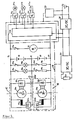
- FIG 2 shows a second embodiment of an electrical system for a motor vehicle, which shows some details that were not explicitly shown in the embodiment of Figure 1.
- Two batteries 10 and 11 with the terminals 12, 13 and 14 are connected in series.
- a first generator 15, which supplies the battery 10 with voltage is connected between the terminals 12 and 13, between the terminals 13 and 14, a second generator 16, which supplies the battery 11 with voltage.
- To the first battery 10 two light bulbs 19a and 19b are connected to the terminals 12 and 13 via switches 27a and 27b.
- consumers 20a and 20b are connected to the terminals 13 and 14 via switches 27c and 27d.
- the terminal 13 is still connected to ground.
- the starter 26 is connected to the terminal 12 of the battery 10 and the terminal 14 of the battery 11 via a further switch 27e.
- a voltage ring network 28 for example a multiplex ring network, is connected to the same terminals 12 and 14 and supplies consumers 21a, b, c with voltage via components 23a, b, c. These components 23 are controlled with the aid of an electronic circuit 37, which is connected to the components 23a, b, c via a data ring line 29.
- the electronic circuit 37 also controls a DC / DC converter 38 and a DC / AC converter 39, both of which are supplied with voltage via the ring network 28.
- a heating disk 40 is connected to the DC / AC converter and operates with an 80 volt, 1 kHz alternating voltage becomes.
- the DC / DC converter supplies a 5 volt DC voltage which is present on a battery 32 and which supplies the electronic circuit 37 with voltage.
- the power supply to the consumers can also be accomplished by means of a radiation or mesh network.
- the starter 26 is due to the total voltage that is present between the terminals 12 and 14.
- the individual components of the circuit are connected to one another via the data ring line 29 and are controlled by means of the electronic circuit 37.
- the generators 15 and 16 of both exemplary embodiments are alternating current generators, one of which is designed, for example, as a permanently excited generator and is therefore suitable as a “base load generator”, and each contain field windings 33a, b and armature windings 34a, b.
- the output voltage is kept at the desired value by means of two regulators 35a, 35b.
- the output voltage is rectified in rectifier systems 36a, b before it is fed into the vehicle electrical system.
- the two generators can be driven by a multi-ribbed belt, thus reducing the torque required per generator and distributing the belt forces to different belt sections.
- a higher nominal voltage for example 36 volts, which supplies both batteries, for example a 12 volt battery and a 24 volt battery, with an electronic circuit (balancing circuit), can be used to generate the voltage.
Applications Claiming Priority (2)
| Application Number | Priority Date | Filing Date | Title |
|---|---|---|---|
| DE3812577A DE3812577A1 (de) | 1988-04-15 | 1988-04-15 | Bordnetz fuer ein kraftfahrzeug |
| DE3812577 | 1988-04-15 |
Publications (3)
| Publication Number | Publication Date |
|---|---|
| EP0337155A2 true EP0337155A2 (fr) | 1989-10-18 |
| EP0337155A3 EP0337155A3 (en) | 1990-01-17 |
| EP0337155B1 EP0337155B1 (fr) | 1992-12-23 |
Family
ID=6352075
Family Applications (1)
| Application Number | Title | Priority Date | Filing Date |
|---|---|---|---|
| EP89104852A Expired - Lifetime EP0337155B1 (fr) | 1988-04-15 | 1989-03-17 | Réseau de bord pour un véhicule |
Country Status (3)
| Country | Link |
|---|---|
| EP (1) | EP0337155B1 (fr) |
| JP (1) | JPH01308133A (fr) |
| DE (2) | DE3812577A1 (fr) |
Cited By (4)
| Publication number | Priority date | Publication date | Assignee | Title |
|---|---|---|---|---|
| EP0464694A2 (fr) * | 1990-06-28 | 1992-01-08 | Nippondenso Co., Ltd. | Alimentation de puissance pour véhicule automobile |
| EP0569278A1 (fr) * | 1992-05-07 | 1993-11-10 | Valeo Equipements Electriques Moteur | Dispositif d'alimentation électrique sous tension élevée d'un circuit auxiliaire de véhicule automobile |
| WO2000076812A1 (fr) * | 1999-06-09 | 2000-12-21 | Lear Automotive (Eeds) Spain, S.L. | Boite de distribution electrique pour vehicules dotes de deux reseaux a niveaux de tension differents |
| WO2001032473A1 (fr) * | 1999-11-05 | 2001-05-10 | Volkswagen Aktiengesellschaft | Reseau de bord de vehicule |
Families Citing this family (22)
| Publication number | Priority date | Publication date | Assignee | Title |
|---|---|---|---|---|
| DE4041220A1 (de) * | 1990-12-21 | 1992-07-02 | Vogt Electronic Ag | Stromversorgung fuer kraftfahrzeuge |
| DE4108861C2 (de) * | 1991-03-19 | 2002-06-27 | Bosch Gmbh Robert | Einrichtung zur Spannungsversorgung in einem Kraftfahrzeug mit parallel geschalteten Generatoren |
| JP3099405B2 (ja) * | 1991-04-24 | 2000-10-16 | 株式会社デンソー | 車両用電源装置 |
| US6218643B1 (en) * | 1991-07-18 | 2001-04-17 | Mitsubishi Denki Kabushiki Kaisha | Power supplying apparatus for automotive part |
| DE4138943C1 (fr) * | 1991-11-27 | 1993-05-27 | Robert Bosch Gmbh, 7000 Stuttgart, De | |
| JP3039119B2 (ja) * | 1992-03-31 | 2000-05-08 | 日産自動車株式会社 | 車両用電源装置 |
| DE4300535A1 (de) * | 1993-01-12 | 1994-07-14 | Wuerth Elektronik Gmbh & Co Kg | Vorrichtung zur Verbindung eines elektrischen Verbrauchers mit einer Spannungsquelle |
| DE19609009A1 (de) * | 1996-03-08 | 1997-09-11 | Edag Eng & Design Ag | Elektrisches Netz mit mehreren elektrischen Verbrauchern |
| DE19720816A1 (de) * | 1997-05-16 | 1998-11-19 | Wegmann & Co Gmbh | Elektrische Versorgungseinrichtung für ein militärisches Fahrzeug, insbesondere für einen mit einem Turm versehenen Panzer |
| DE19752661C2 (de) † | 1997-11-27 | 2001-09-13 | Siemens Ag | Bordnetz für ein Kraftfahrzeug |
| DE19907852A1 (de) * | 1999-02-24 | 2000-08-31 | Bayerische Motoren Werke Ag | Generatorsystem |
| DE19930017A1 (de) * | 1999-06-30 | 2001-01-04 | Volkswagen Ag | Vorrichtung zur Spannungserzeugung in einem Kraftfahrzeug |
| DE10042524A1 (de) * | 2000-08-30 | 2002-03-28 | Audi Ag | Spannungsversorgungseinrichtung für ein Kraftfahrzeug |
| DE10106723B4 (de) * | 2001-02-14 | 2005-01-27 | Robert Bosch Gmbh | Vorrichtung zur Energieversorgung mehrerer Spannungsbordnetze und Batterien |
| DE10131435A1 (de) * | 2001-06-29 | 2002-06-27 | Daimler Chrysler Ag | Personenkraftwagen mit zwei Bordnetzen unterschiedlicher Spannung |
| JP2003235176A (ja) * | 2002-02-07 | 2003-08-22 | Sumitomo Electric Ind Ltd | 電池の充電システム |
| DE10304764B3 (de) | 2003-02-05 | 2004-02-26 | Daimlerchrysler Ag | Zwei-Spannungs-Bordnetz |
| DE10338160A1 (de) * | 2003-08-20 | 2005-03-24 | Audi Ag | Spannungsversorgungseinrichtung für ein Kraftfahrzeug |
| DE102004008433A1 (de) | 2004-02-19 | 2005-09-08 | Robert Bosch Gmbh | Vorrichtung zur Spannungsversorgung |
| US9240685B2 (en) * | 2013-01-21 | 2016-01-19 | Hamilton Sundstrand Corporation | Reconfigurable matrix-based power distribution architecture |
| DE102015208542A1 (de) * | 2015-05-07 | 2016-09-08 | Continental Automotive Gmbh | Versorgungseinrichtung für ein Bordnetz und Bordnetz mit Versorgungseinrichtung |
| US11001213B2 (en) | 2019-07-17 | 2021-05-11 | Ford Global Technologies, Llc | Onboard AC generator for power-to-the-box in vehicles with combustion engine |
Citations (5)
| Publication number | Priority date | Publication date | Assignee | Title |
|---|---|---|---|---|
| US4045718A (en) * | 1975-04-02 | 1977-08-30 | Maremont Corporation | Multiple winding multiple voltage alternator electrical supply system |
| GB1585915A (en) * | 1977-07-26 | 1981-03-11 | Scheidler R | Dual battery charge control |
| DE3007941A1 (de) * | 1980-03-01 | 1981-09-17 | Robert Bosch Gmbh, 7000 Stuttgart | Zweispannungs-netzanlage |
| US4604565A (en) * | 1982-05-20 | 1986-08-05 | Mitsubishi Denki Kabushiki Kaisha | Microcomputer-controlled DC three-wire circuit for vehicle |
| EP0232828A2 (fr) * | 1986-02-14 | 1987-08-19 | Hitachi, Ltd. | Système d'alimentation pour véhicule ayant plusieurs tensions d'alimentation de puissance |
-
1988
- 1988-04-15 DE DE3812577A patent/DE3812577A1/de not_active Withdrawn
-
1989
- 1989-03-17 EP EP89104852A patent/EP0337155B1/fr not_active Expired - Lifetime
- 1989-03-17 DE DE8989104852T patent/DE58903070D1/de not_active Expired - Fee Related
- 1989-04-14 JP JP1093283A patent/JPH01308133A/ja active Pending
Patent Citations (5)
| Publication number | Priority date | Publication date | Assignee | Title |
|---|---|---|---|---|
| US4045718A (en) * | 1975-04-02 | 1977-08-30 | Maremont Corporation | Multiple winding multiple voltage alternator electrical supply system |
| GB1585915A (en) * | 1977-07-26 | 1981-03-11 | Scheidler R | Dual battery charge control |
| DE3007941A1 (de) * | 1980-03-01 | 1981-09-17 | Robert Bosch Gmbh, 7000 Stuttgart | Zweispannungs-netzanlage |
| US4604565A (en) * | 1982-05-20 | 1986-08-05 | Mitsubishi Denki Kabushiki Kaisha | Microcomputer-controlled DC three-wire circuit for vehicle |
| EP0232828A2 (fr) * | 1986-02-14 | 1987-08-19 | Hitachi, Ltd. | Système d'alimentation pour véhicule ayant plusieurs tensions d'alimentation de puissance |
Cited By (7)
| Publication number | Priority date | Publication date | Assignee | Title |
|---|---|---|---|---|
| EP0464694A2 (fr) * | 1990-06-28 | 1992-01-08 | Nippondenso Co., Ltd. | Alimentation de puissance pour véhicule automobile |
| EP0464694A3 (en) * | 1990-06-28 | 1993-03-31 | Nippondenso Co., Ltd. | Power source unit for an automotive vehicle |
| EP0569278A1 (fr) * | 1992-05-07 | 1993-11-10 | Valeo Equipements Electriques Moteur | Dispositif d'alimentation électrique sous tension élevée d'un circuit auxiliaire de véhicule automobile |
| FR2690889A1 (fr) * | 1992-05-07 | 1993-11-12 | Valeo Equip Electr Moteur | Dispositif d'alimentation électrique sous tension élevée d'un circuit auxiliaire de véhicule automobile. |
| WO2000076812A1 (fr) * | 1999-06-09 | 2000-12-21 | Lear Automotive (Eeds) Spain, S.L. | Boite de distribution electrique pour vehicules dotes de deux reseaux a niveaux de tension differents |
| US6879057B1 (en) | 1999-06-09 | 2005-04-12 | Lear Automotive (Eeds) Spain, S.L. | Electrical distribution box for vehicles having two networks with different voltage levels |
| WO2001032473A1 (fr) * | 1999-11-05 | 2001-05-10 | Volkswagen Aktiengesellschaft | Reseau de bord de vehicule |
Also Published As
| Publication number | Publication date |
|---|---|
| EP0337155B1 (fr) | 1992-12-23 |
| EP0337155A3 (en) | 1990-01-17 |
| DE58903070D1 (de) | 1993-02-04 |
| DE3812577A1 (de) | 1989-10-26 |
| JPH01308133A (ja) | 1989-12-12 |
Similar Documents
| Publication | Publication Date | Title |
|---|---|---|
| EP0337155B1 (fr) | Réseau de bord pour un véhicule | |
| DE3743317C2 (fr) | ||
| DE102018108383A1 (de) | In ein elektrisches fahrzeugsystem integrierter solarkollektor-power-point-tracker | |
| DE2650851A1 (de) | Stromversorgungseinrichtung fuer eine zweispannungsanlage in einem kraftfahrzeug | |
| DE10148248A1 (de) | Verfahren und elektrisches System zum energiereichen Anlassen eines Motors eines Kraftfahrzeuges | |
| US4100474A (en) | Multi-voltage vehicular network system | |
| DE102012203612A1 (de) | Batterieladegerät mit Spannungswandler und Verfahren zum Laden von Batterien | |
| DE3719376A1 (de) | Stromerzeuger | |
| DE3801478C2 (de) | Stromversorgungsschaltung für ein Kraftfahrzeug mit zwei unterschiedlichen Verbraucherspannungen | |
| DE69630231T2 (de) | Versorgungseinheit für ein elektrisches Fahrzeug | |
| DE3007941C2 (fr) | ||
| DE10148247A1 (de) | Verfahren zum Aufladen eines Energiespeichers und System zur Leistungsabgabe mit Impulsaufladung für ein Fahrzeug | |
| DE4226311A1 (de) | Drehstromgenerator | |
| EP0386055B1 (fr) | Circuits de bord de vehicules | |
| DE4437876A1 (de) | Verfahren zum Betreiben der elektrischen Stromversorgung in einem Elektrofahrzeug | |
| DE10232416B4 (de) | Schaltungsanordnung und Verfahren zum Stabilisieren einer Versorgungsspannung | |
| DE19953373B4 (de) | Vorrichtung zur Spannungsversorgung in einem Kraftfahrzeug | |
| EP1145913A2 (fr) | Réseau de bord d'une automobile avèc stabilisateur de tension | |
| DE3142878A1 (de) | Bordnetzgenerator fuer fahrzeuge | |
| DE10106723B4 (de) | Vorrichtung zur Energieversorgung mehrerer Spannungsbordnetze und Batterien | |
| DE2735114A1 (de) | Steuervorrichtung zum laden von in reihe geschalteten elektrischen batterien | |
| EP0760312B1 (fr) | Circuit pour l'alimentation des consommateurs | |
| EP3316432A1 (fr) | Dispositif d'alimentation électrique pourvu d'une interface permettant de faire fonctionner un système multitention | |
| EP1834842B1 (fr) | Dispositif d'alimentation électrique d'un véhicule utilitaire | |
| DE605925C (de) | Einrichtung zur Konstanthaltung der Hilfsnetzspannung auf dieselelektrischen Fahrzeugen |
Legal Events
| Date | Code | Title | Description |
|---|---|---|---|
| PUAI | Public reference made under article 153(3) epc to a published international application that has entered the european phase |
Free format text: ORIGINAL CODE: 0009012 |
|
| AK | Designated contracting states |
Kind code of ref document: A2 Designated state(s): DE FR GB IT |
|
| PUAL | Search report despatched |
Free format text: ORIGINAL CODE: 0009013 |
|
| AK | Designated contracting states |
Kind code of ref document: A3 Designated state(s): DE FR GB IT |
|
| 17P | Request for examination filed |
Effective date: 19900629 |
|
| 17Q | First examination report despatched |
Effective date: 19910424 |
|
| RAP3 | Party data changed (applicant data changed or rights of an application transferred) |
Owner name: ROBERT BOSCH GMBH |
|
| GRAA | (expected) grant |
Free format text: ORIGINAL CODE: 0009210 |
|
| AK | Designated contracting states |
Kind code of ref document: B1 Designated state(s): DE FR GB IT |
|
| ET | Fr: translation filed | ||
| GBT | Gb: translation of ep patent filed (gb section 77(6)(a)/1977) |
Effective date: 19921222 |
|
| REF | Corresponds to: |
Ref document number: 58903070 Country of ref document: DE Date of ref document: 19930204 |
|
| ITF | It: translation for a ep patent filed |
Owner name: STUDIO JAUMANN |
|
| PLBE | No opposition filed within time limit |
Free format text: ORIGINAL CODE: 0009261 |
|
| STAA | Information on the status of an ep patent application or granted ep patent |
Free format text: STATUS: NO OPPOSITION FILED WITHIN TIME LIMIT |
|
| 26N | No opposition filed | ||
| PGFP | Annual fee paid to national office [announced via postgrant information from national office to epo] |
Ref country code: GB Payment date: 19990302 Year of fee payment: 11 |
|
| PGFP | Annual fee paid to national office [announced via postgrant information from national office to epo] |
Ref country code: FR Payment date: 19990323 Year of fee payment: 11 |
|
| PG25 | Lapsed in a contracting state [announced via postgrant information from national office to epo] |
Ref country code: GB Free format text: LAPSE BECAUSE OF NON-PAYMENT OF DUE FEES Effective date: 20000317 |
|
| GBPC | Gb: european patent ceased through non-payment of renewal fee |
Effective date: 20000317 |
|
| PG25 | Lapsed in a contracting state [announced via postgrant information from national office to epo] |
Ref country code: FR Free format text: LAPSE BECAUSE OF NON-PAYMENT OF DUE FEES Effective date: 20001130 |
|
| REG | Reference to a national code |
Ref country code: FR Ref legal event code: ST |
|
| PG25 | Lapsed in a contracting state [announced via postgrant information from national office to epo] |
Ref country code: IT Free format text: LAPSE BECAUSE OF NON-PAYMENT OF DUE FEES;WARNING: LAPSES OF ITALIAN PATENTS WITH EFFECTIVE DATE BEFORE 2007 MAY HAVE OCCURRED AT ANY TIME BEFORE 2007. THE CORRECT EFFECTIVE DATE MAY BE DIFFERENT FROM THE ONE RECORDED. Effective date: 20050317 |
|
| PGFP | Annual fee paid to national office [announced via postgrant information from national office to epo] |
Ref country code: DE Payment date: 20060516 Year of fee payment: 18 |
|
| PG25 | Lapsed in a contracting state [announced via postgrant information from national office to epo] |
Ref country code: DE Free format text: LAPSE BECAUSE OF NON-PAYMENT OF DUE FEES Effective date: 20071002 |