EP0337155A2 - Power supply network for vehicle - Google Patents
Power supply network for vehicle Download PDFInfo
- Publication number
- EP0337155A2 EP0337155A2 EP19890104852 EP89104852A EP0337155A2 EP 0337155 A2 EP0337155 A2 EP 0337155A2 EP 19890104852 EP19890104852 EP 19890104852 EP 89104852 A EP89104852 A EP 89104852A EP 0337155 A2 EP0337155 A2 EP 0337155A2
- Authority
- EP
- European Patent Office
- Prior art keywords
- battery
- electrical system
- voltage
- motor vehicle
- vehicle according
- Prior art date
- Legal status (The legal status is an assumption and is not a legal conclusion. Google has not performed a legal analysis and makes no representation as to the accuracy of the status listed.)
- Granted
Links
Images

Classifications
-
- F—MECHANICAL ENGINEERING; LIGHTING; HEATING; WEAPONS; BLASTING
- F02—COMBUSTION ENGINES; HOT-GAS OR COMBUSTION-PRODUCT ENGINE PLANTS
- F02N—STARTING OF COMBUSTION ENGINES; STARTING AIDS FOR SUCH ENGINES, NOT OTHERWISE PROVIDED FOR
- F02N11/00—Starting of engines by means of electric motors
- F02N11/08—Circuits or control means specially adapted for starting of engines
- F02N11/0862—Circuits or control means specially adapted for starting of engines characterised by the electrical power supply means, e.g. battery
- F02N11/0866—Circuits or control means specially adapted for starting of engines characterised by the electrical power supply means, e.g. battery comprising several power sources, e.g. battery and capacitor or two batteries
-
- H—ELECTRICITY
- H02—GENERATION; CONVERSION OR DISTRIBUTION OF ELECTRIC POWER
- H02J—CIRCUIT ARRANGEMENTS OR SYSTEMS FOR SUPPLYING OR DISTRIBUTING ELECTRIC POWER; SYSTEMS FOR STORING ELECTRIC ENERGY
- H02J7/00—Circuit arrangements for charging or depolarising batteries or for supplying loads from batteries
- H02J7/14—Circuit arrangements for charging or depolarising batteries or for supplying loads from batteries for charging batteries from dynamo-electric generators driven at varying speed, e.g. on vehicle
- H02J7/1423—Circuit arrangements for charging or depolarising batteries or for supplying loads from batteries for charging batteries from dynamo-electric generators driven at varying speed, e.g. on vehicle with multiple batteries
-
- B—PERFORMING OPERATIONS; TRANSPORTING
- B60—VEHICLES IN GENERAL
- B60R—VEHICLES, VEHICLE FITTINGS, OR VEHICLE PARTS, NOT OTHERWISE PROVIDED FOR
- B60R16/00—Electric or fluid circuits specially adapted for vehicles and not otherwise provided for; Arrangement of elements of electric or fluid circuits specially adapted for vehicles and not otherwise provided for
- B60R16/02—Electric or fluid circuits specially adapted for vehicles and not otherwise provided for; Arrangement of elements of electric or fluid circuits specially adapted for vehicles and not otherwise provided for electric constitutive elements
- B60R16/03—Electric or fluid circuits specially adapted for vehicles and not otherwise provided for; Arrangement of elements of electric or fluid circuits specially adapted for vehicles and not otherwise provided for electric constitutive elements for supply of electrical power to vehicle subsystems or for
-
- H—ELECTRICITY
- H02—GENERATION; CONVERSION OR DISTRIBUTION OF ELECTRIC POWER
- H02J—CIRCUIT ARRANGEMENTS OR SYSTEMS FOR SUPPLYING OR DISTRIBUTING ELECTRIC POWER; SYSTEMS FOR STORING ELECTRIC ENERGY
- H02J2310/00—The network for supplying or distributing electric power characterised by its spatial reach or by the load
- H02J2310/40—The network being an on-board power network, i.e. within a vehicle
- H02J2310/46—The network being an on-board power network, i.e. within a vehicle for ICE-powered road vehicles
-
- H—ELECTRICITY
- H02—GENERATION; CONVERSION OR DISTRIBUTION OF ELECTRIC POWER
- H02J—CIRCUIT ARRANGEMENTS OR SYSTEMS FOR SUPPLYING OR DISTRIBUTING ELECTRIC POWER; SYSTEMS FOR STORING ELECTRIC ENERGY
- H02J7/00—Circuit arrangements for charging or depolarising batteries or for supplying loads from batteries
- H02J7/14—Circuit arrangements for charging or depolarising batteries or for supplying loads from batteries for charging batteries from dynamo-electric generators driven at varying speed, e.g. on vehicle
- H02J7/143—Circuit arrangements for charging or depolarising batteries or for supplying loads from batteries for charging batteries from dynamo-electric generators driven at varying speed, e.g. on vehicle with multiple generators
-
- Y—GENERAL TAGGING OF NEW TECHNOLOGICAL DEVELOPMENTS; GENERAL TAGGING OF CROSS-SECTIONAL TECHNOLOGIES SPANNING OVER SEVERAL SECTIONS OF THE IPC; TECHNICAL SUBJECTS COVERED BY FORMER USPC CROSS-REFERENCE ART COLLECTIONS [XRACs] AND DIGESTS
- Y02—TECHNOLOGIES OR APPLICATIONS FOR MITIGATION OR ADAPTATION AGAINST CLIMATE CHANGE
- Y02T—CLIMATE CHANGE MITIGATION TECHNOLOGIES RELATED TO TRANSPORTATION
- Y02T10/00—Road transport of goods or passengers
- Y02T10/60—Other road transportation technologies with climate change mitigation effect
- Y02T10/70—Energy storage systems for electromobility, e.g. batteries
Abstract
Description
Die Erfindung geht aus von einem Bordnetz für ein Kraftfahrzeug nach der Gattung des Hauptanspruchs.The invention is based on an electrical system for a motor vehicle according to the preamble of the main claim.
Die Erzeugung elektrischer Energie für ein Kraftfahrzeugbordnetz erfolgt gewöhnlich mit einem Drehstromgenerator dessen Ausgangsspannung mit einem Spannungsregler auf den für die Spannungsversorgung des bordnetzes erforderlichen Wert geregelt wird. Als Energiespeicher dient dabei eine Batterie, die jedoch oft den an sie gestellten Anforderungen nicht entspricht. Es sind daher Kraftfahrzeugbordnetzsysteme vorgeschlagen worden, die zwei in Serie geschaltete Batterien aufweisen, die wiederum von einem oder von zwei Generatoren mit elektrischer Energie versorgt werden.Electrical energy for a motor vehicle electrical system is usually generated using a three-phase generator, the output voltage of which is regulated by a voltage regulator to the value required for the voltage supply to the electrical system. A battery serves as an energy store, but often does not meet the requirements placed on it. Motor vehicle electrical system systems have therefore been proposed which have two batteries connected in series, which in turn are supplied with electrical energy by one or two generators.
Aus der DE-OS 33 09 856 ist ein Gleichstrom-Bordnetzsystem für ein Fahrzeug bekannt, in dem ein Wechselstromgenerator mit zwei magnetisch voneinander getrennten Feldwicklungen und zugehörigen Ankerwicklungen über zwei Gleichrichtersysteme zwei Speicherbatterien, die in Serie geschaltet sind, mit elektrischer Energie versorgt. Dabei wird die Spannung mittels zweier Spannungsregler so geregelt, daß die an den beidenBatterien anliegende Spannung jeweils denselben Wert, im Ausführungsbeispiel der DE-OS 33 09 856 jeweils 12 Volt beträgt. Da die beiden Batterien in Serie geschaltet sind, kann zwischen der einen Klemme der ersten Batterie und der anderen Klemme der zweiten Batterie die Summe der beiden Batteriespannungen abgegriffen werden, im genannten Ausführungsbeispiel also 24 Volt.From DE-OS 33 09 856 a DC electrical system for a vehicle is known, in which an AC generator with two magnetically separated field windings and associated armature windings via two rectifier systems, two storage batteries, which are connected in series, supplied with electrical energy. The voltage is regulated by means of two voltage regulators so that the voltage applied to the two batteries is the same value, in each
Ein Bordnetzsystem gemäß der Offenlegungsschrift DE-OS 33 09 856 hat jedoch den Nachteil, daß die beiden Batterien dieselbe Nennspannung aufweisen, für einige Verbraucher wäre es günstiger, wenn man sie direkt an eine einzige Batterie mit höherer Nennspannung anschließen könnte, statt an die Serienschaltung zweier Batterien.An on-board electrical system according to the published patent application DE-OS 33 09 856, however, has the disadvantage that the two batteries have the same nominal voltage, for some consumers it would be more favorable if they could be connected directly to a single battery with a higher nominal voltage instead of the series connection of two Batteries.
Das erfindungsgemäße Bordnetz für ein Kraftfahrzeug mit den kennzeichnenden Merkmalen des Hauptanspruchs hat demgegenüber den Vorteil, daß durch die Verwendung zweier Generatoren bzw. Batterien mit unterschiedlicher Nennspannung die Verbraucher entsprechend ihrem Spannungsbedarf wahlweise an die Batterie mit der geeigneteren Nennspannung angeschlossen werden können. Durch die Serienschaltung der beiden Batterien mit unterschiedlicher Nennspannung kann darüber hinaus als Summe der beiden unterschiedlichen Einzelspannungen direkt eine dritte Spannung abgegriffen werden.The vehicle electrical system according to the invention for a motor vehicle with the characterizing features of the main claim has the advantage that, by using two generators or batteries with different nominal voltages, the consumers can be connected to the battery with the more suitable nominal voltage according to their voltage requirements. Through the series connection of the two batteries with different nominal voltages, a third voltage can also be tapped directly as the sum of the two different individual voltages.
Da die Wahl der Nennspannung der beiden Generatoren bzw. der beiden Batterien weitgehend frei erfolgen kann, kann sie entsprechend den jeweiligen Erfordernissen erfolgen. Eine optimale Ladung der beiden Batterien ist durch den Einsatz zweier Generatoren auch bei ungleichmäßiger Bordnetzbelastung möglich.Since the choice of the nominal voltage of the two generators or the two batteries can largely be made freely, it can be made according to the respective requirements. Optimal charging of the two batteries is possible through the use of two generators even when the electrical system load is uneven.
Durch die in den Unteransprüchen aufgeführten Maßnahmen sind vorteilhafte Weiterbildungen und Verbesserungen des erfindungsgemäßen Bordnetzes für ein Kraftfahrzeug möglich. Insbesondere können spannungsempfindliche Bauteile, beispielsweise für die Zündung und/oder Einspritzung an der einen Batterie und der Starter an der anderen Batterie, mit der höheren Spannung angeschlossen werden, womit der Spannungseinbruch beim Start die spannungsempfindlichen Bauteile nicht stört.Advantageous further developments and improvements of the vehicle electrical system according to the invention for a motor vehicle are possible through the measures listed in the subclaims. In particular, voltage-sensitive components, for example for ignition and / or injection on one battery and the starter on the other battery, can be connected with the higher voltage, so that the voltage drop at the start does not disturb the voltage-sensitive components.
Ein Ausführungsbeispiel der Erfindung ist in der Figur 1 dargestellt und wird in der nachfolgenden Beschreibung näher erläutert. In Figur 2 ist ein zweites Ausführungsbeispiel der Erfindung aufgezeigt, das einige Details des bordnetzes zeigt. Die in Figur 1 verwendeten Bezugszeichen werden in Figur 2 für entsprechende Elemente wieder verwendet.An embodiment of the invention is shown in Figure 1 and is explained in more detail in the following description. FIG. 2 shows a second exemplary embodiment of the invention, which shows some details of the electrical system. The reference symbols used in FIG. 1 are used again in FIG. 2 for corresponding elements.
In Figur 1 ist schematisch ein Bordnetz für ein Kraftfahrzeug dargestellt. Zwei Batterien 10 und 11 sind miteinander in Serie geschaltet, wobei die negative Klemme der Batterie 10 und die positive Klemme der Batterie 11 miteinander verbunden sind. Der Pluspol der Batterie 10 ist mit einem Spannungsabgriff bzw. Spannungsanschluß 12 verbunden, der Minuspol der Batterie 10 bzw. der Pluspol der Batterie 11 mit einem Spannungsabgriff 13 bzw. mit Masse und der Pluspol der Batterie 11 mit einem Spannungsabgriff 14. Zwischen Klemme 12 und Masse sind ein erster Generator 15, ein erster Motor 17, beispielsweise die Kraftstoffpumpe, eine erste Lampe 19, ein Verbraucher 21, der beispielsweise die für Zündung und/oder Einspritzung wesentliche Bauteile repräsentiert sowie ein Gleichspannungswandler 22 geschaltet. Zwischen den Spannungswandler 22 und Masse sind elektronische Bauelemente 23 angeschlossen. Zwischen die Spannungsklemme 14 und Masse ist ein zweiter Generator 16, ein zweiter Motor 18, beispielsweise der Scheibenwischermotor sowie weitere Verbraucher 20 geschaltet. An die Klemmen 12 und 14 ist ein weiterer Verbraucher 24 sowie gegebenenfalls ein zusätzlicher Motor 25, beispielsweise das Gebläse angeschlossen.An electrical system for a motor vehicle is shown schematically in FIG. Two
Der Starter 26 wird von der Batterie 11 über die Spannungsanlüsse 13 und 14 mit Spannung versorgt. Im Ausführungsbeispiel nach Figur 1 hat die Batterie 10 bzw. der Generator 15 eine Nennspannung von 12 Volt, die Batterie 11 bzw. der Generator 16 haben eine Nennspannung von 24 Volt.The
Im ersten Ausführungsbeispiel nach Figur 1 wird der Starter 26, der Motor 18 sowie ein Verbraucher 20 mit einer Spannung von 24 Volt betrieben, dabei ist der Motor 18 ein Leistungsverbraucher, beispielsweise ein Motor für die Wasserpumpe oder die Ölpumpe, die Verbraucher 20 sind spannungsunempfindliche Verbraucher mit hoher Leistungsaufnahme, beispielsweise Sitzheizungen, heizbare Heckscheibe usw. Für diese Motoren bzw. Verbraucher ist es unerheblich, wenn im Startfall infolge der großen Leistungsaufnahme des Starters die Batteriespannung der Batterie 11 zeitweilig stark absinkt.In the first exemplary embodiment according to FIG. 1, the
Zwischen die Klemmen 12 und 14, im Ausführungsbeispiel also an 36 Volt können weitere spannungsunempfindliche Verbraucher, die möglichst hohe Spannung benötigen, vorzugsweise heizbare Frontscheiben oder auch zusätzliche Motoren 25, die während des Startvorgangs nicht in Betrieb sind, geschaltet werden.Between the
Die Batterie 10 in Ausführungsausbeispiel 1 ist eine Batterie mit 12 Volt Nennspannung, sie versorgt die spannungsempfindlichen Bauelemente wie Glühlampen, Kleinverbraucher, Spannungswandler und über die Spannungswandler auch elektronische Bauelemente mit der erforderlichen konstanten Spannung. Da der Starter nicht von der Batterie 10 mit Leistung versorgt wird, treten für die an die Batterie 10 angeschlossenen Verbraucher im Startfall keinerlei Probleme bezüglich eines Spannungseinbruchs auf. Daher werden die für Zündung und Einspritzung wesentlichen Bauteile mit der Batterie 10 (12 Volt Nennspannung) verbunden, in Figur 1 werden diese Bauteile durch den Verbraucher 21 repräsentiert.The
Die Verbraucher, die mit 12 Volt bzw. mit 24 Volt versorgt werden, können einseitig an Masse liegen. Die in Figur 1 dargestellten 36 Volt-Verbraucher 24 und 25 müssen dagegen beidpolig von Masse isoliert sein.The consumers that are supplied with 12 volts or 24 volts can be grounded on one side. The 36
Die Batterien 10 und 11 können entsprechend ihrer Aufgabe ausgewählt bzw. dimensioniert werden, die 12 Volt Batterie 10 soll nur das Bordnetz versorgen, d.h. eine Auslegung für hohe Ströme bei Kälte entfällt. Die 24 Volt Batterie kann dagegen so ausgelegt werden, daß optimale Kaltstart- und Bordnetzversorgung gewährleistet sind, sie soll daher im Gegensatz zur Batterie 10 für eine Hochstrombelastung ausgelegt werden.The
Prinzipiell ist auch ein Tausch der Spannungen möglich, in diesem Fall würde Anschluß 12 auf minus 12 Volt liegen, Anschluß 13 weiterhin auf Masse und Anschluß 14 auf plus 24 Volt.In principle, the voltages can also be exchanged, in which
Statt der Kombination aus einer 12 Volt und einer 24 Volt Batterie mit den entsprechenden 12 Volt und 24 Volt Generatoren sind beliebige andere Kombinationen möglich, beispielsweise 12 Volt und 36 Volt, so daß auch eine Spannung von 48 Volt als Spannungssumme der Serienschaltung der beiden Batterien abgegriffen werden kann. Auch eine Verwendung von drei Generatoren und drei Batterien kann erfolgen.Instead of the combination of a 12 volt and a 24 volt battery with the corresponding 12 volt and 24 volt generators, any other combinations are possible, for example 12 volts and 36 volts, so that a voltage of 48 volts is also tapped as the voltage sum of the series connection of the two batteries can be. Three generators and three batteries can also be used.
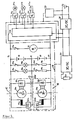
Figur 2 zeigt ein zweites Ausführungsbeispiel eines Bordnetzes für ein Kraftfahrzeug, das einige Details zeigt, die im Ausführungsbeispiel nach Figur 1 nicht explizit dargestellt wurden. Zwei Batterien 10 und 11 mit den Anschlußklemmen 12, 13 und 14 sind in Serie geschaltet. Zwischen die Klemmen 12 und 13 ist ein erster Generator 15, der die Batterie 10 mit Spannung versorgt geschaltet, zwischen die Klemmen 13 und 14 ein zweiter Generator 16, der die Batterie 11 mit Spannung versorgt. An die erste Batterie 10 sind über Schalter 27a und 27b zwei Glühlampen 19a und 19b an die Anschlußklemmen 12 und 13 angeschlossen. An die Batterie 11 sind Verbraucher 20a und 20b über Schalter 27c und 27d mit den Klemmen 13 und 14 verbunden. Die Anschlußklemme 13 ist weiterhin mit Masse verbunden. Über einen weiteren Schalter 27e ist der Starter 26 mit der Klemme 12 der Batterie 10 und der Klemme 14 der Batterie 11 verbunden. Mit denselben Klemmen 12 und 14 ist ein Spannungsringnetz 28 z.B. Multiplex-Ringnetz verbunden, das über Bauelemente 23a, b, c Verbraucher 21a, b, c mit Spannung versorgt. Diese Bauelemente 23 werden mit Hilfe einer elektronischen Schaltung 37, die mit den Bauelementen 23a, b, c über eine Datenringleitung 29 verbunden ist, gesteuert. Die elektronische Schaltung 37 steuert weiterhin einen DC/DC-Wandler 38 sowie einen DC/AC-Wandler 39, die beide über das Ringnetz 28 mit Spannung versorgt werden. An den DC/AC-Wandler ist eine Heizscheibe 40 angeschlossen, die mit einer 80 Volt, 1 kHz-Wechselspannung betrieben wird. Der DC/DC-Wandler liefert eine 5 Volt Gleichspannung, die an einer Batterie 32 anliegt und die die elektronische Schaltung 37 mit Spannung versorgt. Statt über eine Spannungsringleitung kann die Spannungsversorgung der Verbraucher auch mittels eines Strahlen- oder Maschennetzes bewerkstelligt werden.Figure 2 shows a second embodiment of an electrical system for a motor vehicle, which shows some details that were not explicitly shown in the embodiment of Figure 1. Two
Bei diesem Ausführungsbeispiel liegt der Starter 26 an der Gesamtspannung, die zwischen den Klemmen 12 und 14 anliegt.In this embodiment, the
Über die Datenringleitung 29 sind die einzelnen Bauelemente der Schaltung untereinander verbunden und werden mit Hilfe der elektronischen Schaltung 37 gesteuert.The individual components of the circuit are connected to one another via the data ring line 29 and are controlled by means of the
Die Generatoren 15 und 16 beider Ausführungsbeispiele sind Wechselstromgeneratoren, von denen einer beispielsweise als permanenterregter Generator ausgebildet ist und somit als "Grundlast-Generator" geeignet ist, und enthalten jeweils Feldwicklungen 33a, b und Ankerwicklungen 34a, b. Die Ausgangsspanung wird mittels zweier Regler 35a, 35b auf dem gewünschgten Wert gehalten. Die Ausgangsspanung wird jeweils in Gleichrichtersysstemen 36a, b gleichgerichtet, bevor sie ins Bordnetz eingespeist wird.The
Neben der Spannungserzeugung duch zwei einzelne Generatoren, die gegebenenfalls über eine Kupplung miteinander verbunden sind, ist es auch möglich einen Doppelgenerator mit zwei Systemen, beispielsweise 1x12 Volt und 1x24 Volt zu verwenden.In addition to the voltage generation by means of two individual generators, which may be connected to one another via a coupling, it is also possible to use a double generator with two systems, for example 1x12 volts and 1x24 volts.
Ein Antrieb der zwei Generatoren kann über einen Multirippenriemen erfolgen, er reduziert damit die pro Generator erforderlichen Momente und verteilt die Riemenkräfte auf verschiedene Riemenabschnitte.The two generators can be driven by a multi-ribbed belt, thus reducing the torque required per generator and distributing the belt forces to different belt sections.
Auch ein Generator mit höherer Nennspannung, beispielsweise 36 Volt, der mittels einer elektronischen Schaltung (Symmmetrierschaltung)beide Batterien, beispielsweise eine 12 Volt Batterie und eine 24 Volt Batterie mit Spannung versorgt, kann zur Spannungserzeugung eingesetzt werden.A generator with a higher nominal voltage, for example 36 volts, which supplies both batteries, for example a 12 volt battery and a 24 volt battery, with an electronic circuit (balancing circuit), can be used to generate the voltage.
Claims (19)
Applications Claiming Priority (2)
| Application Number | Priority Date | Filing Date | Title |
|---|---|---|---|
| DE3812577 | 1988-04-15 | ||
| DE3812577A DE3812577A1 (en) | 1988-04-15 | 1988-04-15 | ON-BOARD NETWORK FOR A MOTOR VEHICLE |
Publications (3)
| Publication Number | Publication Date |
|---|---|
| EP0337155A2 true EP0337155A2 (en) | 1989-10-18 |
| EP0337155A3 EP0337155A3 (en) | 1990-01-17 |
| EP0337155B1 EP0337155B1 (en) | 1992-12-23 |
Family
ID=6352075
Family Applications (1)
| Application Number | Title | Priority Date | Filing Date |
|---|---|---|---|
| EP89104852A Expired - Lifetime EP0337155B1 (en) | 1988-04-15 | 1989-03-17 | Power supply network for vehicle |
Country Status (3)
| Country | Link |
|---|---|
| EP (1) | EP0337155B1 (en) |
| JP (1) | JPH01308133A (en) |
| DE (2) | DE3812577A1 (en) |
Cited By (4)
| Publication number | Priority date | Publication date | Assignee | Title |
|---|---|---|---|---|
| EP0464694A2 (en) * | 1990-06-28 | 1992-01-08 | Nippondenso Co., Ltd. | Power source unit for an automotive vehicle |
| EP0569278A1 (en) * | 1992-05-07 | 1993-11-10 | Valeo Equipements Electriques Moteur | Electrical high-tension supply device of an auxiliary circuit of a vehicle |
| WO2000076812A1 (en) * | 1999-06-09 | 2000-12-21 | Lear Automotive (Eeds) Spain, S.L. | Electrical distribution box for vehicles having two networks with different voltage levels |
| WO2001032473A1 (en) * | 1999-11-05 | 2001-05-10 | Volkswagen Aktiengesellschaft | Motor vehicle electrical system |
Families Citing this family (22)
| Publication number | Priority date | Publication date | Assignee | Title |
|---|---|---|---|---|
| DE4041220A1 (en) * | 1990-12-21 | 1992-07-02 | Vogt Electronic Ag | POWER SUPPLY FOR MOTOR VEHICLES |
| DE4108861C2 (en) * | 1991-03-19 | 2002-06-27 | Bosch Gmbh Robert | Device for power supply in a motor vehicle with generators connected in parallel |
| JP3099405B2 (en) * | 1991-04-24 | 2000-10-16 | 株式会社デンソー | Power supply for vehicles |
| US6218643B1 (en) * | 1991-07-18 | 2001-04-17 | Mitsubishi Denki Kabushiki Kaisha | Power supplying apparatus for automotive part |
| DE4138943C1 (en) * | 1991-11-27 | 1993-05-27 | Robert Bosch Gmbh, 7000 Stuttgart, De | |
| JP3039119B2 (en) * | 1992-03-31 | 2000-05-08 | 日産自動車株式会社 | Power supply for vehicles |
| DE4300535A1 (en) * | 1993-01-12 | 1994-07-14 | Wuerth Elektronik Gmbh & Co Kg | Electrical load-to-one-of-several voltage-sources connector for commercial vehicle |
| DE19609009A1 (en) * | 1996-03-08 | 1997-09-11 | Edag Eng & Design Ag | Electrical power supply to several loads |
| DE19720816A1 (en) * | 1997-05-16 | 1998-11-19 | Wegmann & Co Gmbh | Electrical supply device for a military vehicle, in particular for a tank provided with a turret |
| DE19752661C2 (en) † | 1997-11-27 | 2001-09-13 | Siemens Ag | Vehicle electrical system for a motor vehicle |
| DE19907852A1 (en) * | 1999-02-24 | 2000-08-31 | Bayerische Motoren Werke Ag | Generator system for vehicle, has generators driven by drive unit that can be operated at different revolution rates, and different transmission ratios of at least two generators with respect to drive unit are selected |
| DE19930017A1 (en) * | 1999-06-30 | 2001-01-04 | Volkswagen Ag | Device for generating voltage in a motor vehicle |
| DE10042524A1 (en) * | 2000-08-30 | 2002-03-28 | Audi Ag | Vehicle power supply with two generators and two distribution networks, includes super-capacity condenser supplying energy converter |
| DE10106723B4 (en) * | 2001-02-14 | 2005-01-27 | Robert Bosch Gmbh | Device for supplying energy to a plurality of voltage supply systems and batteries |
| DE10131435A1 (en) * | 2001-06-29 | 2002-06-27 | Daimler Chrysler Ag | Automobile with two on-board electrical systems with different voltages has first battery and protection unit in front space and second battery, fuse unit and converter in rear space |
| JP2003235176A (en) * | 2002-02-07 | 2003-08-22 | Sumitomo Electric Ind Ltd | Charging system for battery |
| DE10304764B3 (en) | 2003-02-05 | 2004-02-26 | Daimlerchrysler Ag | Dual-voltage onboard electrical network for automobile has 2 series batteries connected in parallel for emergency starting and used for providing emergency running upon failure of generator or DC/DC converter |
| DE10338160A1 (en) * | 2003-08-20 | 2005-03-24 | Audi Ag | Voltage supply unit for a motor vehicle has two generators on a common shaft supplying different circuits with one providing a higher voltage than the other |
| DE102004008433A1 (en) | 2004-02-19 | 2005-09-08 | Robert Bosch Gmbh | Device for power supply |
| US9240685B2 (en) * | 2013-01-21 | 2016-01-19 | Hamilton Sundstrand Corporation | Reconfigurable matrix-based power distribution architecture |
| DE102015208542A1 (en) * | 2015-05-07 | 2016-09-08 | Continental Automotive Gmbh | Supply device for a vehicle electrical system and electrical system with supply device |
| US11001213B2 (en) | 2019-07-17 | 2021-05-11 | Ford Global Technologies, Llc | Onboard AC generator for power-to-the-box in vehicles with combustion engine |
Citations (5)
| Publication number | Priority date | Publication date | Assignee | Title |
|---|---|---|---|---|
| US4045718A (en) * | 1975-04-02 | 1977-08-30 | Maremont Corporation | Multiple winding multiple voltage alternator electrical supply system |
| GB1585915A (en) * | 1977-07-26 | 1981-03-11 | Scheidler R | Dual battery charge control |
| DE3007941A1 (en) * | 1980-03-01 | 1981-09-17 | Robert Bosch Gmbh, 7000 Stuttgart | Dual voltage supply system for vehicle - produces high charging volts for battery and constant volts for lights |
| US4604565A (en) * | 1982-05-20 | 1986-08-05 | Mitsubishi Denki Kabushiki Kaisha | Microcomputer-controlled DC three-wire circuit for vehicle |
| EP0232828A2 (en) * | 1986-02-14 | 1987-08-19 | Hitachi, Ltd. | Vehicular power supply system having a plurality of power supply voltages |
-
1988
- 1988-04-15 DE DE3812577A patent/DE3812577A1/en not_active Withdrawn
-
1989
- 1989-03-17 EP EP89104852A patent/EP0337155B1/en not_active Expired - Lifetime
- 1989-03-17 DE DE8989104852T patent/DE58903070D1/en not_active Expired - Fee Related
- 1989-04-14 JP JP1093283A patent/JPH01308133A/en active Pending
Patent Citations (5)
| Publication number | Priority date | Publication date | Assignee | Title |
|---|---|---|---|---|
| US4045718A (en) * | 1975-04-02 | 1977-08-30 | Maremont Corporation | Multiple winding multiple voltage alternator electrical supply system |
| GB1585915A (en) * | 1977-07-26 | 1981-03-11 | Scheidler R | Dual battery charge control |
| DE3007941A1 (en) * | 1980-03-01 | 1981-09-17 | Robert Bosch Gmbh, 7000 Stuttgart | Dual voltage supply system for vehicle - produces high charging volts for battery and constant volts for lights |
| US4604565A (en) * | 1982-05-20 | 1986-08-05 | Mitsubishi Denki Kabushiki Kaisha | Microcomputer-controlled DC three-wire circuit for vehicle |
| EP0232828A2 (en) * | 1986-02-14 | 1987-08-19 | Hitachi, Ltd. | Vehicular power supply system having a plurality of power supply voltages |
Cited By (7)
| Publication number | Priority date | Publication date | Assignee | Title |
|---|---|---|---|---|
| EP0464694A2 (en) * | 1990-06-28 | 1992-01-08 | Nippondenso Co., Ltd. | Power source unit for an automotive vehicle |
| EP0464694A3 (en) * | 1990-06-28 | 1993-03-31 | Nippondenso Co., Ltd. | Power source unit for an automotive vehicle |
| EP0569278A1 (en) * | 1992-05-07 | 1993-11-10 | Valeo Equipements Electriques Moteur | Electrical high-tension supply device of an auxiliary circuit of a vehicle |
| FR2690889A1 (en) * | 1992-05-07 | 1993-11-12 | Valeo Equip Electr Moteur | High voltage power supply device for an auxiliary circuit of a motor vehicle. |
| WO2000076812A1 (en) * | 1999-06-09 | 2000-12-21 | Lear Automotive (Eeds) Spain, S.L. | Electrical distribution box for vehicles having two networks with different voltage levels |
| US6879057B1 (en) | 1999-06-09 | 2005-04-12 | Lear Automotive (Eeds) Spain, S.L. | Electrical distribution box for vehicles having two networks with different voltage levels |
| WO2001032473A1 (en) * | 1999-11-05 | 2001-05-10 | Volkswagen Aktiengesellschaft | Motor vehicle electrical system |
Also Published As
| Publication number | Publication date |
|---|---|
| EP0337155B1 (en) | 1992-12-23 |
| JPH01308133A (en) | 1989-12-12 |
| EP0337155A3 (en) | 1990-01-17 |
| DE3812577A1 (en) | 1989-10-26 |
| DE58903070D1 (en) | 1993-02-04 |
Similar Documents
| Publication | Publication Date | Title |
|---|---|---|
| EP0337155B1 (en) | Power supply network for vehicle | |
| DE3743317C2 (en) | ||
| DE102018108383A1 (en) | INTEGRATED SOLAR COLLECTOR POWER POINT TRACKER IN AN ELECTRIC VEHICLE SYSTEM | |
| DE2650851A1 (en) | POWER SUPPLY DEVICE FOR A DUAL-VOLTAGE SYSTEM IN A MOTOR VEHICLE | |
| DE10148248A1 (en) | Method and electrical system for power efficient vehicle battery charging with generator operating at full power when charging | |
| US4100474A (en) | Multi-voltage vehicular network system | |
| DE102012203612A1 (en) | Battery charger for charging high and low-voltage batteries in e.g. electric vehicle, provides first charging voltage to first battery at output terminals and second charging voltage to second battery at secondary-side rectifier output | |
| DE3719376A1 (en) | POWER GENERATOR | |
| DE102010017417A1 (en) | Electric supply and starting system for a motor vehicle and method for operating the electrical supply and starting system | |
| DE3801478C2 (en) | Power supply circuit for a motor vehicle with two different consumer voltages | |
| DE69630231T2 (en) | Supply unit for an electric vehicle | |
| DE3007941C2 (en) | ||
| DE10148247A1 (en) | Method for charging an energy storage device and system for power output with pulse charging for a vehicle | |
| DE4226311A1 (en) | Three=phase current generator for vehicle - uses voltage between star-point and earth (roughly half line voltage) to power auxiliaries in vehicle | |
| EP0386055B1 (en) | Vehicle circuit systems | |
| DE10232416B4 (en) | Circuit arrangement and method for stabilizing a supply voltage | |
| DE19953373B4 (en) | Device for power supply in a motor vehicle | |
| EP1145913A2 (en) | Vehicle power supply with voltage stabiliser | |
| DE3142878A1 (en) | On-board power supply generator for vehicles | |
| DE10106723B4 (en) | Device for supplying energy to a plurality of voltage supply systems and batteries | |
| DE2735114A1 (en) | Dual battery charge control - directs current into battery giving lowest voltage using turn-on control for SCRs | |
| EP0760312B1 (en) | Circuit for the power supply of consumers | |
| EP3316432A1 (en) | Power supply device with an interface for operating a multi-voltage system | |
| EP1834842B1 (en) | Power supply device for a commercial vehicle | |
| DE605925C (en) | Device for keeping the auxiliary mains voltage constant on diesel-electric vehicles |
Legal Events
| Date | Code | Title | Description |
|---|---|---|---|
| PUAI | Public reference made under article 153(3) epc to a published international application that has entered the european phase |
Free format text: ORIGINAL CODE: 0009012 |
|
| AK | Designated contracting states |
Kind code of ref document: A2 Designated state(s): DE FR GB IT |
|
| PUAL | Search report despatched |
Free format text: ORIGINAL CODE: 0009013 |
|
| AK | Designated contracting states |
Kind code of ref document: A3 Designated state(s): DE FR GB IT |
|
| 17P | Request for examination filed |
Effective date: 19900629 |
|
| 17Q | First examination report despatched |
Effective date: 19910424 |
|
| RAP3 | Party data changed (applicant data changed or rights of an application transferred) |
Owner name: ROBERT BOSCH GMBH |
|
| GRAA | (expected) grant |
Free format text: ORIGINAL CODE: 0009210 |
|
| AK | Designated contracting states |
Kind code of ref document: B1 Designated state(s): DE FR GB IT |
|
| ET | Fr: translation filed | ||
| GBT | Gb: translation of ep patent filed (gb section 77(6)(a)/1977) |
Effective date: 19921222 |
|
| REF | Corresponds to: |
Ref document number: 58903070 Country of ref document: DE Date of ref document: 19930204 |
|
| ITF | It: translation for a ep patent filed |
Owner name: STUDIO JAUMANN |
|
| PLBE | No opposition filed within time limit |
Free format text: ORIGINAL CODE: 0009261 |
|
| STAA | Information on the status of an ep patent application or granted ep patent |
Free format text: STATUS: NO OPPOSITION FILED WITHIN TIME LIMIT |
|
| 26N | No opposition filed | ||
| PGFP | Annual fee paid to national office [announced via postgrant information from national office to epo] |
Ref country code: GB Payment date: 19990302 Year of fee payment: 11 |
|
| PGFP | Annual fee paid to national office [announced via postgrant information from national office to epo] |
Ref country code: FR Payment date: 19990323 Year of fee payment: 11 |
|
| PG25 | Lapsed in a contracting state [announced via postgrant information from national office to epo] |
Ref country code: GB Free format text: LAPSE BECAUSE OF NON-PAYMENT OF DUE FEES Effective date: 20000317 |
|
| GBPC | Gb: european patent ceased through non-payment of renewal fee |
Effective date: 20000317 |
|
| PG25 | Lapsed in a contracting state [announced via postgrant information from national office to epo] |
Ref country code: FR Free format text: LAPSE BECAUSE OF NON-PAYMENT OF DUE FEES Effective date: 20001130 |
|
| REG | Reference to a national code |
Ref country code: FR Ref legal event code: ST |
|
| PG25 | Lapsed in a contracting state [announced via postgrant information from national office to epo] |
Ref country code: IT Free format text: LAPSE BECAUSE OF NON-PAYMENT OF DUE FEES;WARNING: LAPSES OF ITALIAN PATENTS WITH EFFECTIVE DATE BEFORE 2007 MAY HAVE OCCURRED AT ANY TIME BEFORE 2007. THE CORRECT EFFECTIVE DATE MAY BE DIFFERENT FROM THE ONE RECORDED. Effective date: 20050317 |
|
| PGFP | Annual fee paid to national office [announced via postgrant information from national office to epo] |
Ref country code: DE Payment date: 20060516 Year of fee payment: 18 |
|
| PG25 | Lapsed in a contracting state [announced via postgrant information from national office to epo] |
Ref country code: DE Free format text: LAPSE BECAUSE OF NON-PAYMENT OF DUE FEES Effective date: 20071002 |