EP0336519B1 - Prüfsystem für Caissons und Rammpfähle - Google Patents
Prüfsystem für Caissons und Rammpfähle Download PDFInfo
- Publication number
- EP0336519B1 EP0336519B1 EP89200860A EP89200860A EP0336519B1 EP 0336519 B1 EP0336519 B1 EP 0336519B1 EP 89200860 A EP89200860 A EP 89200860A EP 89200860 A EP89200860 A EP 89200860A EP 0336519 B1 EP0336519 B1 EP 0336519B1
- Authority
- EP
- European Patent Office
- Prior art keywords
- foundation element
- force
- inertial mass
- carrier
- base
- Prior art date
- Legal status (The legal status is an assumption and is not a legal conclusion. Google has not performed a legal analysis and makes no representation as to the accuracy of the status listed.)
- Expired - Lifetime
Links
- 238000012360 testing method Methods 0.000 title claims abstract description 20
- 238000006243 chemical reaction Methods 0.000 claims abstract description 29
- 239000003380 propellant Substances 0.000 claims abstract description 19
- 239000012530 fluid Substances 0.000 claims abstract description 15
- 239000007789 gas Substances 0.000 claims description 16
- 238000006073 displacement reaction Methods 0.000 claims description 13
- 238000002485 combustion reaction Methods 0.000 claims description 11
- 238000000034 method Methods 0.000 claims description 11
- 230000005484 gravity Effects 0.000 claims description 6
- 239000000567 combustion gas Substances 0.000 claims description 5
- 230000000694 effects Effects 0.000 claims description 4
- 150000001875 compounds Chemical class 0.000 claims description 3
- 230000001133 acceleration Effects 0.000 claims description 2
- 238000013270 controlled release Methods 0.000 claims 1
- 238000010998 test method Methods 0.000 abstract description 8
- 230000006378 damage Effects 0.000 abstract description 4
- 230000003584 silencer Effects 0.000 description 7
- 238000013461 design Methods 0.000 description 6
- 229910000831 Steel Inorganic materials 0.000 description 5
- 239000000463 material Substances 0.000 description 5
- 239000010959 steel Substances 0.000 description 5
- 239000004576 sand Substances 0.000 description 4
- 239000002689 soil Substances 0.000 description 4
- 230000000977 initiatory effect Effects 0.000 description 3
- RYGMFSIKBFXOCR-UHFFFAOYSA-N Copper Chemical compound [Cu] RYGMFSIKBFXOCR-UHFFFAOYSA-N 0.000 description 2
- 230000015572 biosynthetic process Effects 0.000 description 2
- 229910052802 copper Inorganic materials 0.000 description 2
- 239000010949 copper Substances 0.000 description 2
- 238000012956 testing procedure Methods 0.000 description 2
- 238000004891 communication Methods 0.000 description 1
- 239000004020 conductor Substances 0.000 description 1
- 238000010276 construction Methods 0.000 description 1
- 238000007796 conventional method Methods 0.000 description 1
- 230000003467 diminishing effect Effects 0.000 description 1
- 238000009429 electrical wiring Methods 0.000 description 1
- 230000003628 erosive effect Effects 0.000 description 1
- 238000011065 in-situ storage Methods 0.000 description 1
- 238000009434 installation Methods 0.000 description 1
- 238000005007 materials handling Methods 0.000 description 1
- 230000003014 reinforcing effect Effects 0.000 description 1
- 231100000817 safety factor Toxicity 0.000 description 1
- 238000007789 sealing Methods 0.000 description 1
- XLYOFNOQVPJJNP-UHFFFAOYSA-N water Substances O XLYOFNOQVPJJNP-UHFFFAOYSA-N 0.000 description 1
Images
Classifications
-
- G—PHYSICS
- G01—MEASURING; TESTING
- G01M—TESTING STATIC OR DYNAMIC BALANCE OF MACHINES OR STRUCTURES; TESTING OF STRUCTURES OR APPARATUS, NOT OTHERWISE PROVIDED FOR
- G01M5/00—Investigating the elasticity of structures, e.g. deflection of bridges or air-craft wings
- G01M5/0041—Investigating the elasticity of structures, e.g. deflection of bridges or air-craft wings by determining deflection or stress
- G01M5/005—Investigating the elasticity of structures, e.g. deflection of bridges or air-craft wings by determining deflection or stress by means of external apparatus, e.g. test benches or portable test systems
-
- G—PHYSICS
- G01—MEASURING; TESTING
- G01M—TESTING STATIC OR DYNAMIC BALANCE OF MACHINES OR STRUCTURES; TESTING OF STRUCTURES OR APPARATUS, NOT OTHERWISE PROVIDED FOR
- G01M99/00—Subject matter not provided for in other groups of this subclass
Definitions
- This invention relates to a new or improved test system for caissons, piles and the like providing an improved process and apparatus for testing the load bearing capabilities of such inground foundation elements as defined in the preamble of claim 1 and 7.
- the capacity of foundation elements such as caissons can be further tested by either of two conventional techniques.
- a support structure is built spaced above the top end of the caisson and loaded with a large mass.
- steel beams and piles may be fabricated into a rough box-shaped structure which is then loaded with sand or concrete blocks.
- a hydraulic jack is then positioned between the top of the caisson and the underside of the support structure and is expanded to jack against the underside of the weighted structure and in this way apply a controllable downwardly directed reaction load to the caisson.
- large reaction forces may be produced, but the equipment is cumbersome, and accordingly the test procedure is time consuming and expensive.
- the second conventional test method involves the use of two auxiliary foundation elements spaced one on each side of the caisson to be tested.
- a large beam is then positioned to span across the three inline foundation elements and attached to the auxiliary foundation elements.
- a hydraulic jack is then placed between the top of the caisson to be tested and the underside of the beam in the center of the span.
- the ends of the beam being anchored to the auxiliary foundation elements apply the upwardly directed force of the jack to these in tension, the downwards reaction force of the jack being applied to the foundation element to be tested. In this way a high reaction force may be obtained.
- this test procedure is also time consuming and relatively expensive.
- the present invention provides a method for testing the load bearing capacity of a columnar inground foundation element, that is characterized in that a downwards force acting on the element is produced in a chamber defined between parts operatively associated with an inertial mass and the upper end of the foundation element respectively, by generating a rapidly increasing fluid pressure to produce an upwards acceleration of said inertial mass and a corresponding downwards reaction force of a predetermined desired magnitude on said foundation element, said fluid pressure being controlled such that the magnitude and rate of increase the downwards force are sufficient to effect downwards displacement of said foundation element without damaging the latter.
- the fluid pressure is preferably generated by the combustion of a propellant charge, with the inertial mass being guided to move upwards axially of the foundation element.
- the escape of the gases produced by the combustion is controlled in such a manner as to attenuate soundwaves produced by the combustion.
- the upper end of the foundation element will be protected from impact by the inertial mass when it descends under gravity after the fluid pressure has been dissipated.
- the apparatus of the present invention is characterized in that a carrier is configured to be seated coaxially on said base and is adapted to support an inertial mass of a desired magnitude; chamber means being defined between said base and said carrier and comprising a cylinder having opposite ends associated with said base and said carrier respectively, said chamber having a volume which increases as said carrier moves upwardly away from its seated position (Fig. 2) on said base ; pressure generating means for producing a controlled rapid increase in fluid pressure in said chamber of a magnitude sufficient to accelerate upwards said carrier and inertial mass and to produce a corresponding downwards reaction force on said base ; and pressure transducer means to measure continuously the magnitude of said downwards force as a function of said fluid pressure.
- the base has a central axial piston element received in a cylindrical bore opening from the underside of the carrier, the end of the piston being formed with a recess to receive a charge of a combustible propellant compound.
- the ignition means for this charge is arranged to be actuated from outside the cylinder.
- the inertial mass may be in the form of one or more toroidal rings, suitably of concrete, positioned around the exterior of the cylinder and thus aligned to the vertical axis of the foundation element.
- interpose sand or gravel between the underside of the carrier and the top of the base may be interpose sand or gravel between the underside of the carrier and the top of the base.
- an annual cavity may be provided surrounding the toroidal rings, and this cavity filled with gravel which will slump to spread under the carrier when the later is raised.
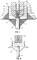
- a cast in place inground foundation column or cassion 10 that is to be tested has a disc-shaped steel plate 11 grouted to its upper end.
- a launching base 12 is bolted on top of the steel plate so that it is axially aligned with the caisson 10, the base having an annular flange 13 at its lower end, and an upwardly projecting piston 14 that is axially aligned with the caisson 10.
- the piston has a central counterbore 15 opening from its upper face to receive a propellant charge 16.
- a launch cylinder assembly 17 has a radially extending plate 18 at its lower end adapted to rest upon the flange 13 of the launching base as seen in Figure 1, and a cylindrical portion 19 projecting axially upwards beyond the plate 18 and terminating in an end wall 20.
- a cylindrical expandable chamber 21 is thus defined between this end wall 20 of the cylinder assembly, and the upper end of the piston 14.
- the launching base 12 and the cylinder assembly 17 are preferably fabricated in steel, there being a copper gas seal 22 and piston rings 51 of steel positioned to provide sealing between the cooperating cylindrical walls.
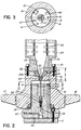
- An insert 23 is provided coaxially in a recess in the end wall 20 of the cylinder and defines an axial gas vent 23a extending therethrough.
- the insert 23 is fabricated in a suitable eroding combustible material such as copper and leads to a cylindrical silencer 24 positioned on top of the cylinder and fastened thereto by bolts 25.
- a replaceable annular throat 52 is seated above the insert 23 and has a conically widening bore 53 that communicates with a gas passage 26 in the lower end of the silencer.
- the gas passage 26 increases in cross section upwardly, is in register with the gas vent 23a, and is in communication with the interior of the silencer 24 which incorporates suitable sound attenuating means such as a system of baffles 54.
- the silencer 24 is generally of cylindrical form and has an outer diameter that corresponds to the outer diameter of the cylindrical portion 19 of the cylinder assembly 17.
- the upper side of the plate portion 18 of the launch cylinder is flat and is designed to provide a seat to support a reaction mass which is in the form of a plurality of toroidal concrete rings 30, these rings being aligned to the axis of the caisson 10 by the cylinder 19 and silencer 24.
- the above- described structure is surrounded by a mass of loose sand or gravel 31 that is contained within a cylindrical wall 32 spaced concentrically with respect to the rings 30.
- This wall 32 is supported on its outer lower side by a ring of backfill material 33, such material also surrounding the upper end of the caisson 10.
- the structure of the piston 14 is best illustrated in Figures 2 and 3 as comprising an axial bore 56 through which extends a vent rod 57 that is in threaded engagement with an insert 58 seated in the bore 56.
- the rod 57 passes through a seal structure 59, and then extends axially upwards through the propellant charge 16 received in the counterbore 15, through the gas vent 23a formed in the insert 23, and upwardly to a predetermined height X ( Figure 2) above the lower surface of the end wall 20 of the cylinder 19.
- three equiangularly spaced pressure transducers 61 are recessed in the top wall of the piston 14, these being connected to the exterior of the apparatus through suitable electrical wiring 62 passing through the flange 13 of the launching base 12 of the piston.
- the vent rod 57 is fabricated in a suitable electrically conductive material, and is utilized to transmit current to effect initiation of the propellant charge 16.
- an electrical connection 65 formed between the lower end of the vent rod 57 and the periphery of the flange 13, where it can be connected to external current supply means.
- a hot wire assembly 66 having three radial limbs of resistance wire is positioned between the vent rod 57 and surrounding portions of the end surface of the piston 14, the rod otherwise being insulated from the piston and from the cylinder assembly 17. It will be appreciated therefore that when current is applied to the connection 65 the hot wire assembly 66 will be heated and will effect initiation of the combustion of the propellant charge 16.
- the pressure transducers 61 monitor the pressure within the chamber 21 on a continuous basis.
- a velocity displacement transducer 34 is attached to the surface of the caisson to monitor displacements thereof.
- the cylinder bore 15 is loaded with a quantity of propellant charge 16 having combustion characteristics sufficient to generate the desired pressure in the chamber 21.
- the launch cylinder assembly 17 is then placed over the piston in the position shown in Figures 1 and 2 and loaded by the concrete rings 30 to provide a reaction mass of the desired magnitude.
- gas pressure in the chamber 21 increases very rapidly providing a force to launch the cylinder assembly 17 and its weight 30 vertically upwards, providing at the same time an equal and opposite downwardly acting reaction force upon the piston 14.
- This reaction force is of course coaxial with respect to the caisson 10 since the cylinder assembly is guided by the piston 14.
- the combustion gases are sealed within the chamber 21 since the vent 23a is closed by the vent rod 57 passing therethrough.
- the vent 23 is unblocked and permits escape of the combustion gases through the silencer 24.
- the flow of the hot combustion gases through the vent 23a rapidly erodes the material of the insert 23, widening the cross section of the vent 23a so that the gas pressure within the chamber 21 will dissipate relatively rapidly after combustion of the propellant 16 has been completed.
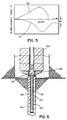
- Figure 4 shows schematically the arrangement after the cylinder assembly and the reaction mass have been launched. This will rise by no more than a few feet before beginning to descend again under the force of gravity. However before descent occurs, the surrounding mass of sand 31 will collapse under the plate 18 of the cylinder assembly and thus provide a cushion between this and the top of the caisson 10 when the cylinder assembly and reaction mass descend under the force of gravity. Thus impact damage to the caisson is avoided.
- the graph 40 in Figure 5 shows the change in pressure with time commencing with the initiation of combustion of the propellant charge as measured by the pressure transducer in the chamber 21, and the lower graph 41 shows the corresponding displacement of the top end of the caisson 10 as measured by the velocity transducer 34. It will be seen that as the pressure in the chamber 21 increases, the downwards displacement of the caisson 10 likewise increases, reaching a maximum at the same time as the chamber pressure, and thereafter diminishing, there being a residual displacement dx indicating that the frictional engagement between the caisson 10 and the surrounding ground formation has been stressed to failure point producing a permanent minor displacement of the caisson.
- the rate at which the pressure in the chamber 21 increases is a function of the characteristics of the propellant charge 16, and may be varied by appropriate selection of propellant materials.
- the desired reaction force should be developed over a duration of approximately 40 to 60 milliseconds which is almost 10 times longer than the duration of a force which could be achieved through impact of dropping a similar mass on top of the caisson 10.
- the duration over which the reaction force acts can be varied to some extent by variation in the length X by which the vent rod 57 projects. By increasing the dimension X, the duration of confinement of the combustion gases in the chamber 21 will be extended, and vice versa if the dimension X is reduced.
- the dimensions of the chamber 21 and the characteristics of the propellent charge 17 are preferably selected so that in operation a pressure of the order of 83.106 N/m2 (12,000 psi) is developed in the chamber.
- a relief passage 70 is provided in the cylinder end wall 20.
- the relief passage is sealed by a rupture disc 71 which is designed to fracture at some predetermined pressure, e.g. 103.106 N/m2 (15,000 psi), and vent gases from the chamber 21 through a passage 72 into the silencer 24.
- the invention provides a method of introducing high energies into the caisson 10 without damaging the latter.
- Reaction forces in the range 400 to 600 tons can be achieved by using a reaction mass that is of no more than 14500 kg (32,000 pounds) weight.
- the equipment consists essentially of the launching base 12, and the launch cylinder assembly 17, which is essentially of light weight and is easily transported.
- the concrete rings 30 forming the reaction mass weigh no more than 4540 kg (10,000 pounds) each, and in fact may readily be cast in situ at the same time as the test caisson itself is cast, and thus need not be transported from one site to another. It will be appreciated that because of the relatively low weights of the components, no special heavy weight materials handling equipment is necessary for installation of the test apparatus.
- test procedure can also be used in conjunction with the CAPWAPC (trademark) program to determine the capacity and distribution of resistance forces between the caisson 10 and the ground formation.
- FIG. 6 use is made of a relatively small diameter piston and cylinder having a long stroke.
- the elongated cylinder 17a having reinforcing ribs 17b thereon is cast in place within the upper end of the caisson 10a.
- An elongated piston 14a is received within the cylinder 17a and is connected at its upper end to a launch plate 18a on which the concrete rings 30a forming the reaction mass are supported.
- the launch plate 18a is secured to the end of the piston by frangible bolts 42.
- a slow burning propellant is provided in the elongate chamber 16a.
- the test system of the present invention provides a means by which caissons and piles can be load tested in a much cheaper and more convenient manner than was hitherto possible.
- a relatively small mass e.g. 8 cubic meters of concrete
- a relatively large reaction force up to 1,000 tons or more
- onsite full scale load testing can be performed in a relatively simple and inexpensive manner.
- This produces the overall benefit of being able to check accurately the load bearing capacity of a foundation member with reference to its designed load. Since such testing reveals excess capacity, substantial cost saving can be effected by modifying the foundation design.
- the CAPWAPC program in conjunction with the above described test procedure it is possible to determine the distribution shaft resistance in an accurate manner so that the foundation design can be fine tuned to eliminate factors of ignorance, yielding a safe adequate design without the excess cost of overdesign.
- the reaction force is concentric to the longitudinal axis of the caisson.
- the test procedure can be applied to caissons or batter piles that are positioned in the ground at an angle to the vertical, since the reaction force developed is in the direction of the axis of the foundation element, and is not significantly influenced by gravity.
- test procedure can be applied to foundation elements that are installed in the ground or in underwater sites. In the latter, the fluid resistance of the water will act to augment the inertial forces of the reaction mass, and thus a smaller mass may be utilized.
Landscapes
- Physics & Mathematics (AREA)
- General Physics & Mathematics (AREA)
- Engineering & Computer Science (AREA)
- Aviation & Aerospace Engineering (AREA)
- Investigating Strength Of Materials By Application Of Mechanical Stress (AREA)
- Testing Of Devices, Machine Parts, Or Other Structures Thereof (AREA)
- Revetment (AREA)
- Silver Salt Photography Or Processing Solution Therefor (AREA)
- Investigation Of Foundation Soil And Reinforcement Of Foundation Soil By Compacting Or Drainage (AREA)
- Force Measurement Appropriate To Specific Purposes (AREA)
Claims (14)
- Verfahren zum Testen der Lastaufnahmekapazität eines säulenartigen, in den Boden eingelassenen Fundamentbauteiles (10), bei dem eine träge Masse (30) vorgegebener Größe auf dem oberen Ende (11) des säulenartigen Fundamentbauteils (10), welches in den Boden eingebracht ist, abgestützt wird und die genannte träge Masse (30) verwendet wird, um eine nach unten gerichtete Kraft auf das Fundamentbauteil (10) aufzubringen und bei dem sowohl die Größe der nach unten gerichteten Kraft und der Reaktionskraft des Fundamentbauteils (10) gemessen werden,
dadurch gekennzeichnet,
daß die nach unten gerichtete Kraft in einer Kammer (21) erzeugt wird, die zwischen Teilen (17, 14) abgegrenzt ist, welche wirkungsmäßig verbunden sind mit der trägen Masse (30) bzw. dem oberen Ende des Fundamentbauteils (10), durch Erzeugung eines schnell wachsenden Fluid-Druckes, um eine nach oben gerichtete Beschleunigung der trägen Masse (30) und eine entsprechende nach unten gerichtete Reaktionskraft vorgegebener und erwünschter Größe am Fundamentbauteil (10) zu erzeugen, wobei der Fluid-Druck so gesteuert wird, daß die Größe und die Anstiegsrate der nach unten gerichteten Kraft ausreicht, um eine Verschiebung des Fundamentbauteils (10) nach unten zu erreichen, ohne es zu beschädigen. - Verfahren nach Anspruch 1, dadurch gekennzeichnet, daß der Fluid-Druck durch Verbrennung einer Treibstoffladung erzeugt wird.
- Verfahren nach einem der Ansprüche 1 oder 2, dadurch gekennzeichnet, daß die träge Masse (30) so geführt wird, daß sie sich axial aufwärts vom Fundamentbauteil (10) wegbewegt.
- Verfahren nach einem der Ansprüche 2 oder 3, dadurch gekennzeichnet, daß das Entweichen des durch die Verbrennung erzeugten Gases so gesteuert wird, daß die durch die Verbrennung erzeugten Schallwellen gedämpft werden.
- Verfahren nach einem der Ansprüche 1 bis 4, dadurch gekennzeichnet, daß das obere Ende des Fundamentbauteils (10) in bezug auf eine Einwirkung der trägen Masse (30) geschützt wird, wenn letztere nach Entfernung des Fluid-Druckes unter der Schwerkraft nach unten fällt.
- Verfahren nach einem der Ansprüche 1 bis 5, dadurch gekennzeichnet, daß die Größe der nach unten gerichteten Kraft und die dynamische Reaktion des Fundamentbauteils (10) auf kontinuierlicher Grundlage gemessen werden.
- Vorrichtung zum Testen der Lastaufnahmekapazität eines säulenartigen, in den Boden eingelassenen Fundamentbauteils (10), mit einer Basis (12), die so ausgestaltet ist, daß sie koaxial auf dem oberen Ende des Fundamentbauteils (10) befestigbar ist, und mit einer Einrichtung (21) zum Aufbringen einer nach unten gerichteten Kraft über die Basis (12) auf das Fundamentbauteil (10) und mit einer Verschiebungswandeleinrichtung (34) zum Messen der Reaktion des Bauteils (10) auf die Kraft, dadurch gekennzeichnet, daß ein Träger (17) so ausgeformt ist, daß er koaxial auf der genannten Basis (12) positionierbar ist und weiterhin eine träge Masse (30) einer gewünschten Größe abstützen kann; die Einrichtung (21) eine Kammer (21) aufweist, die zwischen der genannten Basis (12) und dem Träger (17) abgegrenzt ist und einen Zylinder mit gegenüberliegenden Enden (14, 20) aufweist, welche der Basis (12) bzw. dem Träger (17) zugeordnet sind, wobei die Kammer ein Volumen aufweist, das bei einer Bewegung des Trägers (17) aufwärts und weg von seiner Positionierstellung auf der Basis (12) ansteigt; daß eine Druckerzeugungseinrichtung (17, 57, 65) vorgesehen ist zum Erzeugen eines gesteuerten schnellen Anstiegs des Fluid-Drucks in der Kammer (21) von hinreichender Größe, um den Träger (17) und die träge Masse (30) aufwärts zu beschleunigen und um eine entsprechende nach unten gerichtete Reaktionskraft auf der Basis (12) zu erzeugen; und daß eine Druckwandeleinrichtung (61) vorgesehen ist, um kontinuierlich die Größe der nach unten gerichteten Kraft als Funktion des Fluiddruckes zu messen.
- Vorrichtung nach Anspruch 7, dadurch gekennzeichnet, daß die Basis (12) ein zentrales, axiales Kolbenbauteil (14) aufweist, welches gleitbar in einer Zylinderbohrung (21) aufgenommen ist, und zwar von der Unterseite des Trägers (17), daß die zylindrische Bohrung eine Endwand (20) aufweist, die ein Ende des Zylinders bildet, und daß das Ende des Kolbens (14) das gegenüberliegende Ende des Zylinders (21) bildet.
- Vorrichtung nach einem der Ansprüche 7 oder 8, dadurch gekennzeichnet, daß die Druckerzeugungseinrichtung eine Ladung (16) einer verbrennbaren Treibsatzverbindung aufweist.
- Vorrichtung nach Anspruch 8, dadurch gekennzeichnet, daß der Kolben (14) mit einer Ausnehmung (15) ausgeformt ist, die so ausgelegt ist, daß sie eine Druckerzeugungseinrichtung in Form einer Ladung (16) eines verbrennbaren Treibsatzes aufnimmt, und daß eine Zündeinrichtung (65, 57) für die Ladung vorgesehen ist und so ausgestaltet ist, daß sie von außerhalb des Zylinders betätigbar ist.
- Vorrichtung nach Anspruch 10, dadurch gekennzeichnet, daß ein Gasdurchlaß (23a) in der Endwand (20) der zylindrischen Bohrung (21) vorgesehen ist, um eine gesteuerte Freigabe von Verbrennungsgasen zu ermöglichen, die durch die Ladung (16) erzeugt werden.
- Vorrichtung nach Anspruch 11, dadurch gekennzeichnet, daß der Träger so ausgelegt ist, daß er eine träge Masse in Form von einem oder mehreren Toroid-Ringen (30) abstützt, die so ausgelegt sind, daß sie auf die vertikale Achse des Fundamentbauteils (10) durch Eingriff mit der Außenseite des Zylinders (19) ausrichtbar sind.
- Vorrichtung nach einem der Ansprüche 7 bis 12, dadurch gekennzeichnet, daß eine Einrichtung vorgesehen ist zum Verhindern eines Aufschlagens des Trägers (17) auf die Basis (12), wenn der Träger nach einer Aufwärtsbeschleunigung durch den Fluid-Druck unter der Schwerkraft wieder herunterfällt.
- Vorrichtung nach einem der Ansprüche 7 bis 13, dadurch gekennzeichnet, daß die Verschiebungswandlereinrichtung (34) so ausgelegt ist, daß sie die dynamische Reaktion des-Fundamentbauteils (10) auf eine solche abwärts gerichtete Kraft auf kontinuierlicher Grundlage mißt.
Priority Applications (1)
| Application Number | Priority Date | Filing Date | Title |
|---|---|---|---|
| AT89200860T ATE101268T1 (de) | 1988-04-07 | 1989-04-05 | Pruefsystem fuer caissons und rammpfaehle. |
Applications Claiming Priority (2)
| Application Number | Priority Date | Filing Date | Title |
|---|---|---|---|
| CA563495 | 1988-04-07 | ||
| CA000563495A CA1296925C (en) | 1988-04-07 | 1988-04-07 | Test system for caissons and piles |
Publications (3)
| Publication Number | Publication Date |
|---|---|
| EP0336519A2 EP0336519A2 (de) | 1989-10-11 |
| EP0336519A3 EP0336519A3 (de) | 1991-07-03 |
| EP0336519B1 true EP0336519B1 (de) | 1994-02-02 |
Family
ID=4137786
Family Applications (1)
| Application Number | Title | Priority Date | Filing Date |
|---|---|---|---|
| EP89200860A Expired - Lifetime EP0336519B1 (de) | 1988-04-07 | 1989-04-05 | Prüfsystem für Caissons und Rammpfähle |
Country Status (7)
| Country | Link |
|---|---|
| US (1) | US4845996A (de) |
| EP (1) | EP0336519B1 (de) |
| JP (1) | JPH0670602B2 (de) |
| AT (1) | ATE101268T1 (de) |
| CA (1) | CA1296925C (de) |
| DE (1) | DE68912806T2 (de) |
| ES (1) | ES2050779T3 (de) |
Families Citing this family (49)
| Publication number | Priority date | Publication date | Assignee | Title |
|---|---|---|---|---|
| US5259240A (en) * | 1992-04-03 | 1993-11-09 | Exxon Production Research Company | Device for in situ testing of soils that includes a vent valve adapted to close at a predetermined depth during installation |
| US6349590B1 (en) * | 1997-09-15 | 2002-02-26 | Yee Kong Wai | Method and apparatus for estimating load bearing capacity of piles |
| US6129487A (en) * | 1998-07-30 | 2000-10-10 | Bermingham Construction Limited | Underwater pile driving tool |
| US7192681B2 (en) | 2001-07-05 | 2007-03-20 | Fuji Photo Film Co., Ltd. | Positive photosensitive composition |
| JP4448705B2 (ja) | 2004-02-05 | 2010-04-14 | 富士フイルム株式会社 | 感光性組成物及び該感光性組成物を用いたパターン形成方法 |
| WO2006015278A2 (en) * | 2004-07-30 | 2006-02-09 | Loadtest, Inc. | Method and apparatus for automatic load testing using bi-directional testing |
| JP4602714B2 (ja) | 2004-08-19 | 2010-12-22 | 株式会社ティラド | 熱交換器 |
| JP4469692B2 (ja) | 2004-09-14 | 2010-05-26 | 富士フイルム株式会社 | 感光性組成物、該感光性組成物に用いられる化合物及び該感光性組成物を用いたパターン形成方法 |
| JP4474256B2 (ja) | 2004-09-30 | 2010-06-02 | 富士フイルム株式会社 | レジスト組成物及びそれを用いたパターン形成方法 |
| TWI530759B (zh) | 2005-01-24 | 2016-04-21 | 富士軟片股份有限公司 | 適用於浸漬曝光之正型光阻組成物及使用它之圖案形成方法 |
| JP4452632B2 (ja) | 2005-01-24 | 2010-04-21 | 富士フイルム株式会社 | 感光性組成物、該感光性組成物に用いる化合物及び該感光性組成物を用いたパターン形成方法 |
| JP4562537B2 (ja) | 2005-01-28 | 2010-10-13 | 富士フイルム株式会社 | 感光性組成物、該感光性組成物に用いる化合物及び該感光性組成物を用いたパターン形成方法 |
| US8741537B2 (en) | 2005-03-04 | 2014-06-03 | Fujifilm Corporation | Positive resist composition and pattern-forming method using the same |
| US7960087B2 (en) | 2005-03-11 | 2011-06-14 | Fujifilm Corporation | Positive photosensitive composition and pattern-forming method using the same |
| JP4579019B2 (ja) | 2005-03-17 | 2010-11-10 | 富士フイルム株式会社 | ポジ型レジスト組成物及び該レジスト組成物を用いたパターン形成方法 |
| EP1720072B1 (de) | 2005-05-01 | 2019-06-05 | Rohm and Haas Electronic Materials, L.L.C. | Zusammensetzungen und Verfahren für Immersionslithografie |
| JP4724465B2 (ja) | 2005-05-23 | 2011-07-13 | 富士フイルム株式会社 | 感光性組成物及び該感光性組成物を用いたパターン形成方法 |
| JP4861767B2 (ja) | 2005-07-26 | 2012-01-25 | 富士フイルム株式会社 | ポジ型レジスト組成物およびそれを用いたパターン形成方法 |
| JP4695941B2 (ja) | 2005-08-19 | 2011-06-08 | 富士フイルム株式会社 | 液浸露光用ポジ型レジスト組成物及びそれを用いたパターン形成方法 |
| TWI403843B (zh) | 2005-09-13 | 2013-08-01 | Fujifilm Corp | 正型光阻組成物及使用它之圖案形成方法 |
| EP1795960B1 (de) | 2005-12-09 | 2019-06-05 | Fujifilm Corporation | Positive Resistzusammensetzung, Verfahren zur Musterbildung unter Verwendung der positiven Resistzusammensetzung, Verwendung der positiven Resistzusammensetzung |
| JP4911456B2 (ja) | 2006-11-21 | 2012-04-04 | 富士フイルム株式会社 | ポジ型感光性組成物、該ポジ型感光性組成物に用いられる高分子化合物、該高分子化合物の製造方法及びポジ型感光性組成物を用いたパターン形成方法 |
| JP4554665B2 (ja) | 2006-12-25 | 2010-09-29 | 富士フイルム株式会社 | パターン形成方法、該パターン形成方法に用いられる多重現像用ポジ型レジスト組成物、該パターン形成方法に用いられるネガ現像用現像液及び該パターン形成方法に用いられるネガ現像用リンス液 |
| EP1962139A1 (de) | 2007-02-23 | 2008-08-27 | FUJIFILM Corporation | Negative Resistzusammensetzung und Verfahren zur Strukturformung damit |
| EP1975714A1 (de) | 2007-03-28 | 2008-10-01 | FUJIFILM Corporation | Positive Resistzusammensetzung und Verfahren zur Strukturformung |
| EP1975716B1 (de) | 2007-03-28 | 2013-05-15 | Fujifilm Corporation | Positive Resistzusammensetzung und Verfahren zur Strukturformung |
| EP1980911A3 (de) | 2007-04-13 | 2009-06-24 | FUJIFILM Corporation | Strukturformungsverfahren, in dem Strukturformungsverfahren zu verwendende Harzzusammensetzung, in dem Strukturformungsverfahren zu verwendende negative Entwicklungslösung und in dem Strukturformungsverfahren zu verwendende Spüllösung |
| EP2138898B1 (de) | 2007-04-13 | 2014-05-21 | FUJIFILM Corporation | Verfahren zur Strukturbildung und Verwendung einer Fotolackzusammensetzung in diesem Verfahren |
| JP4617337B2 (ja) | 2007-06-12 | 2011-01-26 | 富士フイルム株式会社 | パターン形成方法 |
| JP2008311474A (ja) | 2007-06-15 | 2008-12-25 | Fujifilm Corp | パターン形成方法 |
| US8088550B2 (en) | 2007-07-30 | 2012-01-03 | Fujifilm Corporation | Positive resist composition and pattern forming method |
| JP5066405B2 (ja) | 2007-08-02 | 2012-11-07 | 富士フイルム株式会社 | 電子線、x線又はeuv用レジスト組成物及び該組成物を用いたパターン形成方法 |
| EP2020617A3 (de) | 2007-08-03 | 2009-04-29 | FUJIFILM Corporation | Resistzusammensetzung mit einer Sulfoniumverbindung, Strukturbildungsverfahren mit der Resistzusammensetzung und Sulfoniumverbindung |
| JP5449675B2 (ja) | 2007-09-21 | 2014-03-19 | 富士フイルム株式会社 | 感光性組成物、該感光性組成物を用いたパターン形成方法及び該感光性組成物に用いられる化合物 |
| JP5150296B2 (ja) | 2008-02-13 | 2013-02-20 | 富士フイルム株式会社 | 電子線、x線またはeuv用ポジ型レジスト組成物及びこれを用いたパターン形成方法 |
| US9046773B2 (en) | 2008-03-26 | 2015-06-02 | Fujifilm Corporation | Actinic ray-sensitive or radiation-sensitive resin composition, pattern forming method using the same, polymerizable compound and polymer compound obtained by polymerizing the polymerizable compound |
| JP5997873B2 (ja) | 2008-06-30 | 2016-09-28 | 富士フイルム株式会社 | 感光性組成物及びそれを用いたパターン形成方法 |
| JP5244711B2 (ja) | 2008-06-30 | 2013-07-24 | 富士フイルム株式会社 | 感活性光線性または感放射線性樹脂組成物及びそれを用いたパターン形成方法 |
| JP5746818B2 (ja) | 2008-07-09 | 2015-07-08 | 富士フイルム株式会社 | 感活性光線性または感放射線性樹脂組成物及びそれを用いたパターン形成方法 |
| AU2009318200B2 (en) | 2008-11-21 | 2015-01-15 | Hadar Magali | Rebound-effector |
| KR101794035B1 (ko) | 2008-12-12 | 2017-11-06 | 후지필름 가부시키가이샤 | 감활성광선성 또는 감방사선성 수지 조성물 및 그것을 사용한 패턴형성방법 |
| KR101987730B1 (ko) | 2008-12-12 | 2019-06-11 | 후지필름 가부시키가이샤 | 감활성광선성 또는 감방사선성 수지 조성물 및 그 조성물을 이용한 패턴 형성 방법 |
| JP5377172B2 (ja) | 2009-03-31 | 2013-12-25 | 富士フイルム株式会社 | 感活性光線性又は感放射線性樹脂組成物及びそれを用いたパターン形成方法 |
| CA2732380C (en) * | 2010-02-22 | 2016-10-04 | Ben Kasprick | Method and apparatus for load testing a pile |
| US20120076996A1 (en) | 2010-09-28 | 2012-03-29 | Fujifilm Corporation | Resist composition, resist film therefrom and method of forming pattern therewith |
| CN105525635B (zh) * | 2016-01-18 | 2017-09-15 | 交通运输部公路科学研究所 | 用于桩基轴向承载力检测的加载装置 |
| CN106049562B (zh) * | 2016-07-18 | 2018-02-16 | 昆山市建设工程质量检测中心 | 一种用于桩基高应变检测的落锤高度调节装置 |
| KR20210074372A (ko) | 2018-11-22 | 2021-06-21 | 후지필름 가부시키가이샤 | 감활성광선성 또는 감방사선성 수지 조성물, 레지스트막, 패턴 형성 방법, 전자 디바이스의 제조 방법 |
| CN112525711B (zh) * | 2020-11-26 | 2023-08-22 | 中国电建集团成都勘测设计研究院有限公司 | 双向深部土体力学参数原位测试装置及测试结构 |
Family Cites Families (17)
| Publication number | Priority date | Publication date | Assignee | Title |
|---|---|---|---|---|
| US2674876A (en) * | 1950-08-28 | 1954-04-13 | Western Foundation Corp | Pile testing means |
| US3248924A (en) * | 1961-11-22 | 1966-05-03 | William W Boynton | System for dynamic loading |
| FR92879E (fr) * | 1966-09-23 | 1969-01-10 | Louis Francois | Procédé et appareil pour la mesure du module de déformation d'un matériau et des contraintes dans ce matériau. |
| GB1206396A (en) * | 1966-10-28 | 1970-09-23 | Wykeham Farrance Engineering L | Improvements relating to geological sample testing apparatus |
| US3535919A (en) * | 1968-12-02 | 1970-10-27 | John P Budlong | Dynamic determination of pile load capacity |
| DE2139735C3 (de) * | 1971-08-07 | 1974-02-21 | Rheinmetall Gmbh, 4000 Duesseldorf | Einrichtung zum Simulieren der Schußbeanspruchung von Geschützrohren |
| US3798962A (en) * | 1972-04-19 | 1974-03-26 | Atomic Energy Commission | Method for predicting movements of structural members emplaced in the earth |
| DE2439782B1 (de) * | 1974-08-20 | 1975-10-30 | Fa. Franz Gloetzl, 7501 Forchheim | Kraflmeßgerät für Anker im Bauwesen |
| US3960008A (en) * | 1974-12-12 | 1976-06-01 | Goble George G | Pile capacity testing means |
| FR2461066A1 (fr) * | 1979-07-09 | 1981-01-30 | Coelus Gaspar | Procede et appareil d'essai dynamique de pieux |
| US4347743A (en) * | 1980-09-18 | 1982-09-07 | Pile Dynamics, Inc. | Accelerometer mounting assembly |
| US4379401A (en) * | 1981-08-28 | 1983-04-12 | The United States Of America As Represented By The Secretary Of The Army | System for measuring plate deformation produced by explosive shock waves, and motion-sensing accelerometer transducer used therein |
| US4479378A (en) * | 1982-09-23 | 1984-10-30 | The United States Of America As Represented By The Secretary Of The Navy | Method and system for determining effect of underwater explosion on submerged structures |
| US4474052A (en) * | 1982-12-13 | 1984-10-02 | E. I. Du Pont De Nemours And Company | Laboratory barricade |
| JPS6080619A (ja) * | 1983-10-06 | 1985-05-08 | Inayoshi Kogyo:Kk | 杭打作業における打杭の支持力測定方法及びその装置 |
| US4619218A (en) * | 1984-01-30 | 1986-10-28 | Hen-Jac, Inc. | Embedment anchor |
| US4586366A (en) * | 1984-03-14 | 1986-05-06 | Milberger Lionel J | Method and apparatus for measuring driving resistance and velocity of piles during driving |
-
1988
- 1988-04-07 CA CA000563495A patent/CA1296925C/en not_active Expired - Lifetime
- 1988-05-04 US US07/190,163 patent/US4845996A/en not_active Expired - Lifetime
-
1989
- 1989-04-05 ES ES89200860T patent/ES2050779T3/es not_active Expired - Lifetime
- 1989-04-05 AT AT89200860T patent/ATE101268T1/de not_active IP Right Cessation
- 1989-04-05 EP EP89200860A patent/EP0336519B1/de not_active Expired - Lifetime
- 1989-04-05 DE DE68912806T patent/DE68912806T2/de not_active Expired - Fee Related
- 1989-04-07 JP JP1087126A patent/JPH0670602B2/ja not_active Expired - Lifetime
Also Published As
| Publication number | Publication date |
|---|---|
| EP0336519A2 (de) | 1989-10-11 |
| JPH0670602B2 (ja) | 1994-09-07 |
| CA1296925C (en) | 1992-03-10 |
| EP0336519A3 (de) | 1991-07-03 |
| JPH0228531A (ja) | 1990-01-30 |
| DE68912806T2 (de) | 1994-08-11 |
| ES2050779T3 (es) | 1994-06-01 |
| ATE101268T1 (de) | 1994-02-15 |
| DE68912806D1 (de) | 1994-03-17 |
| US4845996A (en) | 1989-07-11 |
Similar Documents
| Publication | Publication Date | Title |
|---|---|---|
| EP0336519B1 (de) | Prüfsystem für Caissons und Rammpfähle | |
| US4614110A (en) | Device for testing the load-bearing capacity of concrete-filled earthen shafts | |
| Engineer | An innovative approach to load testing of high capacity piles | |
| EP1102902B1 (de) | Unterwasserpfahlrammanlage | |
| US3946601A (en) | Method of load testing foundations | |
| FI92235B (fi) | Järjestelmä ankkurin työntämiseksi maahan | |
| US4132082A (en) | Piling | |
| US9581704B2 (en) | System and method for accelerating a mass using a pressure produced by a detonation | |
| JP4513092B2 (ja) | グラウンドアンカーの急速載荷試験装置 | |
| CN220305009U (zh) | 用于破碎岩体拱形承载结构锚固的试验装置 | |
| Beim et al. | Dynamic testing of enlarged base Franki piles | |
| Miyasaka et al. | Rapid load test on high bearing capacity piles | |
| Sloan | Dynamic Bearing Capacity of Soils: Dynamic Loading Machine and Preliminary Small-scale Footing Tests | |
| SU1756561A1 (ru) | Способ моделировани горного давлени и устройство дл его осуществлени | |
| EP1715105A1 (de) | Rammeinrichtung und Methode zur Einbringung von Fundamentelementen und Einsatz von Teilen zur Herstellung einer Rammeinrichtung | |
| Matsumoto et al. | Trend of research and practice of pile foundations in Japan | |
| JPS5836063Y2 (ja) | ジシンタンサヨウカシンソウチ | |
| Team | Lateral STATNAMIC Testing | |
| Robertson et al. | lateral load capacity | |
| WO1996020314A1 (en) | Transport means such as a vessel or vehicle, provided with a device for compacting ground | |
| Robertson et al. | Lateral STATNAMIC load testing: A new method for evaluating lateral load capacity | |
| Klishin | Tests of inertial devices to protect hydraulic props from dynamic loading | |
| GENERATOR | P. Lieberman, J. O'Neill, D. Freeman, A. Gibbs TRW Defense and Space Systems Group Redondo Beach, California 90278 | |
| Dowler et al. | Seismic vibration source | |
| Lewis et al. | Pressure Injected Footings–A Case History |
Legal Events
| Date | Code | Title | Description |
|---|---|---|---|
| PUAI | Public reference made under article 153(3) epc to a published international application that has entered the european phase |
Free format text: ORIGINAL CODE: 0009012 |
|
| AK | Designated contracting states |
Kind code of ref document: A2 Designated state(s): AT BE CH DE ES FR GB GR IT LI LU NL SE |
|
| PUAL | Search report despatched |
Free format text: ORIGINAL CODE: 0009013 |
|
| AK | Designated contracting states |
Kind code of ref document: A3 Designated state(s): AT BE CH DE ES FR GB GR IT LI LU NL SE |
|
| 17P | Request for examination filed |
Effective date: 19911220 |
|
| 17Q | First examination report despatched |
Effective date: 19921001 |
|
| GRAA | (expected) grant |
Free format text: ORIGINAL CODE: 0009210 |
|
| AK | Designated contracting states |
Kind code of ref document: B1 Designated state(s): AT BE CH DE ES FR GB GR IT LI LU NL SE |
|
| PG25 | Lapsed in a contracting state [announced via postgrant information from national office to epo] |
Ref country code: IT Free format text: LAPSE BECAUSE OF FAILURE TO SUBMIT A TRANSLATION OF THE DESCRIPTION OR TO PAY THE FEE WITHIN THE PRE;WARNING: LAPSES OF ITALIAN PATENTS WITH EFFECTIVE DATE BEFORE 2007 MAY HAVE OCCURRED AT ANY TIME BEFORE 2007. THE CORRECT EFFECTIVE DATE MAY BE DIFFERENT FROM THE ONE RECORDED.SCRIBED TIME-LIMIT Effective date: 19940202 Ref country code: GR Free format text: LAPSE BECAUSE OF FAILURE TO SUBMIT A TRANSLATION OF THE DESCRIPTION OR TO PAY THE FEE WITHIN THE PRESCRIBED TIME-LIMIT Effective date: 19940202 |
|
| REF | Corresponds to: |
Ref document number: 101268 Country of ref document: AT Date of ref document: 19940215 Kind code of ref document: T |
|
| REF | Corresponds to: |
Ref document number: 68912806 Country of ref document: DE Date of ref document: 19940317 |
|
| PG25 | Lapsed in a contracting state [announced via postgrant information from national office to epo] |
Ref country code: LU Free format text: LAPSE BECAUSE OF NON-PAYMENT OF DUE FEES Effective date: 19940430 |
|
| REG | Reference to a national code |
Ref country code: ES Ref legal event code: FG2A Ref document number: 2050779 Country of ref document: ES Kind code of ref document: T3 |
|
| ET | Fr: translation filed | ||
| PLBE | No opposition filed within time limit |
Free format text: ORIGINAL CODE: 0009261 |
|
| STAA | Information on the status of an ep patent application or granted ep patent |
Free format text: STATUS: NO OPPOSITION FILED WITHIN TIME LIMIT |
|
| 26N | No opposition filed | ||
| EAL | Se: european patent in force in sweden |
Ref document number: 89200860.8 |
|
| REG | Reference to a national code |
Ref country code: GB Ref legal event code: IF02 |
|
| PGFP | Annual fee paid to national office [announced via postgrant information from national office to epo] |
Ref country code: AT Payment date: 20030313 Year of fee payment: 15 |
|
| PGFP | Annual fee paid to national office [announced via postgrant information from national office to epo] |
Ref country code: CH Payment date: 20030331 Year of fee payment: 15 |
|
| PGFP | Annual fee paid to national office [announced via postgrant information from national office to epo] |
Ref country code: FR Payment date: 20030408 Year of fee payment: 15 |
|
| PGFP | Annual fee paid to national office [announced via postgrant information from national office to epo] |
Ref country code: ES Payment date: 20030411 Year of fee payment: 15 |
|
| PGFP | Annual fee paid to national office [announced via postgrant information from national office to epo] |
Ref country code: SE Payment date: 20030416 Year of fee payment: 15 |
|
| PGFP | Annual fee paid to national office [announced via postgrant information from national office to epo] |
Ref country code: DE Payment date: 20030424 Year of fee payment: 15 |
|
| PGFP | Annual fee paid to national office [announced via postgrant information from national office to epo] |
Ref country code: BE Payment date: 20030428 Year of fee payment: 15 |
|
| PG25 | Lapsed in a contracting state [announced via postgrant information from national office to epo] |
Ref country code: AT Free format text: LAPSE BECAUSE OF NON-PAYMENT OF DUE FEES Effective date: 20040405 |
|
| PG25 | Lapsed in a contracting state [announced via postgrant information from national office to epo] |
Ref country code: ES Free format text: LAPSE BECAUSE OF NON-PAYMENT OF DUE FEES Effective date: 20040406 Ref country code: SE Free format text: LAPSE BECAUSE OF NON-PAYMENT OF DUE FEES Effective date: 20040406 |
|
| PG25 | Lapsed in a contracting state [announced via postgrant information from national office to epo] |
Ref country code: LI Free format text: LAPSE BECAUSE OF NON-PAYMENT OF DUE FEES Effective date: 20040430 Ref country code: CH Free format text: LAPSE BECAUSE OF NON-PAYMENT OF DUE FEES Effective date: 20040430 Ref country code: BE Free format text: LAPSE BECAUSE OF NON-PAYMENT OF DUE FEES Effective date: 20040430 |
|
| BERE | Be: lapsed |
Owner name: *BERMINGHAMMER CORP. LTD Effective date: 20040430 |
|
| PG25 | Lapsed in a contracting state [announced via postgrant information from national office to epo] |
Ref country code: DE Free format text: LAPSE BECAUSE OF NON-PAYMENT OF DUE FEES Effective date: 20041103 |
|
| EUG | Se: european patent has lapsed | ||
| REG | Reference to a national code |
Ref country code: CH Ref legal event code: PL |
|
| PG25 | Lapsed in a contracting state [announced via postgrant information from national office to epo] |
Ref country code: FR Free format text: LAPSE BECAUSE OF NON-PAYMENT OF DUE FEES Effective date: 20041231 |
|
| REG | Reference to a national code |
Ref country code: FR Ref legal event code: ST |
|
| REG | Reference to a national code |
Ref country code: ES Ref legal event code: FD2A Effective date: 20040406 |
|
| PGFP | Annual fee paid to national office [announced via postgrant information from national office to epo] |
Ref country code: GB Payment date: 20080326 Year of fee payment: 20 |
|
| PGFP | Annual fee paid to national office [announced via postgrant information from national office to epo] |
Ref country code: NL Payment date: 20080430 Year of fee payment: 20 |
|
| REG | Reference to a national code |
Ref country code: GB Ref legal event code: PE20 Expiry date: 20090404 |
|
| PG25 | Lapsed in a contracting state [announced via postgrant information from national office to epo] |
Ref country code: NL Free format text: LAPSE BECAUSE OF EXPIRATION OF PROTECTION Effective date: 20090405 |
|
| NLV7 | Nl: ceased due to reaching the maximum lifetime of a patent |
Effective date: 20090405 |
|
| PG25 | Lapsed in a contracting state [announced via postgrant information from national office to epo] |
Ref country code: GB Free format text: LAPSE BECAUSE OF EXPIRATION OF PROTECTION Effective date: 20090404 |