EP0335700B1 - Kombination von Schalter und Sperrvorrichtung - Google Patents
Kombination von Schalter und Sperrvorrichtung Download PDFInfo
- Publication number
- EP0335700B1 EP0335700B1 EP89303121A EP89303121A EP0335700B1 EP 0335700 B1 EP0335700 B1 EP 0335700B1 EP 89303121 A EP89303121 A EP 89303121A EP 89303121 A EP89303121 A EP 89303121A EP 0335700 B1 EP0335700 B1 EP 0335700B1
- Authority
- EP
- European Patent Office
- Prior art keywords
- switch
- actuator
- linking member
- linking
- end portion
- Prior art date
- Legal status (The legal status is an assumption and is not a legal conclusion. Google has not performed a legal analysis and makes no representation as to the accuracy of the status listed.)
- Expired - Lifetime
Links
Images






Classifications
-
- B—PERFORMING OPERATIONS; TRANSPORTING
- B25—HAND TOOLS; PORTABLE POWER-DRIVEN TOOLS; MANIPULATORS
- B25B—TOOLS OR BENCH DEVICES NOT OTHERWISE PROVIDED FOR, FOR FASTENING, CONNECTING, DISENGAGING, OR HOLDING
- B25B23/00—Details of, or accessories for, spanners, wrenches, screwdrivers
- B25B23/14—Arrangement of torque limiters or torque indicators in wrenches or screwdrivers
- B25B23/147—Arrangement of torque limiters or torque indicators in wrenches or screwdrivers specially adapted for electrically operated wrenches or screwdrivers
-
- H—ELECTRICITY
- H01—ELECTRIC ELEMENTS
- H01H—ELECTRIC SWITCHES; RELAYS; SELECTORS; EMERGENCY PROTECTIVE DEVICES
- H01H35/00—Switches operated by change of a physical condition
- H01H35/006—Switches operated by mechanical overload condition, e.g. transmitted force or torque becoming too high
-
- H—ELECTRICITY
- H01—ELECTRIC ELEMENTS
- H01H—ELECTRIC SWITCHES; RELAYS; SELECTORS; EMERGENCY PROTECTIVE DEVICES
- H01H9/00—Details of switching devices, not covered by groups H01H1/00 - H01H7/00
- H01H9/02—Bases, casings, or covers
- H01H9/06—Casing of switch constituted by a handle serving a purpose other than the actuation of the switch, e.g. by the handle of a vacuum cleaner
Definitions
- the present invention relates to a switching device as defined in the pre-characterising portion of Claim 1.
- a switching device of conventional type according to the pre-characterising portion of Claim 1 is, for example, known from US-A-3 786 286.
- Some types of power tools such as electric screwdrivers, electric drills, electric circular saws and electric jigsaws incorporate a mechanism which is adapted to forcibly turn off a power switch for an electric motor when overload is imposed on a driver bit, drill bit or the like to produce excessive torque between the bit or the like and the output shaft of the electric motor.
- the mechanism is required to forcibly turn off the power switch of the motor on the occurrence of overload, even if an operating member or lever is held in such a position as to rotate the motor.
- the mechanism simultaneously produces dynamic braking force, for example, by forming a short circuit across armature coils.
- the mechanism must be so designed that when the operating member or lever is once shifted to its inoperative position and then returned to its operative position, the power switch of the motor may be turned on by means of the operating lever shifted to the operative position.
- the conventional mechanism of this type includes a circuit shown in FIG. 21.
- the circuit has two switches 1 and 3 connected between a power source 2 and a motor 4.
- the switch 1 is a starting switch for the motor adapted to be changed over in direct association with operation of the operating lever.
- the switch 1 has a contact c which is connected to a contact a and disconnected from the other contact b, when the operating lever is in its operative position.
- the contact c is disconnected from the contact a and connected to the contact b.
- the switch 3 is a locking switch adapted to be changed over in operative association with an overload sensing mechanism (not shown).
- the switch 3 has a contact f which is, with no overload sensed, connected to a contact d and disconnected from the other contact e. On the other hand, when overload is sensed, the contact f is disconnected from the contact d and connected to the contact e.
- the locking switch 3 may be of the type in which when overload is sensed by the overload sensing mechanism, the contact f is disconnected from the contact d, and when the operating lever is shifted to the inoperative position, the contact f is brought into contact with the contact d. In this case, if the operating lever is once shifted to the inoperative position and then returned to the operative position, driving current is supplied to the motor 4 to rotate the same.
- the conventional power tool having an overload cutoff feature includes two switches, that is, a starting switch (switch 1 in FIG. 21) for rotating the motor and a locking switch (switch 3 in FIG. 21) for controlling the torque.
- a starting switch switch 1 in FIG. 21
- a locking switch switch 3 in FIG. 21
- US-A-4,712,456 describes an electric screwdriver with an overload sensing device connected to a power cut-off switch separate from the main power switch.
- an aim of the present invention to provide a novel combined locking mechanism and switch which serves as both the starting switch and the locking switch provided in the conventional device.
- a switching device comprising: an operating member adapted to be operated by an operator; and a switch having an actuator and arranged so that when said actuator is in its on position, current may flow through the switch, and when said actuator is in its off position, current cannot flow through the switch; characterised in that the device further comprises: an actuating member; and a linking member arranged to be normally in a first position relative to said actuating member in which first position said linking member is located in a path of movement of said actuator, said linking member being shiftable to a second position relative to said actuating member in which said linking member is located out of the path of movement of said actuator; said actuating member being disposed in opposing relation to said actuator and with said linking member interposed therebetween, so that when said linking member is in said first position, said actuating member is movable by operation of said operating member to shift said actuator to its on position via said linking member, and when said linking member is shifted to said second position, said linking member is disengaged from said actuator causing said
- the linking member is mechanically connected to an overload sensing mechanism, so that when any overload is sensed, the linking member may be shifted from the first position to the second position.
- the actuating member is mechanically connected to an operating member or lever so that, when the linking member is in the first position, the actuator may be turned on or off by operation of the operating lever, and when the linking member is in the second position, the power switch is off at all times, irrespective of operation of the operating lever.
- the combined locking mechanism and switch enables a power tool to have the overload cut off feature to be controlled by a single switch, permitting reduction of manufacturing costs as well as compact and lightweight structure.
- FIGS. 1 to 5 shown therein is a combined locking mechanism and switch according to a first embodiment of the present invention.
- a snap-type micro switch 10 is secured to a holder 11 made of a resin material by a bolt 12.
- a substantially U-shaped leaf spring 13 is provided serving as a linking member.
- the leaf spring 13 has a tongue portion 13a interposed between the micro switch 10 and the holder 11 and fixedly fastened also by the bolt 12.
- the leaf spring 13 may be fixed at the proximal end thereof to any other suitable portion of the micro switch 10 or the holder 11. As best shown in FIG.
- the leaf spring 13 has a medial portion 13b in which is formed a double bubble-shaped mounting hole 14 having an enlarged-diameter portion 14a and a reduced-diameter portion 14b.
- the holder 11 has a laterally extending support piece 11a in which a guide slot 15 is formed for guiding an actuating shaft 16 serving as an overload sensing member.
- the actuating shaft 16 is engaged in the hole 14 at the distal end thereof. More specifically, as shown in FIG. 3, the actuating shaft 16 has an enlarged-diameter end portion 16a and a reduced-diameter portion 16b.
- the micro switch 10 has an actuator 17 for finally and directly turning on and off the micro switch 10.
- the actuator 17 is normally urged by a spring (not shown) in its off position.
- the leaf spring 13 further has a free end portion 13c positioned in opposing relation to the actuator 17. The free end portion 13c terminates in a rounded bent end 13d.
- An actuating member 18 is provided and has a flat medial portion 18a and a pair of legs 18b extending transversely from the top and bottom of the medial portion 18a and pivotally supported by a pin 19, so that the actuating member 18 may be pivotally mounted to the holder 11.
- the actuating member 18 also has a rear end 18c bent downwardly as seen in FIG. 1 and an L-shaped portion 18d terminating in a distal end 18e positioned in opposing relation to the free end portion 13c of the leaf spring 13.
- An operating member or lever 21 is provided extending through a guide hole 20 formed through the holder 11.
- the operating lever 21 has an operating tongue 21a formed at the upper end thereof and adapted to abut against the back surface (lower surface as seen in FIG. 1) of the medial portion 18a of the actuating member 18.
- the holder 11 has a leg portion 11b, and the operating lever 21 is pivotally movably mounted on the lower end of the leg portion 11b by a pin 22 and is normally urged by a compression coil spring (not shown) in a direction away from the leg portion 11b.
- the micro switch 10 is turned on to rotate the motor of the power tool.
- the operating lever 21 is released from depression, the operating lever 21 is automatically returned by the action of the compression coil spring, so that the operating tongue 21a is moved from the position shown in FIG. 4 to the left so as to press the rear end 18c of the actuating member 18.
- This produces a reaction force which causes the L-shaped portion 18d to be displaced downwardly from the position in FIG. 4 and consequently, the leaf spring 13 and the actuator 17 to be returned to their respective original positions through their restoring forces.
- the micro switch 10 is turned off as shown in FIG. 1, and the motor stops its rotation.
- the actuating shaft 16 When the excessive torque is removed, the actuating shaft 16 is drawn toward the micro switch 10 by the medial portion 13b of the leaf spring 13 through its restoring force, and simultaneously, the distal end 13d of the free end portion 13c of the leaf spring 13 is brought in press contact against the inner surface of the L-shaped portion 18d of the actuating member 18.
- the operating lever 21 when the operating lever 21 is released from depression, it is automatically returned by the compression coil spring, so that the operating tongue 21a presses the rear end 18c of the actuating member 18. This produces a reaction force which causes the L-shaped portion 18d to be moved downwardly from the position in FIG. 5.
- the screwdriver 31 includes an integral tool housing 32 and handle housing 33.
- the tool housing 32 encloses an electric motor, a spindle, a gear transmission mechanism, clutch means and other components which will be mentioned later.
- the handle housing 33 extends downwardly from the rear bottom region of the tool housing 32 and encloses a chargeable battery (not shown).
- a reversible electric motor 34 is mounted in the rear region of the tool housing 32 and has an output shaft 35 projecting forwardly therefrom and formed with a driving gear 36.
- a spindle 37 is rotatably supported through bearings 38 and 39 in the front region of the tool housing 32, and has a front end projecting forwardly of the tool housing 32 and a chuck 40 secured thereto for mounting a driver bit 41.
- the spindle 37 has a large-diameter driven gear 42 mounted thereon within the tool housing 32.
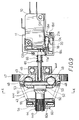
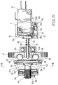
- Clutch means 43 is provided in the front lower region of the tool housing 32 between the driving gear 36 and the driven gear 42. As shown in FIGS. 7, 8, 9 and 11, the clutch means 43 includes a clutch shaft 44, a fixed clutch disc 47, two clutch balls 48, an elongated slot 50, a movable clutch disc 51, a clutch pin 52, a spring bearing member 54, and a coil spring 55.
- the clutch shaft 44 is rotatably supported in the tool housing 32 through bearings 45 and 46 and extends in parallel to the output shaft 35.
- the clutch shaft 44 has a hollow shaft portion 44a at one end thereof, a splined portion 44b at the other end thereof, and an enlarged-diameter portion 44c substantially at the intermediate portion thereof.
- the fixed clutch disc 47 is secured to the hollow shaft portion 44a of the clutch shaft 44 and has peripheral teeth normally meshed with the driving gear 36 of the output shaft 35.
- the splined portion 44b of the clutch shaft 44 is normally meshed with the driven gear 42 (FIG. 7).
- the clutch balls 48 are partially received with play within two opposite recesses 49 formed in an end face of the fixed clutch disc 47.
- the slot 50 is formed diametrically through the enlarged-diameter portion 44c of the clutch shaft 44 and extends a predetermined distance axially of the enlarged-diameter portion 44c.
- the movable clutch disc 51 is formed in a dish-like configuration and is axially movably fitted on the outer periphery of the enlarged-diameter portion 44c of the clutch shaft 44.
- the clutch pin 52 is loosely fitted in the slot 50 and has both ends engaged in two opposite cutouts 53 formed in an inclined face of the movable clutch disc 51 facing the clutch balls 48.
- the spring bearing member 54 is composed of two discs with a thrust bearing interposed therebetween and is axially movably fitted on the outer periphery of the rear end of the splined portion 44b of the clutch shaft 44.
- the coil spring 55 is disposed in compression between the spring bearing member 54 and the movable clutch disc 51 and is adapted for normally urging the movable clutch disc 51 so as to engage the clutch pin 52 with the clutch balls 48.
- a torque transmitting mechanism is constructed by the output shaft 35 of the electric motor 34, the driving gear 36, the clutch means 43, the driven gear 42, the spindle 37 and other components.
- adjusting means 56 is provided in the front lower region of the tool housing 32 to adjust the biasing force of the clutch means 43.
- the adjusting means 56 includes an adjusting knob 57, an adjusting shaft 58, an adjusting plate 59, and an L-shaped abutting member 60.
- the adjusting shaft 58 is rotatably supported in the tool housing 32 and has one end projecting out of the tool housing 32 for carrying the adjusting knob 57 and the other end facing the splined portion 44b of the clutch shaft 44.
- the adjusting plate 59 is eccentrically attached to the other end of the adjusting shaft 58 and has a peripheral cam face so formed as to steppingly change the distance from the axis of the adjusting shaft 58.
- the L-shaped abutting member 60 has a shorter leg 60a inserted in abutment between the outer periphery of the adjusting plate 59 and the end face of the spring bearing member 54 and has forked longer legs 60b (only one of which is shown in FIG.
- the adjusting knob 57 has on the back side thereof a plurality of recesses 61 (two of which are shown in FIG. 7) circumferentially arranged at positions corresponding to respective adjusting steps of the adjusting plate 59.
- the tool housing 32 is provided at a position opposite to one of the recesses 61 with a locking ball 62 urged by a spring 63 to project outwardly thereof, so that a portion of the locking ball 62 may be engaged in the recess 61 to lock the adjusting knob 57 and the adjusting shaft 58 against rotation relative to the tool housing 32.
- the holder 11 for the micro switch 10 is mounted in the boundary between the tool housing 32 and the handle housing 33, and has mounted thereon the combined locking mechanism and switch illustrated in FIGS. 1 to 5.
- the operating lever 21 is pivotally supported at the lower end thereof by the pin 22 and is adapted to operate the micro switch 10.
- the operating lever 21 is normally urged by a compression coil spring 64 in the counterclockwise direction (as viewed in FIG. 7) or the direction opposite to depression.
- the upper portion of the operating lever 21 is loosely inserted into the guide hole 20 formed in the holder 11.
- the operating lever 21 is also provided at the upper end thereof with the operating tongue 21a projecting inwardly to be engaged against the outside face of the actuating member 18.
- the operating tongue 21a is normally in abutment against the medial portion 18a and the rear end portion 18c of the actuating member 18 and in this condition, the actuator 17 of the micro switch 10 is off (FIG. 8).
- the operating lever 21 is depressed and moved pivotally, the operating tongue 21a is moved from the medial portion 18a through the L-shaped portion 18d of the actuating member 18 to the upper right (as viewed in FIG. 8), causing inward movement of the actuating member 18.
- the free end portion 13c of the leaf spring 13 is inwardly displaced against the spring force thereof, so that the actuator 17 of the micro switch 10 is displaced to the on condition (FIG. 9).
- the actuating shaft 16 has a length portion extending from substantially the medial portion to the front end and inserted in the hollow shaft portion 44a of the clutch shaft 44, with the front end held in abutment against the clutch pin 52 of the clutch means 43, and the rear end loosely inserted through the elongated guide slot 15 formed in the support piece 11a of the holder 11.
- the actuating shaft 16 is provided at the rear end thereof with the enlarged-diameter end portion 16a which is inserted through the mounting hole 14 of the leaf spring 13 to be engaged therewith.
- the actuating shaft 16 is also formed substantially at the medial portion thereof with a flange 65.
- a coil spring 66 is positioned between the flange 65 and the support piece 11a of the holder 11 so as to normally urge the front end of the actuating shaft 16 against the clutch pin 52.
- a change-over switch 67 is provided in the front upper portion of the tool housing 32 and is accessible from outside for changing the rotation of the electric motor 34 in either forward or reverse direction.
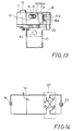
- FIG. 14 shows a power-supply circuit in which the electric motor 34 is connected to a power source W.
- the power-supply circuit includes the micro switch 10 and the change-over switch 67 connected between the micro switch 10 and the electric motor 34 for changing the polarity of the electric motor 34.
- the change-over switch 67 When it is desired to fasten a screw, the change-over switch 67 is initially connected as shown in the solid lines in FIG. 14 for forward rotation.
- the operating lever 21 is then depressed to thereby turn on the micro switch 10 (FIG. 9), as discussed previously with reference to FIGS. 1 and 4.
- the rotation of the electric motor 34 is transmitted from the driving gear 36 and the fixed clutch disc 47 through engagement between the clutch balls 48 and the clutch pin 52 of the movable clutch disc 51 to the clutch shaft 44, causing the clutch shaft 44 to rotate.
- the rotation of the clutch shaft 44 is then transmitted through the splined portion 44b of the clutch shaft 44 and the driven gear 42 engaged therewith to the spindle 37 to rotate the same in the forward direction, so that a screw can be fastened by the driver bit 41.
- the micro switch 10 When the micro switch 10 is turned off and power supply to the electric motor 34 is shut off, the micro switch 10 is simultaneously connected to the contact b to form a short circuit (see FIG. 14) which constitutes a dynamic braking circuit for the electric motor 34, with the power source W disconnected, for applying a braking force to the electric motor 34 to prevent inertial rotation of the output shaft 35. This avoids application of excessive torque to the fastened screw.
- the fastening torque can be controlled by adjusting the biasing force of the coil spring 55 of the clutch means 43.
- the adjusting shaft 58 of the adjusting means 56 is rotated by the adjusting knob 57 to change the abutting position of the adjusting plate 59 against the abutting member 60 and consequently to displace the spring bearing member 54 axially of the clutch shaft 44.
- the biasing force of the coil spring 55 in the clutch means 43 can be adjusted.
- the change-over switch 67 is set to the reverse rotation position to make the connection as shown in the dotted lines of FIG. 14, and then, when the operating lever 21 is depressed, the micro switch 10 is turned on in the manner as described above, while the electric motor 34 is rotated in the reverse direction in contrast with the above mentioned case where the screw is to be fastened. If the screw has been firmly fastened, the clutch means 43 is disengaged in the same manner as described above in connection with the forward rotation to shut off transmission of rotation from the output shaft 35 to the spindle 37. Simultaneously therewith, the actuating shaft 16 operatively associated with the clutch means 43 and the combined locking mechanism and switch moves as described above to turn off the micro switch 10.
- the adjusting knob 57 of the adjusting means 56 is controlled to set the biasing force of the coil spring 55 of the clutch means 43 to such a level that the clutch means 43 may be disengaged at the torque stronger than that for fastening. Therefore, with the clutch means 43 thus held in its engaging condition, the micro switch 10 can be held on to continuously drive the electric motor 34 for reverse rotation.
- the reverse rotation is transmitted, in the same manner as described above in connection with the forward rotation, from the drive gear 36 and the fixed clutch disc 47 through engagement between the clutch balls 48 and the clutch pin 52 of the movable clutch disc 51 to the clutch shaft 44, causing the clutch shaft 44 to rotate in the reverse direction.
- the rotation of the clutch shaft 44 is then transmitted through the splined portion 44b of the clutch shaft 44 and the driven gear 42 engaged therewith to the spindle 37 to rotate the same in the reverse direction, so that the screw can be loosened.
- a snap-type micro switch 110 is secured to a holder 111 by a bolt 112.
- the holder 111 includes a base portion 113, a switch mounting arm 114, a slide guide 115, a spring bearing member 116, an operating lever mounting arm 117.
- the micro switch 110 has a pair of mounting holes 118 and 120, and the switch mounting arm 114 has a tapped hole 119 and a through hole 121 formed with a boss 122.
- the bolt 112 is inserted into the mounting hole 118 of the micro switch 110 and screwed into the tapped hole 119.
- the boss 122 is inserted into the mounting hole 120 for positioning the switch mounting arm 114.
- the slide guide 115 includes upper and lower outer guide pieces 123 and 124 and a central inner guide piece 125 rising and then extending in parallel to the outer guide pieces 123 and 124.
- a slide piece 126 is provided and has an elongated hole 127 through which the central inner guide piece 125 is inserted, so that the slide piece 126 may be held between the outer guide pieces 123 and 124 and the inner guide piece 125.
- projecting pieces may be formed, extending from the top of the guide piece 123 and the bottom of the guide piece 124 and bent inwardly so as to guide or receive the slide piece 126 therebetween.
- the slide piece 126 may be formed at the top and the bottom thereof with ridges to guide or receive the guide piece 125 therebetween.
- the slide piece 126 is a U-shaped member having both ends 128 and 129 inwardly bent substantially at right angles.
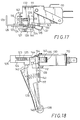
- An L-shaped leaf spring 130 serving as a linking member is secured at the base end thereof by a pin 131 to the outside of one end 128 of the slide piece 126 adjacent to the micro switch 110 (FIGS. 15 and 17).
- the pin 131 extends from the inside of the end 128, serving as a guide pin for a compression coil spring 132 positioned between the end 128 and the spring bearing member 116 of the holder 111.
- the other end 129 of the slide piece 126 is of a forked configuration to be connected with an actuating shaft (not shown), so that when the torque exceeds a predetermined level, the slide piece 126 may be drawn through the actuating shaft.
- the holder 111 is integrally formed between the slide guide 115 and the operating lever mounting arm 117 with an operating lever guide piece 133 bent and directed downwardly.
- the operating lever guide piece 133 has a flat upper face from which a pin 134 extends upwardly to pivotally movably support an actuating member 135.
- An E-ring 136 is fitted to prevent falling off of the actuating member 135 from the pin 134.
- the actuating member 135 has a front end portion and a rear end portion extending downwardly (as seen in FIG. 17) from the pivot point.
- the front end portion is inwardly bent substantially at right angles, and the rear end portion has a distal end 137 disposed in opposed relation to the distal end of the leaf spring 130.
- the operating lever mounting arm 117 is formed at the lower end thereof with a cylindrically rounded bearing portion 138 through which an operating member or lever 139 is pivotally movably supported by a pin 140.
- a compression coil spring 141 is positioned between the mounting arm 117 and the operating lever 139 at the respective intermediate positions so as to urge the operating lever 139 in a direction away from the mounting arm 117.
- the urging force is limited by abutment of the upper portion of the operating lever 139 against a stopper piece 142 formed by bending a portion of the holder 111 (FIGS. 17 and 18).
- the operating lever 139 is formed at the upper portion thereof with a guide groove 143 in which the operating lever guide piece 133 is fitted so that the swinging movement of the operating lever 139 may be guided.
- the operating lever 139 has an operating piece 144 formed in the inside of the upper portion thereof and adapted to be slidingly moved in engagement with the back side of the actuating member 135.
- the leaf spring 130 is urged by the coil spring 132 toward the micro switch 110, so that it is located over and in opposing relation to an actuator 145 of the micro switch 110, with the distal end of the leaf spring 130 disposed in opposing relation to the distal end 137 of the actuating member 135.
- This condition in which the slide piece 126 is urged by the coil spring 132 toward the micro switch 110 and the leaf spring 130 is in a first position opposing to the distal end 137 of the actuating member 135 is the normal condition of the combined locking mechanism and switch.
- the linking member may be any suitable member other than the leaf spring 130, and the means for displacing the leaf spring 130 from the first position to the second position may be any suitable means such as a linkage other than the slide piece 126.
- the operating lever 139 serving as the operating member may be replaced by an operating push button.
- the actuating member 135 may be omitted, so that the operating member may directly press the actuator through the linking member.
- various types of actuators are suitable for the micro switch.
- the combined locking mechanism and switch of the second embodiment can be mounted on the power tool by the same structure as described in connection with the first embodiment.
Landscapes
- Engineering & Computer Science (AREA)
- Mechanical Engineering (AREA)
- Details Of Spanners, Wrenches, And Screw Drivers And Accessories (AREA)
Claims (9)
- Schaltvorrichtung, umfassend:
ein von einer Bedienungsperson betätigbares Betätigungsglied (21, 139); und
einen Schalter (10, 110) mit einem Aktuator (17, 145), derart ausgestaltet, daß, wenn sich der Aktuator (17, 145) in der Ein-Position befindet, Strom durch den Schalter fließen kann, während dam, wenn sich der Aktuator (17, 145) in der Aus-Position befindet, kein Strom durch den Schalter fließen kann;
dadurch gekennzeichnet, daß die Vorrichtung weiterhin aufweist:
ein Stellglied (18; 135); und
ein Bindeglied (13, 130), welches so angeordnet ist, daß es sich normalerweise in Bezug auf das Stellglied (18, 135) in einer ersten Position befindet, in welcher ersten Position das Bindeglied (13, 130) sich in einem Bewegungspfad des Aktuators (17, 145) befindet, wobei das Bindeglied (13, 130) in eine zweite Position relativ zu dem Stellglied (18, 135) verschiebbar ist, in welcher das Bindeglied (13, 130) sich außerhalb des Bewegungspfads des Aktuators (17, 145) befindet;
wobei das Stellglied (18, 135) sich in Gegenüberstellung bezüglich des Aktuators (17, 145) mit dem dazwischen angeordneten Bindeglied (13, 130) befindet, so daß, wenn das Bindeglied (13, 130) sich in der ersten Position befindet, das Stellglied (18, 135) durch Betätigung des Betätigungsglieds (21, 139) bewegbar ist, um den Aktuator (17, 145) über das Bindeglied (13, 130) in seine Ein-Position zu verschieben, während dann, wenn das Bindeglied (13, 130) in die zweite Position verschoben ist, das Bindeglied (13, 130) von dem Aktuator (17, 145) gelöst ist, wodurch der Aktuator sich in seine Aus-Position bewegt. - Vorrichtung nach Anspruch 1, bei der das Stellglied (18, 135) schwenkbar und bewegbar durch ein innerhalb des Mechanismus bewegliches Betätigungsglied (21, 139) ist.
- Vorrichtung nach Anspruch 1 oder 2, umfassend:
einen Träger (11)zur Aufnahme des Schalters (10); wobei
das Betätigungsglied (21) verschieblich und in der Lage ist, ein fernes Ende (18e) des Stellglieds (18) mit Druck zu beaufschlagen;
das Bindeglied (13) einen an dem Schalter und/oder dem Träger fixierten Basisabschnitt (13a) aufweist, weiterhin einen freien Endabschnitt (13d), der sich in Gegenüberstellung zu dem Aktuator (17) befindet, und eine Mittelabschnitt (13b) mit dem ein Überlastungsfühlglied (16) verbunden ist; und
das Stellglied schwenkbar an dem Träger gelagert ist und das ferne Ende (18e) normalerweise in Gegenüberstellung zu dem freien Endabschnitt des Bindeglieds liegt, und das ferne Ende des Stellglieds sich von dem freien Endabschnitt des Bindeglieds löst, wenn das Bindeglied durch die Vorspannkraft einer Schraubenfeder (66) bewegt wird. - Vorrichtung nach Anspruch 1 oder 2, gekennzeichnet durch:
einen Träger (111) zum Aufnehmen des Schalters (110);
ein Gleitstück (126), welches verschieblich an dem Träger befestigt ist;
wobei das Bindeglied ein Plattenglied (130) aufweist, welches an dem Gleitstück (126) derart befestigt ist, daß es sich in Gegenüberstellung zu dem Aktuator (145) befindet;
eine Schraubenfeder (132), welche das Gleitstück in Richtung auf den Schalter drängt;
ein Stellglied (135), welches verschwenkbar an dem Träger gelagert ist und ein freies Ende (137) aufweist, welches sich normalerweise in Gegenüberstellung zu dem Plattenglied befindet, wobei das ferne Ende des Stellglieds von dem Plattenglied gelöst ist, wenn das Gleitstück gegen die Vorspannkraft der Schraubenfeder gezogen wird; und
ein Betätigungsglied (139) zum Drücken des fernen Endes des Stellglieds. - Vorrichtung nach Anspruch 1, bei der das Stellglied (18) einen im wesentlichen L-förmigen Endabschnitt (18d) aufweist, der in Richtung auf den Aktuator (17) beweglich ist, wenn das Betätigungsglied (21) betätigt wird, wobei das Bindeglied (13) die Form eines Metallblechs aufweist, welches sich in Gegenüberstellung zu dem Aktuator (17) befindet, wobei das Bindeglied (13) gegen den L-förmigen Endabschnitt (18d) des Stellglieds (18) anschlägt, wenn sich das Bindeglied (13) in der ersten Stellung befindet, während das Bindeglied von dem L-förmigen Endabschnitt (18d) des Stellglieds (18) beabstandet ist, wenn sich das Bindeglied (13) in der zweiten Position befindet.
- Motorgetriebenes Werkzeug, umfassend:
ein Werkzeuggehäuse (32);
einen in dem Werkzeuggehäuse (32) eingeschlossenen Elektromotor (34);
ein aus dem Werkzeuggehäuse (32) vorstehendes Einspannfutter (40);
einen Drehmomentübertragungsmechanismus (36-39, 44-45)zum Übertragen eines Drehmoments von dem Elektromotor (34) auf das Einspannfutter (40);
eine Schaltvorrichtung gemäß Anspruch 1, 2, 3, 4 oder 5, wobei das Betätigungsglied (21, 139) an dem Werkzeuggehäuse (32) angebracht und der Schalter (10, 110) mit dem Elektromotor (34) verbunden ist;
ein Überlastungsfühlglied (16), welches mechanisch mit dem Drehmomentübertragungsmechanismus (36, 43, 43) verbunden ist und verschiebbar ist, wenn ein ein vorbestimmtes Niveau übersteigendes Drehmoment zwischen dem Elektromotor (34) und dem Einspannfutter (40) erzeugt wird; wobei das Überlastungsfühlglied das Bindeglied (13, 130) in dessen zweite Position verschiebt, wenn ein oberhalb des vorbestimmten Niveaus liegendes Drehmoment erzeugt wird. - Werkzeug nach Anspruch 6, bei dem der Drehmomentübertragungsmechanismus (36-39, 44-55) eine Kupplungseinrichtung (44-55) aufweist, die ein erstes Kupplungsglied (51), welches relativ zu dem Werkzeuggehäuse (32) bewegbar ist, und ein zweites Kupplungsglied (47), welches relativ zu dem Werkzeuggehäuse (32) fixiert ist, aufweist, wobei das erste und das zweite Kupplungsglied voneinander weg bewegt werden, wenn ein oberhalb eines vorbestimmten Niveaus liegendes Drehmoment übertragen wird, und wobei das Überlastungsfühlglied (16) mechanisch mit dem ersten Kupplungsglied verbunden ist.
- Werkzeug nach Anspruch 6 oder 7, bei dem das Stellglied (18) einen im wesentlichen L-förmigen Endabschnitt (18d) aufweist, wobei das Bindeglied (13) eine im wesentlichen L-förmigen Blattfeder ist, die mit einer Seite mechanisch an das Überlastungsfühlglied (16) gekoppelt ist, das Bindeglied einen freien Endabschnitt (13d) aufweist, der in der Lage ist, an dem fernen Ende (18e) des L-förmigen Endabschnitts des Stellglieds zur Anlage zu kommen, wenn das Bindeglied sich in seiner ersten Position befindet, und das Bindeglied durch Verlagerung des Überlastungsfühlglieds elastisch durchgebogen wird, mit der Folge, daß das ferne Ende des freien Endabschnitts von ihm in Kontakt mit der Innenseite der Ecke des L-förmigen Endabschnitts des Stellglieds gelangt.
- Vorrichtung nach Anspruch 6 oder 7, bei der das Stellglied (18) einen im wesentlichen L-förmigen Endabschnitt (18d) aufweist, wobei das Bindeglied (13) die Form eines Metallblechs besitzt, das Bindeglied einen Teil (13b) besitzt, der mechanisch mit dem Überlastungsfühlglied (16) gekoppelt ist, und ein Ende (13d) besitzt, welches im Stande ist, an dem fernen Ende (18e) des L-förmigen Endabschnitts (18d) des Stellglieds (18) zur Anlage zu kommen, wenn das Bindeglied (13) sich in der ersten Stellung befindet, wobei das Bindeglied verschieblich ist, wenn das Überlastungsfühlglied versetzt wird, was zur Folge hat, daß das Ende (13d) von dem fernen Ende des L-förmigen Endabschnitts loskommt.
Applications Claiming Priority (8)
| Application Number | Priority Date | Filing Date | Title |
|---|---|---|---|
| JP7720888A JPH0773018B2 (ja) | 1988-03-30 | 1988-03-30 | ロツクスイツチ |
| JP7720988A JPH0773019B2 (ja) | 1988-03-30 | 1988-03-30 | ロツクスイツチ |
| JP77209/88 | 1988-03-30 | ||
| JP77207/88 | 1988-03-30 | ||
| JP77017/88 | 1988-03-30 | ||
| JP77208/88 | 1988-03-30 | ||
| JP63077207A JPH07123014B2 (ja) | 1988-03-30 | 1988-03-30 | 電動工具用ロックスイッチ |
| JP63077017A JP2618428B2 (ja) | 1988-03-30 | 1988-03-30 | 電動工具の回転制御装置 |
Publications (3)
| Publication Number | Publication Date |
|---|---|
| EP0335700A2 EP0335700A2 (de) | 1989-10-04 |
| EP0335700A3 EP0335700A3 (en) | 1990-10-24 |
| EP0335700B1 true EP0335700B1 (de) | 1994-07-27 |
Family
ID=27465993
Family Applications (1)
| Application Number | Title | Priority Date | Filing Date |
|---|---|---|---|
| EP89303121A Expired - Lifetime EP0335700B1 (de) | 1988-03-30 | 1989-03-30 | Kombination von Schalter und Sperrvorrichtung |
Country Status (3)
| Country | Link |
|---|---|
| US (1) | US4934494A (de) |
| EP (1) | EP0335700B1 (de) |
| DE (1) | DE68916993T2 (de) |
Families Citing this family (14)
| Publication number | Priority date | Publication date | Assignee | Title |
|---|---|---|---|---|
| JP3291609B2 (ja) * | 1996-02-13 | 2002-06-10 | 株式会社マキタ | 電動工具のクラッチ機構 |
| US5638945A (en) * | 1996-06-10 | 1997-06-17 | Ryobi North America, Inc. | Locking trigger mechanism for a portable power tool |
| US5941851A (en) * | 1996-07-12 | 1999-08-24 | C.R. Bard, Inc. | Pulsed lavage handpiece with improved handle |
| US6392374B1 (en) * | 1998-02-10 | 2002-05-21 | Somfy | Device for control of an electric motor driving a moving object |
| US6012622A (en) | 1998-04-20 | 2000-01-11 | Illinois Tool Works Inc. | Fastener driving tool for trim applications |
| US6057518A (en) | 1998-08-14 | 2000-05-02 | Black & Decker, Inc. | Lockout mechanism for power tool |
| US6091035A (en) | 1998-08-14 | 2000-07-18 | Black & Decker, Inc. | Lockout mechanism for power tool |
| ATE333140T1 (de) * | 1999-11-02 | 2006-08-15 | Hans-Peter Loeffler | Kraftschlussdetektor mit drehmomentschalter |
| DE102004051913A1 (de) * | 2004-08-09 | 2006-02-23 | Robert Bosch Gmbh | Akkuschrauber |
| US6958455B1 (en) * | 2004-09-16 | 2005-10-25 | Defond Components Limited | Lock-on/lock-off tool switch |
| EP2714339B1 (de) | 2011-06-02 | 2018-01-03 | Black & Decker Inc. | Steuersystem für ein elektrisches befestigungswerkzeug |
| US8872049B2 (en) | 2012-04-18 | 2014-10-28 | Milwaukee Electric Tool Corporation | Trigger lock-on lock-off mechanism |
| US10043619B2 (en) | 2014-03-28 | 2018-08-07 | Black & Decker Inc. | Biasing member for a power tool forward/reverse actuator |
| US10541588B2 (en) | 2017-05-24 | 2020-01-21 | Black & Decker Inc. | Electronic power module for a power tool having an integrated heat sink |
Family Cites Families (10)
| Publication number | Priority date | Publication date | Assignee | Title |
|---|---|---|---|---|
| US2052152A (en) * | 1932-05-19 | 1936-08-25 | Arthur B Webb | Torque transmission mechanism |
| US2717672A (en) * | 1951-01-26 | 1955-09-13 | Chicago Pneumatic Tool Co | Impact wrench torque control |
| DE1159867B (de) * | 1959-06-20 | 1963-12-19 | Fein C & E | Schlagschrauber mit drehmomentabhaengiger Abschaltung des insbesondere elektromotorischen Antriebs |
| US3786286A (en) * | 1972-09-14 | 1974-01-15 | Isabergs Verkstads Ab | Self-interrupting reciprocating motor |
| US4265320A (en) * | 1977-05-16 | 1981-05-05 | Matsushita Electric Industrial Co., Ltd. | Electrically powered torque-controlled tool |
| EP0086244B1 (de) * | 1982-02-13 | 1985-01-16 | Joh. Friedrich Behrens AG | Auslösesicherung für ein kraftgetriebenes Eintreibgerät |
| JPS6020870A (ja) * | 1983-07-12 | 1985-02-02 | 日立工機株式会社 | クラツチ式電動締付工具の制御方式 |
| US4756216A (en) * | 1986-07-02 | 1988-07-12 | Top Driver Enterprise Co., Ltd. | Turn-on and turn-off control apparatus for electric screw-drivers |
| US4712456A (en) * | 1986-07-02 | 1987-12-15 | Top Driver Enterprise Co., Ltd. | Electric torsion-controlled screwdriver with an improved automatic turn-off device |
| SE461510B (sv) * | 1986-11-27 | 1990-02-26 | Atlas Copco Ab | Aktiveringsarrangemang vid elektrisk skruvdragare |
-
1989
- 1989-03-24 US US07/328,324 patent/US4934494A/en not_active Expired - Lifetime
- 1989-03-30 DE DE68916993T patent/DE68916993T2/de not_active Expired - Fee Related
- 1989-03-30 EP EP89303121A patent/EP0335700B1/de not_active Expired - Lifetime
Also Published As
| Publication number | Publication date |
|---|---|
| EP0335700A2 (de) | 1989-10-04 |
| DE68916993T2 (de) | 1995-03-16 |
| EP0335700A3 (en) | 1990-10-24 |
| US4934494A (en) | 1990-06-19 |
| DE68916993D1 (de) | 1994-09-01 |
Similar Documents
| Publication | Publication Date | Title |
|---|---|---|
| US4934494A (en) | Combined locking mechanism and switch especially for power tools | |
| US5339908A (en) | Power tool | |
| EP1129826B1 (de) | Elektrisches Handwerkzeug | |
| EP0623427B1 (de) | Kraftwerkzeuge und Schlagmechanismus dafür | |
| US5361853A (en) | Power tool | |
| US7607493B2 (en) | Hand-held electric power tool | |
| US5277527A (en) | Torque adjustment device | |
| US4204580A (en) | Forward biased switch for a reversible hammer drill | |
| EP0351179A1 (de) | Vorrichtung zur Einstellung des Drehmoments für kraftbetriebene rotierende Werkzeuge | |
| JP4729159B2 (ja) | 手持ち式の電動複合ハンマ装置 | |
| US5568849A (en) | Clutch mechanism in power driven screwdriver | |
| US7856724B2 (en) | Electrical power tool with a rotatable working tool | |
| US20030173178A1 (en) | Torque transmission mechanisms and power tools having such torque transmission mechanisms | |
| JPH0539814U (ja) | 回転電動工具の動力伝達機構 | |
| CN101143440A (zh) | 电动工具 | |
| JP5351555B2 (ja) | 電動工具のスイッチ | |
| JPH06262414A (ja) | 電動工具 | |
| JP3086991B2 (ja) | 電動工具のスイッチ機構 | |
| JP3391855B2 (ja) | 回転工具の回転制御装置 | |
| JPH07194885A (ja) | ミシンの駆動装置 | |
| JPH01252369A (ja) | 電動工具の回転制御装置 | |
| JPH06262539A (ja) | トルク感応型可変クラッチ付インパクト式回転工具 | |
| JPH071355A (ja) | トルク感応型可変クラッチ付回転工具 | |
| JPH0346445Y2 (de) | ||
| JPH01248417A (ja) | 電動工具用ロックスイッチ |
Legal Events
| Date | Code | Title | Description |
|---|---|---|---|
| PUAI | Public reference made under article 153(3) epc to a published international application that has entered the european phase |
Free format text: ORIGINAL CODE: 0009012 |
|
| AK | Designated contracting states |
Kind code of ref document: A2 Designated state(s): DE FR GB NL |
|
| PUAL | Search report despatched |
Free format text: ORIGINAL CODE: 0009013 |
|
| AK | Designated contracting states |
Kind code of ref document: A3 Designated state(s): DE FR GB NL |
|
| 17P | Request for examination filed |
Effective date: 19901214 |
|
| 17Q | First examination report despatched |
Effective date: 19930319 |
|
| GRAA | (expected) grant |
Free format text: ORIGINAL CODE: 0009210 |
|
| AK | Designated contracting states |
Kind code of ref document: B1 Designated state(s): DE FR GB NL |
|
| REF | Corresponds to: |
Ref document number: 68916993 Country of ref document: DE Date of ref document: 19940901 |
|
| ET | Fr: translation filed | ||
| PLBE | No opposition filed within time limit |
Free format text: ORIGINAL CODE: 0009261 |
|
| STAA | Information on the status of an ep patent application or granted ep patent |
Free format text: STATUS: NO OPPOSITION FILED WITHIN TIME LIMIT |
|
| 26N | No opposition filed | ||
| REG | Reference to a national code |
Ref country code: GB Ref legal event code: IF02 |
|
| PGFP | Annual fee paid to national office [announced via postgrant information from national office to epo] |
Ref country code: NL Payment date: 20070304 Year of fee payment: 19 |
|
| PGFP | Annual fee paid to national office [announced via postgrant information from national office to epo] |
Ref country code: DE Payment date: 20070322 Year of fee payment: 19 |
|
| PGFP | Annual fee paid to national office [announced via postgrant information from national office to epo] |
Ref country code: GB Payment date: 20070328 Year of fee payment: 19 |
|
| PGFP | Annual fee paid to national office [announced via postgrant information from national office to epo] |
Ref country code: FR Payment date: 20070308 Year of fee payment: 19 |
|
| GBPC | Gb: european patent ceased through non-payment of renewal fee |
Effective date: 20080330 |
|
| PG25 | Lapsed in a contracting state [announced via postgrant information from national office to epo] |
Ref country code: NL Free format text: LAPSE BECAUSE OF NON-PAYMENT OF DUE FEES Effective date: 20081001 |
|
| NLV4 | Nl: lapsed or anulled due to non-payment of the annual fee |
Effective date: 20081001 |
|
| REG | Reference to a national code |
Ref country code: FR Ref legal event code: ST Effective date: 20081125 |
|
| PG25 | Lapsed in a contracting state [announced via postgrant information from national office to epo] |
Ref country code: DE Free format text: LAPSE BECAUSE OF NON-PAYMENT OF DUE FEES Effective date: 20081001 |
|
| PG25 | Lapsed in a contracting state [announced via postgrant information from national office to epo] |
Ref country code: FR Free format text: LAPSE BECAUSE OF NON-PAYMENT OF DUE FEES Effective date: 20080331 |
|
| PG25 | Lapsed in a contracting state [announced via postgrant information from national office to epo] |
Ref country code: GB Free format text: LAPSE BECAUSE OF NON-PAYMENT OF DUE FEES Effective date: 20080330 |