EP0335440B1 - Device for grinding a bearing journal of the crankshaft of a combustion engine, in particular a diesel engine - Google Patents
Device for grinding a bearing journal of the crankshaft of a combustion engine, in particular a diesel engine Download PDFInfo
- Publication number
- EP0335440B1 EP0335440B1 EP89200704A EP89200704A EP0335440B1 EP 0335440 B1 EP0335440 B1 EP 0335440B1 EP 89200704 A EP89200704 A EP 89200704A EP 89200704 A EP89200704 A EP 89200704A EP 0335440 B1 EP0335440 B1 EP 0335440B1
- Authority
- EP
- European Patent Office
- Prior art keywords
- grinding
- journal
- axis
- imaginary
- upright elements
- Prior art date
- Legal status (The legal status is an assumption and is not a legal conclusion. Google has not performed a legal analysis and makes no representation as to the accuracy of the status listed.)
- Expired - Lifetime
Links
- 238000002485 combustion reaction Methods 0.000 title claims abstract description 4
- 238000000034 method Methods 0.000 claims description 7
- 230000004323 axial length Effects 0.000 claims description 3
- XAGFODPZIPBFFR-UHFFFAOYSA-N aluminium Chemical compound [Al] XAGFODPZIPBFFR-UHFFFAOYSA-N 0.000 description 1
- 229910052782 aluminium Inorganic materials 0.000 description 1
- 239000004411 aluminium Substances 0.000 description 1
- 230000000694 effects Effects 0.000 description 1
- 230000001050 lubricating effect Effects 0.000 description 1
Images


Classifications
-
- B—PERFORMING OPERATIONS; TRANSPORTING
- B24—GRINDING; POLISHING
- B24B—MACHINES, DEVICES, OR PROCESSES FOR GRINDING OR POLISHING; DRESSING OR CONDITIONING OF ABRADING SURFACES; FEEDING OF GRINDING, POLISHING, OR LAPPING AGENTS
- B24B5/00—Machines or devices designed for grinding surfaces of revolution on work, including those which also grind adjacent plane surfaces; Accessories therefor
- B24B5/36—Single-purpose machines or devices
- B24B5/42—Single-purpose machines or devices for grinding crankshafts or crankpins
-
- B—PERFORMING OPERATIONS; TRANSPORTING
- B24—GRINDING; POLISHING
- B24B—MACHINES, DEVICES, OR PROCESSES FOR GRINDING OR POLISHING; DRESSING OR CONDITIONING OF ABRADING SURFACES; FEEDING OF GRINDING, POLISHING, OR LAPPING AGENTS
- B24B21/00—Machines or devices using grinding or polishing belts; Accessories therefor
- B24B21/02—Machines or devices using grinding or polishing belts; Accessories therefor for grinding rotationally symmetrical surfaces
-
- F—MECHANICAL ENGINEERING; LIGHTING; HEATING; WEAPONS; BLASTING
- F02—COMBUSTION ENGINES; HOT-GAS OR COMBUSTION-PRODUCT ENGINE PLANTS
- F02B—INTERNAL-COMBUSTION PISTON ENGINES; COMBUSTION ENGINES IN GENERAL
- F02B3/00—Engines characterised by air compression and subsequent fuel addition
- F02B3/06—Engines characterised by air compression and subsequent fuel addition with compression ignition
Definitions
- the invention relates to a method for grinding a bearing journal of the crankshaft of a combustion engine, in particular a diesel engine without removing it from the engine.
- a hand operated device for grinding a bearing journal of the crankshaft of e.g. a diesel engine which device comprises a support provided with handles and in which two rollers are journaled of which one roller is driven, over which an endless grinding belt is passed. Between said rollers a pressure member is removably connected to said support, said member having a concave groove at its lower pressure surface, said groove having a curvature which corresponds with the curvature of the journal to be treated. Further guiding elements are provided on both sides of the pressure member which bear against the surface of the journal to be treated at points which are situated on two spaced apart lines extending parallel to the axis of the journal to be treated.
- the object of the invention is to provide a method of the type mentioned above, by which the crankshaft of even today's engines with thin bearing shells can be treated in the engine as regards grinding one or more of its bearing journals.
- a device comprises a support having mounted thereon two upright elements which extend essentially along two parallel planes spaced apart, and which are provided at their top ends with a circular arc-shaped, concave guide edge in such a way that the imaginary straight line through the centre points of the two circular arcs is perpendicular to the two upright elements and forms the axis of an imaginary cylindrical surface, the diameter of each circular arc being essentially equal to the original diameter of the bearing journal to be treated, and the shortest distance between the guide edges being smaller than the axial length of the bearing journal to be treated, but being greater than the axial dimension of the attacked part of this journal, and the device also has at least one grinding element which is fitted below the guide edges between the upright elements, and the grinding surface of which touches the above-mentioned imaginary cylindrical surface at least along a line, is held by means which are also present with said guide edges pressed against the journal to be treated on either side of the grinding surface, the crankshaft is rotated so that the journal to be
- the invention relates also to a device for executing the method which device comprises a support having mounted thereon two upright elements which extend essentially along two parallel planes spaced apart, and which are provided at their top ends with a circular arc-shaped, concave guide edge in such a way that the imaginary straight line through the centre points of the two circular arcs is perpendicular to the two upright elements and forms the axis of an imaginary cylindrical surface, the diameter of each circular arc being equal to a predetermined diameter and the shortest distance between the guide edges having a predetermined dimension, and the device also has at least one grinding element which is fitted below the guide edges between the upright elements, and grinding surface of which touches the above-mentioned imaginary cylindrical surface at least along a line, and means to ensure that the guide edges can be held pressed against the journal to be treated on either side of the grinding surface.
- a device designed in this way does not rotate about the journal to be treated, but is put against the journal to be treated at a place where there is always sufficient space inside the engine, generally below the journal to be treated.
- the grinding element is preferably disposed adjustably in such a way between the upright elements that the grinding surface can be moved parallel to itself at least in the direction towards the imaginary axis, so that, when it is found after some time that the grinding surface of the grinding element is no longer lying sufficiently against the journal to be able to carry out its grinding action, this grinding surface can be moved slightly,
- the grinding element is disposed adjustably in an advantageous manner between the upright elements in such a way that the ends of the line along which the grinding surface essentially touches the above-mentioned cylindrical surface can be moved independently of each other towards and away from the imaginary axis, so that the grinding surface can be set accurately.
- the grinding element preferably has a rotary roller, whose axis of rotation runs essentially parallel to the above-mentioned imaginary axis, the above-mentioned adjustability being obtained through the fact that the roller is mounted on its axis of rotation, said axis being provided at both ends with an eccentric journal, said journals being in line with each other and each being accommodated in an eccentric sleeve which is rotatably connected to the upright element in question.
- the rotary roller is preferably a supporting roller for an endless grinding belt running over the roller and also being guided around at least one drive roller.
- the above-mentioned pressure means are preferably formed by a compressed gas-filled cushion under the frame. This ensures that any movements of the crankshaft which may occur during the grinding are followed.
- outward-projecting guide elements can be disposed on the upright elements, near their guide edges.
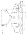
- the device comprises a frame made of a U-section 1, with a U-section 3 fastened thereto by means of strips 2.
- Two upright elements 4, 4′ in the form of plates, are mounted on either side of the U-section 3, and are held extending accurately parallel to each other by the spacing sleeves 5.
- Each plate 4, 4′ is provided at its top end with a circular arc-shaped concave recess along which a guide edge 6, 6′ of, e.g., aluminium is disposed.
- a supporting roller 10 is mounted on the shaft 7 by means of ball bearings in such a way that it rotates about the shaft 7.
- An endless grinding belt 11 runs round the supporting roller 10 and also runs around a driven roller 12 and a tensioning roller 13.
- the shaft of the tensioning roller 13 can be moved to and fro along the forks 14 by means of adjusting screws (not shown), and said forks 14 can be moved jointly relative to the frame 3 by means of the set bolt 15 with locking nut.
- Guide blocks 16, 16′ which are adjustable due to the fact that they are provided with eccentric apertures, are fitted on the outsides of the plates 4, 4′.
- the whole device is supported by an air cushion 17 when it is in operation.
- the device When the device is in operation, it is placed under the bearing journal 18 of a crankshaft 19 to be treated, and by increasing the air pressure inside the air cushion 17, the guide edges 6, 6′ are pressed against the non-attacked parts 18′ of the bearing journal 18. Since these non-attacked parts 18′, with the original diameter of the journal 18, are still absolutely round, the imaginary axis through the centre points of the circular arcs formed by the guide edges 6, 6′ will coincide with the axis of the journal bearing 18.
- crankshaft 19 is then turned slowly by means of the turning engine, for example at a speed of 3/4 r.p.m., while the motor driving the driven roller 12 is put into operation, so that the grinding belt 11 is put into rotary motion, while the part of this belt running over the supporting roller 10 has a grinding effect on the bearing journal 18.
- the shaft 7 of the supporting roller 10 is generally set in such a way that said shaft runs parallel to the above-mentioned imaginary axis, so that the journal part to be ground is ground absolutely round to a specific diameter over the entire axial length thereof. If, however, the journal 18 has a certain taper, it can be corrected by turning the sleeves 9, 9′ slightly, so that the shaft 7 can be set slightly at an angle.
- the shaft - and thus the periphery of the supporting roller - can be moved towards or away from the journal 18 to be treated, by turning the shaft 7 a little.
Landscapes
- Engineering & Computer Science (AREA)
- Mechanical Engineering (AREA)
- Shafts, Cranks, Connecting Bars, And Related Bearings (AREA)
- Grinding Of Cylindrical And Plane Surfaces (AREA)
- Grinding And Polishing Of Tertiary Curved Surfaces And Surfaces With Complex Shapes (AREA)
- Finish Polishing, Edge Sharpening, And Grinding By Specific Grinding Devices (AREA)
- Rolling Contact Bearings (AREA)
Priority Applications (1)
| Application Number | Priority Date | Filing Date | Title |
|---|---|---|---|
| AT89200704T ATE79583T1 (de) | 1988-03-29 | 1989-03-17 | Vorrichtung zum schleifen eines laserzapfens einer kurbelwelle eines verbrennungsmotors, insbesondere eines dieselmotors. |
Applications Claiming Priority (2)
| Application Number | Priority Date | Filing Date | Title |
|---|---|---|---|
| NL8800793A NL8800793A (nl) | 1988-03-29 | 1988-03-29 | Inrichting voor het slijpen van een lagertap van de krukas van een verbrandingsmotor in het bijzonder een dieselmotor. |
| NL8800793 | 1988-03-29 |
Publications (2)
| Publication Number | Publication Date |
|---|---|
| EP0335440A1 EP0335440A1 (en) | 1989-10-04 |
| EP0335440B1 true EP0335440B1 (en) | 1992-08-19 |
Family
ID=19852027
Family Applications (1)
| Application Number | Title | Priority Date | Filing Date |
|---|---|---|---|
| EP89200704A Expired - Lifetime EP0335440B1 (en) | 1988-03-29 | 1989-03-17 | Device for grinding a bearing journal of the crankshaft of a combustion engine, in particular a diesel engine |
Country Status (7)
| Country | Link |
|---|---|
| EP (1) | EP0335440B1 (https=) |
| AT (1) | ATE79583T1 (https=) |
| DE (1) | DE68902496T2 (https=) |
| ES (1) | ES2034578T3 (https=) |
| GR (1) | GR3005964T3 (https=) |
| NL (1) | NL8800793A (https=) |
| NO (1) | NO171098C (https=) |
Families Citing this family (5)
| Publication number | Priority date | Publication date | Assignee | Title |
|---|---|---|---|---|
| CA2081699C (en) * | 1992-08-14 | 1998-06-09 | James D. Phillips | Crankpin grinder |
| DE4309052A1 (de) * | 1993-03-20 | 1994-09-22 | Schaudt Maschinenbau Gmbh | Bandschleifmaschine zum Bearbeiten der Kurbelzapfen einer Kurbelwelle |
| CN109454526A (zh) * | 2018-12-26 | 2019-03-12 | 瓦房店光阳轴承股份有限公司 | 轴承外圈滚道砂带抛光装置 |
| CN113275984B (zh) * | 2021-06-02 | 2022-12-20 | 河源富马硬质合金股份有限公司 | 一种用于棒状硬质合金的外表面打磨设备 |
| CN117260482B (zh) * | 2023-11-21 | 2024-01-23 | 山西科立特精密铸造科技有限公司 | 一种曲轴同步错位抛光磨削设备 |
Family Cites Families (1)
| Publication number | Priority date | Publication date | Assignee | Title |
|---|---|---|---|---|
| CH174727A (de) * | 1933-11-21 | 1935-01-31 | Goetti Emil | Vorrichtung zum Schleifen von Zapfen, Nocken und dergleichen. |
-
1988
- 1988-03-29 NL NL8800793A patent/NL8800793A/nl not_active Application Discontinuation
-
1989
- 1989-03-17 ES ES198989200704T patent/ES2034578T3/es not_active Expired - Lifetime
- 1989-03-17 DE DE8989200704T patent/DE68902496T2/de not_active Expired - Fee Related
- 1989-03-17 AT AT89200704T patent/ATE79583T1/de not_active IP Right Cessation
- 1989-03-17 EP EP89200704A patent/EP0335440B1/en not_active Expired - Lifetime
- 1989-03-28 NO NO891296A patent/NO171098C/no unknown
-
1992
- 1992-10-12 GR GR920402287T patent/GR3005964T3/el unknown
Also Published As
| Publication number | Publication date |
|---|---|
| EP0335440A1 (en) | 1989-10-04 |
| NO891296D0 (no) | 1989-03-28 |
| NL8800793A (nl) | 1989-10-16 |
| DE68902496T2 (de) | 1993-02-18 |
| ATE79583T1 (de) | 1992-09-15 |
| ES2034578T3 (es) | 1993-04-01 |
| NO171098C (no) | 1993-01-27 |
| GR3005964T3 (https=) | 1993-06-07 |
| NO891296L (no) | 1989-10-02 |
| NO171098B (no) | 1992-10-19 |
| DE68902496D1 (de) | 1992-09-24 |
Similar Documents
| Publication | Publication Date | Title |
|---|---|---|
| RU2113578C1 (ru) | Устройство для шлифования рельсов | |
| US5992277A (en) | Apparatus for cleaning of the peripheral surface on a cylindrical part | |
| RU2245955C1 (ru) | Шлифовальный станок | |
| US5207153A (en) | Apparatus for applying printed matter to objects | |
| US5881623A (en) | Cutting carriage for sheet cutting and sheet cutter using same | |
| EP0335440B1 (en) | Device for grinding a bearing journal of the crankshaft of a combustion engine, in particular a diesel engine | |
| US6190244B1 (en) | Sharpening arrangement | |
| US5101601A (en) | Grinding workpieces | |
| CN1070777C (zh) | 用于连续运动听罐装潢机的芯轴装置的垂直轨道 | |
| US2714278A (en) | Pin chamfering machine | |
| US5219412A (en) | Method and apparatus of moving bowling-lane maintenance machine | |
| US7493788B2 (en) | Deep rolling roller head for split-pin crankshafts | |
| SU1097474A1 (ru) | Роликова опора | |
| US4372020A (en) | Slag removal apparatus | |
| GB960467A (en) | Coated abrasive belt machine | |
| SU1738611A1 (ru) | Устройство дл зачистки кромок обечаек | |
| RU2220250C2 (ru) | Устройство для шлифования профиля головки рельса | |
| NL8302272A (nl) | Draagbare inrichting voor het herstellen van cilindrische oppervlakken. | |
| SU1484631A1 (ru) | Устройство для зачистки | |
| JPS635881Y2 (https=) | ||
| JPH0866812A (ja) | 端縁加工装置 | |
| JPH08207231A (ja) | 凹版印刷機用ドクター装置 | |
| KR100923548B1 (ko) | 후판 제품 회전장치 | |
| JPS6015639Y2 (ja) | 金属板研削装置 | |
| KR20030027254A (ko) | 원형의 피가공물 표면가공기 |
Legal Events
| Date | Code | Title | Description |
|---|---|---|---|
| PUAI | Public reference made under article 153(3) epc to a published international application that has entered the european phase |
Free format text: ORIGINAL CODE: 0009012 |
|
| AK | Designated contracting states |
Kind code of ref document: A1 Designated state(s): AT BE CH DE ES FR GB GR IT LI LU NL SE |
|
| 17P | Request for examination filed |
Effective date: 19900327 |
|
| 17Q | First examination report despatched |
Effective date: 19910611 |
|
| GRAA | (expected) grant |
Free format text: ORIGINAL CODE: 0009210 |
|
| AK | Designated contracting states |
Kind code of ref document: B1 Designated state(s): AT BE CH DE ES FR GB GR IT LI LU NL SE |
|
| REF | Corresponds to: |
Ref document number: 79583 Country of ref document: AT Date of ref document: 19920915 Kind code of ref document: T |
|
| REF | Corresponds to: |
Ref document number: 68902496 Country of ref document: DE Date of ref document: 19920924 |
|
| ITF | It: translation for a ep patent filed | ||
| ET | Fr: translation filed | ||
| PGFP | Annual fee paid to national office [announced via postgrant information from national office to epo] |
Ref country code: CH Payment date: 19930325 Year of fee payment: 5 |
|
| PGFP | Annual fee paid to national office [announced via postgrant information from national office to epo] |
Ref country code: AT Payment date: 19930330 Year of fee payment: 5 |
|
| REG | Reference to a national code |
Ref country code: GR Ref legal event code: FG4A Free format text: 3005964 |
|
| REG | Reference to a national code |
Ref country code: ES Ref legal event code: FG2A Ref document number: 2034578 Country of ref document: ES Kind code of ref document: T3 |
|
| PGFP | Annual fee paid to national office [announced via postgrant information from national office to epo] |
Ref country code: LU Payment date: 19930421 Year of fee payment: 5 |
|
| PLBE | No opposition filed within time limit |
Free format text: ORIGINAL CODE: 0009261 |
|
| STAA | Information on the status of an ep patent application or granted ep patent |
Free format text: STATUS: NO OPPOSITION FILED WITHIN TIME LIMIT |
|
| 26N | No opposition filed | ||
| EPTA | Lu: last paid annual fee | ||
| PG25 | Lapsed in a contracting state [announced via postgrant information from national office to epo] |
Ref country code: LU Free format text: LAPSE BECAUSE OF NON-PAYMENT OF DUE FEES Effective date: 19940317 Ref country code: AT Effective date: 19940317 |
|
| PG25 | Lapsed in a contracting state [announced via postgrant information from national office to epo] |
Ref country code: LI Effective date: 19940331 Ref country code: CH Effective date: 19940331 |
|
| REG | Reference to a national code |
Ref country code: CH Ref legal event code: PL |
|
| PGFP | Annual fee paid to national office [announced via postgrant information from national office to epo] |
Ref country code: GR Payment date: 19950123 Year of fee payment: 7 |
|
| EAL | Se: european patent in force in sweden |
Ref document number: 89200704.8 |
|
| PGFP | Annual fee paid to national office [announced via postgrant information from national office to epo] |
Ref country code: SE Payment date: 19950315 Year of fee payment: 7 |
|
| PGFP | Annual fee paid to national office [announced via postgrant information from national office to epo] |
Ref country code: ES Payment date: 19950328 Year of fee payment: 7 |
|
| PG25 | Lapsed in a contracting state [announced via postgrant information from national office to epo] |
Ref country code: SE Effective date: 19960318 Ref country code: ES Free format text: LAPSE BECAUSE OF NON-PAYMENT OF DUE FEES Effective date: 19960318 |
|
| PG25 | Lapsed in a contracting state [announced via postgrant information from national office to epo] |
Ref country code: GR Free format text: THE PATENT HAS BEEN ANNULLED BY A DECISION OF A NATIONAL AUTHORITY Effective date: 19960930 |
|
| REG | Reference to a national code |
Ref country code: GR Ref legal event code: MM2A Free format text: 3005964 |
|
| EUG | Se: european patent has lapsed |
Ref document number: 89200704.8 |
|
| PGFP | Annual fee paid to national office [announced via postgrant information from national office to epo] |
Ref country code: NL Payment date: 19970416 Year of fee payment: 9 |
|
| PGFP | Annual fee paid to national office [announced via postgrant information from national office to epo] |
Ref country code: GB Payment date: 19970429 Year of fee payment: 9 Ref country code: BE Payment date: 19970429 Year of fee payment: 9 |
|
| PGFP | Annual fee paid to national office [announced via postgrant information from national office to epo] |
Ref country code: DE Payment date: 19970505 Year of fee payment: 9 |
|
| PGFP | Annual fee paid to national office [announced via postgrant information from national office to epo] |
Ref country code: FR Payment date: 19970513 Year of fee payment: 9 |
|
| PG25 | Lapsed in a contracting state [announced via postgrant information from national office to epo] |
Ref country code: GB Free format text: LAPSE BECAUSE OF NON-PAYMENT OF DUE FEES Effective date: 19980317 |
|
| PG25 | Lapsed in a contracting state [announced via postgrant information from national office to epo] |
Ref country code: FR Free format text: THE PATENT HAS BEEN ANNULLED BY A DECISION OF A NATIONAL AUTHORITY Effective date: 19980331 Ref country code: BE Free format text: LAPSE BECAUSE OF NON-PAYMENT OF DUE FEES Effective date: 19980331 |
|
| BERE | Be: lapsed |
Owner name: VAN BEURDEN GERARDUS HENDRIKUS Effective date: 19980331 Owner name: AARTS CORNELIS JOHANNES Effective date: 19980331 |
|
| PG25 | Lapsed in a contracting state [announced via postgrant information from national office to epo] |
Ref country code: NL Free format text: LAPSE BECAUSE OF NON-PAYMENT OF DUE FEES Effective date: 19981001 |
|
| GBPC | Gb: european patent ceased through non-payment of renewal fee |
Effective date: 19980317 |
|
| NLV4 | Nl: lapsed or anulled due to non-payment of the annual fee |
Effective date: 19981001 |
|
| PG25 | Lapsed in a contracting state [announced via postgrant information from national office to epo] |
Ref country code: DE Free format text: LAPSE BECAUSE OF NON-PAYMENT OF DUE FEES Effective date: 19981201 |
|
| REG | Reference to a national code |
Ref country code: FR Ref legal event code: ST |
|
| REG | Reference to a national code |
Ref country code: ES Ref legal event code: FD2A Effective date: 19990503 |
|
| PG25 | Lapsed in a contracting state [announced via postgrant information from national office to epo] |
Ref country code: IT Free format text: LAPSE BECAUSE OF NON-PAYMENT OF DUE FEES;WARNING: LAPSES OF ITALIAN PATENTS WITH EFFECTIVE DATE BEFORE 2007 MAY HAVE OCCURRED AT ANY TIME BEFORE 2007. THE CORRECT EFFECTIVE DATE MAY BE DIFFERENT FROM THE ONE RECORDED. Effective date: 20050317 |