EP0335051A2 - Abnehmbarer Kopf von Zündverteilern mit integriertem Hochspannungskabelbündel für Brennkraftmaschinen von Fahrzeugen - Google Patents
Abnehmbarer Kopf von Zündverteilern mit integriertem Hochspannungskabelbündel für Brennkraftmaschinen von Fahrzeugen Download PDFInfo
- Publication number
- EP0335051A2 EP0335051A2 EP88402397A EP88402397A EP0335051A2 EP 0335051 A2 EP0335051 A2 EP 0335051A2 EP 88402397 A EP88402397 A EP 88402397A EP 88402397 A EP88402397 A EP 88402397A EP 0335051 A2 EP0335051 A2 EP 0335051A2
- Authority
- EP
- European Patent Office
- Prior art keywords
- removable
- head
- conductive
- distribution
- distributor head
- Prior art date
- Legal status (The legal status is an assumption and is not a legal conclusion. Google has not performed a legal analysis and makes no representation as to the accuracy of the status listed.)
- Withdrawn
Links
Images


Classifications
-
- F—MECHANICAL ENGINEERING; LIGHTING; HEATING; WEAPONS; BLASTING
- F02—COMBUSTION ENGINES; HOT-GAS OR COMBUSTION-PRODUCT ENGINE PLANTS
- F02P—IGNITION, OTHER THAN COMPRESSION IGNITION, FOR INTERNAL-COMBUSTION ENGINES; TESTING OF IGNITION TIMING IN COMPRESSION-IGNITION ENGINES
- F02P7/00—Arrangements of distributors, circuit-makers or -breakers, e.g. of distributor and circuit-breaker combinations or pick-up devices
- F02P7/06—Arrangements of distributors, circuit-makers or -breakers, e.g. of distributor and circuit-breaker combinations or pick-up devices of circuit-makers or -breakers, or pick-up devices adapted to sense particular points of the timing cycle
- F02P7/08—Arrangements of distributors, circuit-makers or -breakers, e.g. of distributor and circuit-breaker combinations or pick-up devices of circuit-makers or -breakers, or pick-up devices adapted to sense particular points of the timing cycle having air-tight casings
-
- F—MECHANICAL ENGINEERING; LIGHTING; HEATING; WEAPONS; BLASTING
- F02—COMBUSTION ENGINES; HOT-GAS OR COMBUSTION-PRODUCT ENGINE PLANTS
- F02P—IGNITION, OTHER THAN COMPRESSION IGNITION, FOR INTERNAL-COMBUSTION ENGINES; TESTING OF IGNITION TIMING IN COMPRESSION-IGNITION ENGINES
- F02P7/00—Arrangements of distributors, circuit-makers or -breakers, e.g. of distributor and circuit-breaker combinations or pick-up devices
- F02P7/02—Arrangements of distributors, circuit-makers or -breakers, e.g. of distributor and circuit-breaker combinations or pick-up devices of distributors
- F02P7/021—Mechanical distributors
- F02P7/022—Details of the distributor rotor or electrode
-
- H—ELECTRICITY
- H01—ELECTRIC ELEMENTS
- H01R—ELECTRICALLY-CONDUCTIVE CONNECTIONS; STRUCTURAL ASSOCIATIONS OF A PLURALITY OF MUTUALLY-INSULATED ELECTRICAL CONNECTING ELEMENTS; COUPLING DEVICES; CURRENT COLLECTORS
- H01R39/00—Rotary current collectors, distributors or interrupters
- H01R39/60—Devices for interrupted current collection, e.g. commutating device, distributor, interrupter
-
- H—ELECTRICITY
- H01—ELECTRIC ELEMENTS
- H01R—ELECTRICALLY-CONDUCTIVE CONNECTIONS; STRUCTURAL ASSOCIATIONS OF A PLURALITY OF MUTUALLY-INSULATED ELECTRICAL CONNECTING ELEMENTS; COUPLING DEVICES; CURRENT COLLECTORS
- H01R43/00—Apparatus or processes specially adapted for manufacturing, assembling, maintaining, or repairing of line connectors or current collectors or for joining electric conductors
- H01R43/20—Apparatus or processes specially adapted for manufacturing, assembling, maintaining, or repairing of line connectors or current collectors or for joining electric conductors for assembling or disassembling contact members with insulating base, case or sleeve
- H01R43/24—Assembling by moulding on contact members
-
- H—ELECTRICITY
- H02—GENERATION; CONVERSION OR DISTRIBUTION OF ELECTRIC POWER
- H02G—INSTALLATION OF ELECTRIC CABLES OR LINES, OR OF COMBINED OPTICAL AND ELECTRIC CABLES OR LINES
- H02G3/00—Installations of electric cables or lines or protective tubing therefor in or on buildings, equivalent structures or vehicles
- H02G3/02—Details
- H02G3/06—Joints for connecting lengths of protective tubing or channels, to each other or to casings, e.g. to distribution boxes; Ensuring electrical continuity in the joint
- H02G3/0616—Joints for connecting tubing to casing
- H02G3/0625—Joints for connecting tubing to casing with means for preventing disengagement of conductors
- H02G3/0658—Joints for connecting tubing to casing with means for preventing disengagement of conductors with means constricting the conductor-insulation
-
- H—ELECTRICITY
- H02—GENERATION; CONVERSION OR DISTRIBUTION OF ELECTRIC POWER
- H02G—INSTALLATION OF ELECTRIC CABLES OR LINES, OR OF COMBINED OPTICAL AND ELECTRIC CABLES OR LINES
- H02G3/00—Installations of electric cables or lines or protective tubing therefor in or on buildings, equivalent structures or vehicles
- H02G3/02—Details
- H02G3/08—Distribution boxes; Connection or junction boxes
- H02G3/088—Dustproof, splashproof, drip-proof, waterproof, or flameproof casings or inlets
Definitions
- the invention relates to the removable heads of an internal combustion engine ignition distributor, constituted by bodies of insulating material in which the electrically conductive elements are arranged, which terminate, in the internal face of the body, by conductive distribution pads. successively in contact with the distribution finger and which open to the outside by high voltage cables, cables to each of which is connected a spark plug.
- an electrical supply conductor element is disposed in the body, and comprises, opening to the outside, a supply cable to be connected to the high voltage current producing coil and, at its end. opening out inside the body, a socket-shaped supply stud in which is housed a carbon in contact with a conductive tab carried by a dispensing finger.
- the distribution of the high voltage current inside the distributor is ensured by the rotating distribution finger, receiving the high voltage current from the supply terminal carried by the head, this current passing through the conductive tab, which by the rotation of the finger, scrolls past the conductive pads connected to the corresponding spark plugs via the high voltage cables of the ignition harness.
- the object of the present invention is to overcome this drawback and relates, for this purpose, to a removable head of an internal combustion engine ignition distributor, constituted by a removable body of insulating material on or in which one of the ends of each of the high-voltage distribution cables and the end of the high-voltage supply cable, which distribution cables connect electrical distribution conductive elements which terminate on the internal face of the hollow body by conductive pads, successively in contact with a distribution finger, to spark plugs, while the supply cable connects a socket-shaped supply pad in which a carbon is housed in contact with a conductive tab extended by the rotary distribution finger, an ignition coil, characterized in that the ends of the high-voltage distribution and supply cables, connected respectively to the elements co Electric distribution and supply inductors are completely or partially embedded in a coating of insulating material itself secured to the body of the removable head of the ignition distributor.
- the coating of insulating material is obtained by filling with a hot polymerizing resin in a cavity formed on the dispenser head and in which have been arranged, beforehand, the conducting distribution and supply elements, at the end of the corresponding high voltage cables to which they are connected.
- the cavity is obtained in the form of an insulating cap fixed on the upper part of the distributor head and which covers the conductive distribution and supply elements, which are arranged on said upper part of the body through which they open.
- the body is obtained in the form of a receptacle made in the upper part of the body and closed by an insulating cover after the conductive distribution and supply elements are arranged.
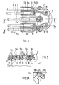
- the high voltage cables 3 to 7 are arranged on the upper part of the hollow body 2 of the removable distributor head 1 and connect, for some known as distribution 3 to 6, a spark plug with respective conductive elements 8 to 11 which, after passing through the hollow body 2, terminate inside the latter by conductive studs of equilaterally distributed distribution 13, and for the 'other said supply 7, an ignition coil (not shown) to a conductive element 12.
- the cables 3 to 6 are connected to the conductive elements 8 to 11 by end pieces 14 themselves connected to the conductive pads 13 by a metallic conductive wire 15 whose ends are force fitted into the end piece 14 and the conductive stud 13.
- the end piece 14 is shaped to receive a socket (not shown) fixed to the end of the high voltage cables.
- the conductive element 12 ends with a socket-shaped supply stud 16 which passes through the body 2 and whose bore 16 a is adapted to receive a carbon.
- distribution and supply conducting elements 8 to 12 can be produced in any other way than that described.
- the high voltage cables have their ends 3 to 7 arranged in the same conduits 17 to 21 as the conductive elements 8 to 12 which extend them and which are formed on the upper part of the body 2 .
- the most advantageous solution is to border all or part of the conduits by ribs or fins 17 a to 21 a which also surround the openings 13 a and 16 a through which pass through the studs 13 and the socket 16.
- the conduits 17 to 21 being juxtaposed with each other and each constituted by ribs forming their side walls and closing their ends around the orifices through which the studs 13 and the socket 16 pass, it follows that the high voltage cables and their conductive elements are isolated from each other by a baffle socket increasing the vanishing lines by the same amount.
- the ribs or fins 17 a to 21 a advantageously obtained from the material 2 with the body 2 by molding of insulating material, comprise near the entrances of the conduits 17 to 21 spoilers 22 projecting from the walls of said conduits and adapted to pinch and maintain the end of the high-voltage cables inside the respective conduits which receive them.
- the whole is covered by an insulating cover 23, leaving a cavity 24 having an inlet 24 a , delimited around the cables 3 to 7.
- l entry 24 a is poured a hot insulating resin to form a coating 25, in which are embedded the ends of the cables 3 to 7 and the conductive elements 8 to 11, to with the exception of the conductive pads 13 and the socket 16 projecting inside the body 2.
- the cover 23 is obtained by molding insulating material such as thermoplastic polyester.
- the cover 23 is fixed to the upper body 2 by any known means, especially by welding from a flange 23 is arranged around the cover material along the periphery of the surface covered with the upper part 2 has the body 2.
- the cover may also be fixed on the upper part 2a of the body 2 by resilient snap-fastening as shown in FIG 5A.
- the insulating body 2 has, obtained by molding, a receptacle 24A in the form of a box delimited by the walls 202.
- High voltage supply cables 7 and distribution 3 to 6 are respectively connected to current conducting elements 12 and 8 to 11 which are inserted and snapped into appropriate housings.
- the conductive supply 16 and distribution 13 pads are then inserted by force or by ultrasound into housings formed in the body 2 so as to establish contact elastic with the respective conductive elements 12 and 8 to 11.
- the cavity is designed as a receptacle 24B provided on the upper part 2 a of the body 2 and consisting of 2 said portion enclosed by a perimeter ring 27 integral with the body 2.
- a receptacle 24B provided on the upper part 2 a of the body 2 and consisting of 2 said portion enclosed by a perimeter ring 27 integral with the body 2.
- recesses 17a to 21a through which the cable ends enter 3-7 said receptacle.
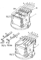
- a cover 23A which is placed in the receptacle 24A on stops 28 distributed on the inner edges of the surround 27 after having arranged the conducting elements 8A to 12A mounted in bundles 32.
- the cover 23A On its face inside, the cover 23A has a plurality of anchoring pins 29 which, trapped in the coating, hold the cover on the stops 28.
- the anchoring pins 29 have a profile adapted to have projecting parts capable of preventing the cover 23A from being torn off after polymerization of the resin.
- the conductive elements 8A to 12A are connected to each other by insulating crosspieces 30 to constitute a bundle 32. These can advantageously be produced by overmolding of insulating material on the conductive elements 8A to 12A predisposed.
- conductive elements 8A to 11A are obtained in tongues cut 33 and 34 and bent at one end to form conductive pads 13A adapted to traverse the upper part 2a of the body 2 by as many slots 31, distributed equilaterally, and protruding inside said body.
- the tongues 33 and 34 are provided with lugs 35 crimped on the high-voltage cables 3 to 6.
- the supply conductive element 12A consists of a tongue 36, one end of which is provided with a lug 35 crimped to the cable 7 and the other end welded to the socket 16.
- FIG. 11 shows an embodiment which differs essentially from the previous one in that the coating is obtained by overmolding of insulating material from the wiring harness 32 in the receptacle 24B, thus eliminating the cover 23A of FIG. 10.
- the insulating resin is poured into the receptacle 24B.
- Figure 12 reports a similar embodiment to the embodiment of Figure 11, with the exception of the surround 27 of the upper part 2a of the body 2 containing the coating 26A that has been deleted, the closer to the realization of Figures 6 and 7.
- the conductive elements which compose it consist, on the one hand of end caps 37 crimped at the end of high voltage cables 3 to 7 and in which are anchored conductive wires and, on the other hand, conductive pads 39 on the end 30 a, which the son conductors 38 are welded (fig.4) or crimped (Fig. 14a), the end 39a lying projecting from the upper portion 2a of the body 2.
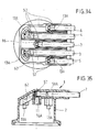
- the embodiment shown in Figures 15 to 18 is remarkable in that the coating 26B of the conductive elements is in the form of an intermediate wafer 40 on which the body 2 is molded.
- the wafer 40 can be produced by polymerization of a liquid epoxy resin in a recyclable mold.
- the conductive elements for distributing the wiring harness which are embedded in the wafer 40 consist of end pieces 41, one of the ends of which forms the conductive stud 13 b opening out inside the body 2, while the other cylindrical end 42 is arranged so as to receive, by elastic snap-fastening, a tubular terminal 43 crimped at the end of the supply cables 7 and distribution cables 3 to 6 (FIG. 18).
- the supply conductive element at the end of the cable 7 differs essentially from the above supply conductive elements in that the conductive stud 13 b is replaced by a socket-shaped supply stud 16 whose bore is suitable to receive a charcoal (not shown).
- the wafer 40 has a plurality of slots 44 into which the overmolding material (PBTP) of the body 2 of the removable distributor head 1 penetrates (FIG. 17).
- PBTP overmolding material
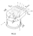
- FIG. 19 to 25 The embodiment shown in Figures 19 to 25 is similar to that of Figures 15 to 18 and differs essentially in that the coating 26 c which is in the form of a wafer 40A is produced after positioning the ends of the cables 3 to 7 extended by the conducting elements 8 to 12 on a plate of form 45 from which said wafer is molded (Fig. 20).
- Figures 19 and 20 show the plate 45 which has a base plate 46 in which are formed recesses 52, 53.
- the recesses 52 are suitable for receiving the distribution conductive studs 13 while the recess 53 is designed to receive the supply conductive stud 16.
- Small columns 47 are staggered on the upper face of the base plate 46, the front end staggered one near 46 a of the plate 45 by which open the high voltage cable 3 to 7, in two rows approximately parallel.
- the high voltage cables 3 to 7 are directed between the balusters 47 so that they follow an approximately zigzag path in order to then be brought, outside the plate, in directions approximately parallel to each other and on the same plane by through a bar 50 which they pass through by wire clamps 51 (fig. 20).
- the form plate 45 once fitted with the bundle of cables 3 to 7, is placed in a mold (not shown) in which the coating operation is carried out by molding the wafer 40A.
- indentations 55 to form, during the operation of molding the wafer 40A, anchoring fingers 54 projecting from both sides. on the other side of the wafer 40A (Figs. 21 and 22).
- the wafer 40A After molding and separation of the form plate 45 the wafer 40A has as many orifices 48 which pass through it as there are small posts 47 that the plate 45 included (FIG. 21).
- the material which composes it flows in the orifices 48 of the wafer 40A, constituting by filling the anchoring crosspieces 49 (FIG. 25).
- Such an embodiment allows, by the anchoring fingers 52 and the crosspieces 49, a joining effective mechanics of the wafer 40A to the body 2 of the distributor and high resistance to tearing of the high voltage cables from the distributor head.
- connection of the wafer 40A in the body 2 of the dispensing head is all the stronger as the insulating resin which composes said wafer is chemically compatible with the insulating material composing the body 2.
- a brass blank is cut out and has an electrical supply conductor 12A ending at one of its ends by a patch 50 and by a rectangular part 51.
- Other electrical distribution conductors 8A to 11A are obtained by cutting the brass blank and are connected to each other and to conductor 12A, by bridges 52.
- the other end of each of the supply and distribution conductors 12A 8A to 11A ends in the form of sheets 53 aligned and located on the same plane, and terminated for example by an anchoring end piece 53 a .
- the ends 54 of the electrical distribution conductors 8A to 11A are bent at 90 ° so as to form distribution pads 13A, and the rectangular part 51 is also folded at 90 ° and wound up so as to form a supply pad 16 in socket shape, the patch 50 of which forms the bottom.
- End pieces 55 are locked on the plug-shaped ends 53 of the conductive elements 8A to 12A, after the cables 3 to 7 have been crimped into the slotted tubular part of the end pieces 55 provided for establishing electrical contact with the core of the cables 3 to 7.
- the assembly thus formed is overmolded with an insulating material to form a coating 58 (FIG. 27) leaving only the bridges 52 which, after hardening of the coating 58 forming a compact assembly, are broken (FIG. 28) in order '' electrically isolate the electrical supply conductors 12A and distribution 8A to 11A.
- This operation can also take place after installation of the sub-assembly ( Figure 28) in the final overmolding mold.
- the coating 58 has a crenellated portion 59 thanks to which the said coating 58 will be firmly integrated with the overmolding of a second insulating material in order to produce the body 2 (FIG. 29) of the dispenser head 1.
- FIGS. 30 and 31 differs slightly from the previous embodiment in that, in the cut brass blank, as previously described, the ends 54 of the distribution conductors 8A to 11A are bent at 90 ° to constitute studs distribution 13, while the supply pad 16 is obtained by folding the rectangle 51 and by the pad 50.
- the cut circuit thus obtained is directly overmolded with an insulating material simultaneously constituting the coating 58A and the body 2.
- the removal of the bridges 52 and the bending of the ends 54 of the distribution conductors 8A to 11A take place automatically during of the overmolding operation.
- an insulating support 60 comprises five channels, one 61 for supply and the other 62 for distribution bordered by wings or partitions 63, the support insulator 60 includes the housing 13 a and 16 a of the power supply pad 16 and 13A distribution pads which are obtained by cutting and are inserted after molding.
- High-voltage cables 3 to 7 are arranged in the corresponding channels 61 and 62 and are connected to their respective studs using end caps 57 provided for this purpose locking like the end pieces 55. The assembly thus obtained is coated by overmolding the insulating body 2 so as to constitute a distributor head 1 integrating said insulating body 2 and the high-voltage cables 3 to 7.
- the filling of the cavity 24 ( Figure 1) by the resin can be effected by at least one hole 2b formed in the wall of the upper part 2a of the body 2 as by any location of the receptacle or body 2.
- the filling can also be carried out from any location on the body 2, the orifices 2 b serving as vents.
Landscapes
- Engineering & Computer Science (AREA)
- Chemical & Material Sciences (AREA)
- Combustion & Propulsion (AREA)
- Mechanical Engineering (AREA)
- General Engineering & Computer Science (AREA)
- Architecture (AREA)
- Civil Engineering (AREA)
- Structural Engineering (AREA)
- Manufacturing & Machinery (AREA)
- Ignition Installations For Internal Combustion Engines (AREA)
- Connector Housings Or Holding Contact Members (AREA)
- Electrostatic Spraying Apparatus (AREA)
Applications Claiming Priority (2)
| Application Number | Priority Date | Filing Date | Title |
|---|---|---|---|
| FR8803817A FR2629139B1 (fr) | 1988-03-23 | 1988-03-23 | Tete amovible de distributeur d'allumage a faisceau de cables haute tension integre pour moteur a combustion interne de vehicule automobile |
| FR8803817 | 1988-03-23 |
Publications (2)
| Publication Number | Publication Date |
|---|---|
| EP0335051A2 true EP0335051A2 (de) | 1989-10-04 |
| EP0335051A3 EP0335051A3 (de) | 1990-07-18 |
Family
ID=9364575
Family Applications (1)
| Application Number | Title | Priority Date | Filing Date |
|---|---|---|---|
| EP88402397A Withdrawn EP0335051A3 (de) | 1988-03-23 | 1988-09-23 | Abnehmbarer Kopf von Zündverteilern mit integriertem Hochspannungskabelbündel für Brennkraftmaschinen von Fahrzeugen |
Country Status (2)
| Country | Link |
|---|---|
| EP (1) | EP0335051A3 (de) |
| FR (1) | FR2629139B1 (de) |
Cited By (2)
| Publication number | Priority date | Publication date | Assignee | Title |
|---|---|---|---|---|
| EP0542005A1 (de) * | 1991-11-09 | 1993-05-19 | kabelmetal electro GmbH | Verfahren zur Herstellung einer elektrisch leitenden Verbindung zwischen zwei elektrischen Leitungen |
| WO1997004941A1 (de) * | 1995-07-25 | 1997-02-13 | Robert Bosch Gmbh | Verfahren zur elektrischen verbindung zweier elektrischer bauteile miteinander |
Citations (6)
| Publication number | Priority date | Publication date | Assignee | Title |
|---|---|---|---|---|
| FR3737E (fr) * | 1904-02-02 | 1905-02-21 | Louis Renault | Dispositif d'allumage à distributeur indépendant pour moteurs à explosions |
| FR953715A (fr) * | 1947-10-03 | 1949-12-12 | Ducellier Ets | Perfectionnement aux distributeurs d'allumage |
| DE1904824A1 (de) * | 1969-01-31 | 1970-10-01 | Webster Millard Anderson | Rotierender Zuendverteiler |
| FR2220892A1 (en) * | 1973-03-07 | 1974-10-04 | Ducellier & Cie | Distributor leads for use on I.C. engine - are secured in metal socket ensuring electrical connection between wire and socket |
| DE3609475A1 (de) * | 1985-03-23 | 1987-04-09 | Sumitomo Wiring Systems | Verbindungsvorrichtung fuer das zuendungssystem von kraftfahrzeugen |
| US4658103A (en) * | 1986-02-07 | 1987-04-14 | Mac Patrick McAbee | Distributor for multi-cylinder engine |
-
1988
- 1988-03-23 FR FR8803817A patent/FR2629139B1/fr not_active Expired - Fee Related
- 1988-09-23 EP EP88402397A patent/EP0335051A3/de not_active Withdrawn
Patent Citations (6)
| Publication number | Priority date | Publication date | Assignee | Title |
|---|---|---|---|---|
| FR3737E (fr) * | 1904-02-02 | 1905-02-21 | Louis Renault | Dispositif d'allumage à distributeur indépendant pour moteurs à explosions |
| FR953715A (fr) * | 1947-10-03 | 1949-12-12 | Ducellier Ets | Perfectionnement aux distributeurs d'allumage |
| DE1904824A1 (de) * | 1969-01-31 | 1970-10-01 | Webster Millard Anderson | Rotierender Zuendverteiler |
| FR2220892A1 (en) * | 1973-03-07 | 1974-10-04 | Ducellier & Cie | Distributor leads for use on I.C. engine - are secured in metal socket ensuring electrical connection between wire and socket |
| DE3609475A1 (de) * | 1985-03-23 | 1987-04-09 | Sumitomo Wiring Systems | Verbindungsvorrichtung fuer das zuendungssystem von kraftfahrzeugen |
| US4658103A (en) * | 1986-02-07 | 1987-04-14 | Mac Patrick McAbee | Distributor for multi-cylinder engine |
Cited By (4)
| Publication number | Priority date | Publication date | Assignee | Title |
|---|---|---|---|---|
| EP0542005A1 (de) * | 1991-11-09 | 1993-05-19 | kabelmetal electro GmbH | Verfahren zur Herstellung einer elektrisch leitenden Verbindung zwischen zwei elektrischen Leitungen |
| US5231758A (en) * | 1991-11-09 | 1993-08-03 | Kabelmetal Electro Gmbh | Process for producing an electrical connection between two electric lines |
| WO1997004941A1 (de) * | 1995-07-25 | 1997-02-13 | Robert Bosch Gmbh | Verfahren zur elektrischen verbindung zweier elektrischer bauteile miteinander |
| US6161282A (en) * | 1995-07-25 | 2000-12-19 | Robert Bosch Gmbh | Process and device for the electrical connection of two electrical components to each other |
Also Published As
| Publication number | Publication date |
|---|---|
| EP0335051A3 (de) | 1990-07-18 |
| FR2629139B1 (fr) | 1993-07-02 |
| FR2629139A1 (fr) | 1989-09-29 |
Similar Documents
| Publication | Publication Date | Title |
|---|---|---|
| EP0735629B1 (de) | Vorrichtung für die Verbindung von elektrischen Leitungsdrähten und Anschlussblock ausgerüstet mit obiger Vorrichtung | |
| EP0500168A1 (de) | Verfahren zur Herstellung eines elektronischen Moduls für eine Speicherkarte und elektronisches, nach diesem Verfahren hergestelltes Modul | |
| FR2777732A1 (fr) | Agencement de connexion electrique | |
| FR2788888A1 (fr) | Connecteur electrique pour cable plat | |
| FR2534083A1 (fr) | Connecteur de borne de bobine de champ pour ensembles de stator | |
| FR2738406A1 (fr) | Prise electrique pourvue d'un etrier | |
| EP0312415B1 (de) | Leiterplatten für hohe Ströme und Verfahren zur Herstellung | |
| EP0395512B1 (de) | Zündspule, insbesondere für Brennkraftmaschinen eines Kraftfahrzeuges und Mittel zur Sicherung des primären Zusammenbaus innerhalb des sekundären | |
| FR2772914A1 (fr) | Dispositif capteur, notamment de vitesse de roue de vehicule | |
| EP0335051A2 (de) | Abnehmbarer Kopf von Zündverteilern mit integriertem Hochspannungskabelbündel für Brennkraftmaschinen von Fahrzeugen | |
| EP0619691B1 (de) | Glasscheibe mit Anschlusselement | |
| EP0669696B1 (de) | Modulare Speise- und Steuereinheit für einen Wechselstromgenerator eines Fahrzeugs | |
| EP0669695A1 (de) | Verbesserte Speise- und Steuereinheit für einen Wechselstromgenerator eines Fahrzeugs | |
| EP0230811B1 (de) | Zündspule mit geschlossenem magnetischem Kreis | |
| EP0101359B1 (de) | Gehäuse für elektrische Verbindungen | |
| EP0093029B1 (de) | Elektronischer Regler für Wechselstromgeneratoren von Automobilen | |
| EP0557143B1 (de) | Gehäuse für ein Bündel elektrischer Leitungen verbindbar mit Anschlussklemmen | |
| WO2016008798A1 (fr) | Dispositif et procédé de connexion d'un moteur électrique | |
| EP0255409B1 (de) | Elektrische Verbindungen des Sekundärkreises einer Zündspule | |
| EP0750388B1 (de) | Wechselstromgenerator für ein Kraftfahrzeug mit einer Bürstentragplatte mit umgossenem Entstörkondensator | |
| EP0268502B1 (de) | Klammerförmiges Kabelendstück für Zündverteilerdeckel | |
| EP0135438A1 (de) | Anschliessbares elektrisches Gehäuse | |
| FR2622255A1 (fr) | Bobine double d'allumage, en particulier pour moteur a combustion interne de vehicule automobile, et circuit conducteur des enroulements primaires pour une telle bobine | |
| EP0030486B1 (de) | Stromrichter-Zusammenbau | |
| EP0277443B1 (de) | Verbindungsband zur Herstellung von elektrischen Komponenten |
Legal Events
| Date | Code | Title | Description |
|---|---|---|---|
| PUAI | Public reference made under article 153(3) epc to a published international application that has entered the european phase |
Free format text: ORIGINAL CODE: 0009012 |
|
| AK | Designated contracting states |
Kind code of ref document: A2 Designated state(s): DE FR IT SE |
|
| RAP1 | Party data changed (applicant data changed or rights of an application transferred) |
Owner name: VALEO ELECTRONIQUE |
|
| RAP3 | Party data changed (applicant data changed or rights of an application transferred) |
Owner name: VALEO ELECTRONIQUE |
|
| PUAL | Search report despatched |
Free format text: ORIGINAL CODE: 0009013 |
|
| AK | Designated contracting states |
Kind code of ref document: A3 Designated state(s): DE FR IT SE |
|
| 17P | Request for examination filed |
Effective date: 19900802 |
|
| 17Q | First examination report despatched |
Effective date: 19921204 |
|
| RAP1 | Party data changed (applicant data changed or rights of an application transferred) |
Owner name: SAGEM ALLUMAGE |
|
| RAP1 | Party data changed (applicant data changed or rights of an application transferred) |
Owner name: VALEO ELECTRONIQUE |
|
| RAP1 | Party data changed (applicant data changed or rights of an application transferred) |
Owner name: SAGEM ALLUMAGE |
|
| STAA | Information on the status of an ep patent application or granted ep patent |
Free format text: STATUS: THE APPLICATION IS DEEMED TO BE WITHDRAWN |
|
| 18D | Application deemed to be withdrawn |
Effective date: 19930615 |