EP0334309B1 - Appareil de distribution de papier imprimé et méthode pour sa commande - Google Patents
Appareil de distribution de papier imprimé et méthode pour sa commande Download PDFInfo
- Publication number
- EP0334309B1 EP0334309B1 EP89105085A EP89105085A EP0334309B1 EP 0334309 B1 EP0334309 B1 EP 0334309B1 EP 89105085 A EP89105085 A EP 89105085A EP 89105085 A EP89105085 A EP 89105085A EP 0334309 B1 EP0334309 B1 EP 0334309B1
- Authority
- EP
- European Patent Office
- Prior art keywords
- printed papers
- printed
- papers
- abnormality
- accumulating region
- Prior art date
- Legal status (The legal status is an assumption and is not a legal conclusion. Google has not performed a legal analysis and makes no representation as to the accuracy of the status listed.)
- Expired - Lifetime
Links
- 238000000034 method Methods 0.000 title claims description 8
- 230000005856 abnormality Effects 0.000 claims description 28
- 230000002159 abnormal effect Effects 0.000 claims description 22
- 230000003287 optical effect Effects 0.000 claims description 5
- 238000001514 detection method Methods 0.000 claims description 3
- 238000010586 diagram Methods 0.000 description 2
- 238000007689 inspection Methods 0.000 description 2
- 230000007257 malfunction Effects 0.000 description 2
- 230000003111 delayed effect Effects 0.000 description 1
- 230000000694 effects Effects 0.000 description 1
- 239000013013 elastic material Substances 0.000 description 1
- 230000001788 irregular Effects 0.000 description 1
Images


Classifications
-
- B—PERFORMING OPERATIONS; TRANSPORTING
- B65—CONVEYING; PACKING; STORING; HANDLING THIN OR FILAMENTARY MATERIAL
- B65H—HANDLING THIN OR FILAMENTARY MATERIAL, e.g. SHEETS, WEBS, CABLES
- B65H29/00—Delivering or advancing articles from machines; Advancing articles to or into piles
- B65H29/38—Delivering or advancing articles from machines; Advancing articles to or into piles by movable piling or advancing arms, frames, plates, or like members with which the articles are maintained in face contact
- B65H29/40—Members rotated about an axis perpendicular to direction of article movement, e.g. star-wheels formed by S-shaped members
-
- G—PHYSICS
- G07—CHECKING-DEVICES
- G07D—HANDLING OF COINS OR VALUABLE PAPERS, e.g. TESTING, SORTING BY DENOMINATIONS, COUNTING, DISPENSING, CHANGING OR DEPOSITING
- G07D11/00—Devices accepting coins; Devices accepting, dispensing, sorting or counting valuable papers
- G07D11/10—Mechanical details
-
- B—PERFORMING OPERATIONS; TRANSPORTING
- B65—CONVEYING; PACKING; STORING; HANDLING THIN OR FILAMENTARY MATERIAL
- B65H—HANDLING THIN OR FILAMENTARY MATERIAL, e.g. SHEETS, WEBS, CABLES
- B65H2301/00—Handling processes for sheets or webs
- B65H2301/40—Type of handling process
- B65H2301/42—Piling, depiling, handling piles
- B65H2301/421—Forming a pile
- B65H2301/4212—Forming a pile of articles substantially horizontal
-
- B—PERFORMING OPERATIONS; TRANSPORTING
- B65—CONVEYING; PACKING; STORING; HANDLING THIN OR FILAMENTARY MATERIAL
- B65H—HANDLING THIN OR FILAMENTARY MATERIAL, e.g. SHEETS, WEBS, CABLES
- B65H2701/00—Handled material; Storage means
- B65H2701/10—Handled articles or webs
- B65H2701/19—Specific article or web
- B65H2701/1912—Banknotes, bills and cheques or the like
Definitions
- the present invention relates to a printed paper dispensing apparatus for dispensing a predetermined number of printed papers in the form of bank notes, tickets or the like and a method of controlling the foregoing apparatus. More particularly, the present invention relates to a printed paper dispensing apparatus which assures that a predetermined number of printed papers in the form of bank notes, tickets or the like are conveyed to a dispensing outlet port without fail and a method of controlling the foregoing apparatus.
- a hitherto known printed paper dispensing apparatus used as a money exchanger, a ticket vender or the like is disclosed in, e.g., an official gazette of Japanese Utility Model Publication NO. 22,028/1985.
- the apparatus disclosed in the official gazette is of a type employing a blade wheel.
- the apparatus is so constructed that a predetermined number of printed papers drawn from the interior of a printed paper receiving portion are once placed one above another in a layered structure in alignment with each other while they are separated from each other one by one via a blade wheel and then all the printed papers arranged in that way are conveyed to a dispensing outlet port using a belt conveyer, rollers or the like means.
- the conventional apparatus gives an unexpected damage users or controllers of the apparatus, because when two printed papers superposed one above another or abnormal printed papers each having an irregular shape are delivered to the blade wheel, there arises a problem that they are conveyed to the dispensing outlet as they are or the apparatus is clogged with them.
- Another problem appearing in the conventional apparatus is that printed papers are sometimes accumulated while some one stands upright in an accumulating region, after they are individually separated from each other by the blade wheel. In this case, all the printed papers can not be simultaneously conveyed to the dispensing outlet port due to the presence of the printed paper which stands upright in the accumulating region, resulting in a required number of printed papers failing to be correctly dispensed thereto. The apparatus may be clogged with them under the circumstances.
- a printed paper dispensing apparatus corresponding to the precharacterizing part of claim 1 is known from US-A-3 965 913.
- bank notes are drawn from a receiving section and individually separated by means which places the bank note one above the other on a receptacle which is arranged movably up and down along a vertical belt. In its lowermost position, the receptacle presents the bank notes at a dispensing outlet port. If the cash is not taken away, for instance if an error occurs via accumulating, the bank notes are not delivered.
- US-A-4 159 782 discloses a banking machine for dispensing bank notes.
- the banking machine dispenses the bank notes from a storage bin via an escrow station to an exit throat for delivery to the customer.
- the printed papers in the accumulating region are inched in the opposite direction to the dispensing outlet port before they are conveyed to the latter. This assures that a printed paper which stands upright in the accumulating region is tilted down onto the latter, resulting in all the printed papers being conveyed to the dispensing outlet port without fail.
- the present invention provides a printed paper dispensing apparatus which is free from a malfunction that printed papers remain midway of the conveying passage and which assures that printed papers can smoothly be conveyed to the dispensing outlet port.
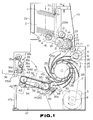
- Fig. 1 is a side view of a bank note dispensing apparatus shown with a side cover removed therefrom.
- Fig. 2 is a view illustrating the apparatus in Fig. 1, as seen from the back side.
- Fig. 3 is a side view of the apparatus, schematically illustrating that essential components constituting the apparatus are turned to their opened state.
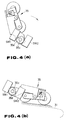
- Figs. 4(a) and 4(b) are a side view of a thrust roller, respectively, illustrating a manner of detecting two positions assumed by the thrust roller.
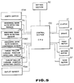
- Fig. 5 is a block diagram illustrating by way of example a control system for the apparatus.
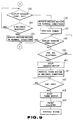
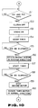
- Figs. 6 to 11 are a flowchart, respectively, illustrating operations of the control system in Fig. 5, and
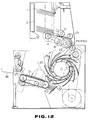
- Figs. 12 to 19 are a side view of the apparatus illustrating operations thereof, respectively.
- Figs. 1 and 2 illustrate a money exchanger in which a bank note dispensing apparatus in accordance with the present invention is incorporated, wherein Fig. 1 is a side view of the exchanger with an outer cover removed therefrom and Fig. 2 is a view showing the exchanger as seen from the back side.
- a number of bank notes 1 representative of printed papers to be dispensed from the exchanger are received in a bank note receiving portion 2 in a layered structure.
- the bank note receiving portion 2 is provided with a weight 3 adapted to slide downward along a guide 2a to depress the bank notes 1 from the above.
- the bank notes 1 in the bank note receiving portion 2 are drawn from the lowest part of the layered structure one by one by means of a roller 4.
- the roller 4 is driven by a first motor 5 via a pulley 6, a belt 7, a pulley 8, a shaft 9, a clutch 10, a belt 11, a pulley 12, a shaft 13, a pulley 14, a belt 15, a pulley 16 and a shaft 17.
- a brake 18 is mounted on the shaft 17 for the purpose of controlling the driving of the roller 4.
- a pair of rollers 19 are operatively associated with the roller 4 via a belt 20 and a pair of rollers 21 are arranged above the roller 19.
- An one-way clutch (not shown) is provided for the roller 21 so that among the layered bank notes to be conveyed, bank notes exclusive the lowermost one are inhibited from being conveyed. Consequently, only the lowermost bank note is drawn from the bank note receiving portion 2.
- This bank note moves between rollers 22 fixedly mounted on the shaft 13 and rollers 23 kept in slidable contact with the rollers 22 as well as between the rollers 22 and rollers 24 kept in slidable contact with the rollers 22 until it is introduced into a space between adjacent blades 25a on a blade wheel 25.
- the respective rollers 19 and 22 are designed to have a diameter larger than that of the roller 4 and an amount of feeding by the rollers 19 and 22 is determined larger than that by the roller 4. This causes the bank notes which have been drawn by the roller 4 to be arranged one after another in an equally spaced relationship as viewed in the direction of movement of the bank notes. This is intended to facilitate detecting of the respective bank notes by sensors PX1 and PX2 which will be described later.
- the blade wheel 25 is rotated in the anticlockwise direction by the first motor 5 via the pulley 6, the belt 7, the pulley 8, a first gear 25′ coaxially mounted on the shaft for the pulley 8, a second gear 26, a third gear 27 coaxially mounted on the shaft for the second gear 26, a fourth gear 28, a fifth gear 29 coaxially mounted on the shaft of the fourth gear 28 and a sixth gear 30 coaxially mounted on the shaft 25a for the blade wheel 25.
- a single bank note held between the respective adjacent blades 25a on the blade wheel 25 is parted away from the blade wheel 25 so that bank notes are successively placed one above another in a layered structure on a belt conveyer 31.
- the belt conveyer 31 extends between pulleys 32 and 33 so that it can be driven in both normal and reverse directions by a second motor 34 via the pulley 32.
- a plurality of belt conveyers 31 each having same structure are arranged in parallel to each other, although they are not clearly shown in the drawings for the purpose of simplification of illustration.
- a thrust roller 35 is constructed by plural pairs of rollers 35b arranged in parallel to each other, each of the rollers 35b being retracted by a spring 35a.
- the thrust roller 35 is tilted in the direction identified by an arrow mark in Fig. 1 when bank notes on the belt conveyer 31 are to be conveyed toward a dispensing outlet port 36.
- the thrust roller 35 is driven by a third motor 37 via a pulley 38, a belt 39, a pulley 40, a shaft 42, a pulley 41, a belt 43 and a pulley 44.
- a thrust roller 45 adapted to be biased onto the belt conveyer 31 under the effect of resilient force of a spring 45a is provided in a region where the pulley 33 is arranged.
- a gear 46 made of elastic material to draw abnormal bank notes into an abnormal bank note receiving portion 47 is provided in the vicinity of the belt conveyer 31. The gear 46 is driven by the second motor 34 via the pulley 32, the belt conveyor 31, the pulley 33 and gears 470 and 48.
- the bank note receiving portion 2 includes a door 2b adapted to be turned about a shaft 2c to the front side, as shown in Fig. 3.
- the weight 3 is displaced upwardly along the guide 2a via a link 2d so that a number of bank notes can easily be received in a layered structure in the open space located under the weight 3 in the bank note receiving portion 2.
- a back cover 49 can be opened by turning it about a shaft 49a in the backward direction, as shown in Fig. 3. This permits the bank notes to be removed from a region where the rollers 19 and 22 are arranged, if the apparatus is clogged with them for some reason.
- the blades 25a are fitted in the hub portion of the blade wheel 25 by displacing them in the axial direction. This arrangement makes it possible to easily replace damaged or injured blades 25a with new ones.
- the abnormal bank note receiving portion 47 includes a front door 47a adapted to be opened by turning it about a shaft 47b so that abnormal bank notes in the abnormal bank note receiving portion 47 can be removed therefrom .
- the thrust roller 35 can be turned about a shaft 35c in the direction as identified by an arrow mark in Fig. 1.
- the apparatus of the present invention is equipped with a plurality of sensors for the purpose of controlling operations of the first motor 5, the second motor 34, the third motor 37, the clutch 10 and the brake 18.
- An empty switch ESW is disposed at the lower part of the bank note receiving portion 2.
- This empty switch ESW is intended to detect the fact that the number of bank otes received in a layered structure in the bank note receiving portion 2 is reduced less than a predetermined one (hereinafter referred to as an empty).
- the empty switch ESW comprises an optical sensor adapted to detect the empty by detecting the presence of a protrusion 3a protruding outwardly of the weight 3.
- Two abnormal bank note detecting sensors PX1 and PX2 for detecting an abnormality with the respective bank notes drawn in that way are disposed in a region where the rollers 22 and 24 are provided for the purpose of conveying the bank notes drawn from the bank note receiving portion 2.
- each of the sensors PX1 and PX2 comprises an optical sensor adapted to detect an abnormality with the respective bank notes in the form of two bank notes superposed one above another, abnormality of bank note in shape or the like with reference to the time when a certain bank note has moved past the sensors PX1 and PX2, the delayed timing of detection performed thereby or the like parameter.
- the apparatus of the present invention is equipped with switches SW1 and SW2 which are disposed on the pivotal shaft 35c of the thrust roller 35 to detect the current position where the thrust roller 35 has been turned.
- Each of the switches SW1 and SW2 comprises a limit switch which is actuated by a cam 35d fixedly mounted on the shaft 35c.
- Figs. 4(a) and 4(b) illustrate a state assumed by the switches SW1 and SW2 in an enlarged scale, respectively.
- the switch SW2 is turned on by the cam 35d while the switch SW1 is turned off, as shown in Fig. 4(a).
- An outlet sensor PSW1 is disposed in the proximity of the dispensing outlet port 36 so as to allow all the bank notes conveyed to the outlet port 36 by the belt conveyer 31 to be detected.
- This sensor PSW1 comprises an optical sensor.
- An abnormal bank note removal confirming sensor PSW2 is disposed in the proximity of the pulley 33 so that among the bank notes conveyed by the belt conveyer 31, abnormal bank notes to be introduced into the abnormal bank note receiving portion 47 are detected.
- the sensor PSW2 comprises an optical sensor too.
- Fig. 5 illustrates by way of block diagram the structure of a control system for the apparatus in accordance with this embodiment.
- Outputs from the aforementioned sensors, i.e., the switch ESW, the switches PX1 and PX2, the switches SW1 and SW2 and the sensors PSW1 and PSW2 are introduced into a control section (hereinafter referred to CPU) 100.
- CPU control section
- Data indicative of the number of bank notes to be dispensed from the apparatus are inputted in the CPU 100, wherein the number of bank notes has been previously set in a setting section 50.
- the CPU 100 controls operations of the first motor 5, the second motor 34, the third motor 37, the clutch 10 and the brake 18 on the basis of outputs from a number of sensors ESW, PX1, PX2, SW1, SW2, PSW1 and PSW2 as well as data set in the setting section 50.
- the number N of bank notes to be dispensed from the apparatus is set in a counter (not shown), wherein the number N of bank notes to be dispensed has been previously set in the setting section 50 (step 101).
- This counter is incorporated in the CPU 100 either in a hardware fashion or in a software fashion.
- the clutch 10 is turned off (step 102) and the brake 18 is turned on (step 103).
- the first motor 5 starts its rotation. Since the clutch 10 is turned off and the brake 18 is turned on, the blade wheel 25 starts its rotation but the roller 4 is not rotated and also the roller 19 and 22 are not rotated.
- a timer (not shown) starts its operation (step 105).
- This timer is incorporated in the CPU 100 either in a hardware fashion or in a software fashion.
- the brake 18 is turned off (107) and the clutch 10 is turned on (step 108). This causes the roller 4 and the rollers 19 and 22 to start their rotation whereby a step of drawing of the bank notes from the interior of the bank note receiving portion 2 is started.
- a period of 300 milliseconds from the starting of rotation of the first motor 5 till the starting of rotation of the roller 4 represents a period of idling which elapses until the first motor 5 assumes a stable rotational speed (i.e., until the blade wheel 25 assumes a stable rotational speed).
- the bank notes drawn from the bank note receiving portion 2 by the roller 4 are distributed in the form of a single bank note in an equally spaced relationship as viewed in the direction of movement of the bank notes by means of the rollers 19 as well as the rollers 21 of which rotational direction is defined by the one-way clutch. Thereafter, the singularly distributed bank note reaches via the rollers 22 and 23 the position where the sensors PX1 and PX2 are disposed so that inspection is performed as to whether it is normal or abnormal.
- step 109 when it is detected that the sensors PX1 and PX2 are turned on (step 109), a determination is made on the basis of outputs from the sensors PX1 and PX2 as to whether or not an abnormality in the form of two bank notes superposed one above another occurs among the bank notes conveyed from the roller 4 (step 110).
- a detection is made as to whether the sensors PX1 and PX2 are turned off or not (step 111).
- a determination is then made on the basis of outputs from them as to whether the bank notes are abnormal or not in shape (step 112).
- Fig. 12 illustrates the foregoing state.
- a single bank note (a bank note 1A in the illustrated case) stands upright on the belt conveyer 31, as shown in Fig. 13.
- the latter is operated in the opposite direction to the dispensing outlet port 36 for 100 milliseconds.
- the second motor 34 is rotated in the reverse direction after rotation of the first motor 5 is interrupted at the step 119.
- This causes the belt conveyer 31 to be operated in the opposite direction to the dispensing outlet port 36 (the direction identified by an arrow mark), resulting in the bank note 1A which has stood upright being tilted down onto the conveyer belt 31 without fail.
- Operation of the timer is started in response to rotation of the second motor 34 in the reverse direction (step 121).
- step 122 rotation of the second motor 34 is interrupted (step 123) so that the third motor 37 is rotated in the normal direction (step 124).
- step 124 rotation of the third motor 37 in the normal direction
- the thrust roller 35 is turned toward the belt conveyer 31, as shown in Fig. 15.
- the switch SW2 is turned off by disengagement of the cam 35d disposed on the rotational shaft 35c of the thrust roller 35
- rotation of the third motor 37 is interrupted so that the second motor 34 is subsequently rotated in the normal direction.
- step 128 When it is detected by the sensor PSW 1 that the bank notes have been conveyed to the dispensing outlet port 36 (step 128), operation of the timer is started (step 129) and rotation of the second motor 34 is interrupted (step 131) after a period of 600 milliseconds elapses (step 130). As the second motor 34 is rotated in the normal direction, all the bank notes which have been placed one above another in a layered structure on the belt conveyer 31 are conveyed to the dispensing outlet port 36 (see Fig. 16). After rotation of the second motor 34 is interrupted, operation of the timer is started (step 132).
- the second motor 34 is rotated in the normal direction again to confirm the presence or absence of residual bank notes (step 136). Additionally, operation of the timer is started again (step 137).
- the program returns to the step 129 so that the second motor 34 is rotated further in the normal direction for 600 milliseconds.
- step 137 If the sensor PSW1 fails to be turned on even after a period of 600 milliseconds elapses after operation of the timer has been started again (step 137), rotation of the second motor 34 is interrupted (step 140) so that the third motor 37 is rotated in the reverse direction (step 141).
- step 142 When the switch SW1 is turned off by turning movement of the thrust roller 35 (step 142), rotation of the third motor 37 is interrupted (step 143). This permits the thrust roller 35 to be returned to the waiting position, as shown in Fig. 17. Thereafter, the counter is reset (step 144) and thereby the apparatus is kept in the waiting state.
- the program jumps to a step 151 in Fig. 10. If it is determined at the step 151 that the sensors PX1 and PX2 are turned off, the clutch 10 is turned off (step 152) and the brake 18 is turned on (step 153). This causes rotation of the roller 4 and the rollers 19 and 22 to be interrupted whereby drawing of the bank notes from the interior of the bank note receiving portion 2 is interrupted.
- Operation of the timer is started after the brake 18 is turned on (step 154) and then the second motor 34 is rotated in the reverse direction after a period of 500 milliseconds elapses (representative of a long period of waiting time enough to allow the bank notes which have been conveyed midway of the conveying passage to be placed on the belt conveyer 31 in a layered structure) (step 156).
- operation of the timer is started (step 157) and rotation of the second motor 34 is interrupted after a period of 100 milliseconds elapses after operation of the timer is started (step 158).
- Rotation of the second motor 34 in the reverse direction assures that a bank note which stands upright on the belt conveyer 31 is tilted down thereon without fail.
- step 161 when the third motor 37 is rotated in the normal direction (step 160) and thereby the switch SW2 is turned off (step 161), rotation of the third motor 37 is interrupted (step 162). This permits the thrust roller 35 to be turned down onto the belt conveyer 31 (see Fig. 18). Subsequently, the second motor 34 is rotated in the reverse direction (step 163). After the sensor PSW2 is turned on (step 164) and it is turned off later (step 165), operation of the timer is started and then rotation of the second motor 34 is interrupted after a period of 500 milliseconds elapses (step 168).
- step 169 When the third motor 37 is rotated in the reverse direction after rotation of the second motor 34 is interrupted (step 169) and thereby the thrust roller 35 returns to the waiting position so that the switch SW1 is turned off (step 170), rotation of the third motor 37 is interrupted (step 171).
- the program After the counter is later reset to a condition of N, the program returns to the step 105 in Fig. 6, causing bank notes to be drawn from the bank note receiving portion 2 again. Namely, the brake 18 is turned off at the step 107 and the clutch 10 is turned on at the step 108 whereby conveying of bank notes is started from the first again.
- the foregoing operations are repeated, e.g., by three times. When it is found that bank notes are not correctly dispensed from the apparatus in spite of the three repeated operations in that way, an error signal is generated.
Claims (15)
- Un appareil de distribution de papier imprimé comprenant :
un moyen de prélèvement (4) pour prélever des papiers imprimés (1), stockés dans une partie réceptrice de papier imprimé (2), de l'intérieur de celle-ci, un par un,
un moyen d'accumulation (25) pour séparer individuellement les papiers imprimés (1) prélevés par le moyen de prélèvement (4) pour pouvoir les placer les uns sur les autres selon une structure en couches dans une zone d'accumulation (31),
un moyen d'acheminement (34) pour acheminer les papiers imprimés (1) disposés dans ladite zone d'accumulation (31), jusqu'à un orifice de sortie et de distribution (36),
caractérisé par un moyen de commande (34) pour reculer les papiers imprimés (1), disposés dans la zone d'accumulation (31), dans la direction opposée à l'orifice de sortie et de distribution (36) avant de les acheminer jusqu'à ce dernier. - L'appareil selon la revendication 1, caractérisé en ce que le moyen d'acheminement (34) répète les opérations d'acheminement des papiers imprimés (1) pendant une période prédéterminée jusqu'à ce que les papiers imprimés (1) acheminés à l'orifice de sortie et de distribution (36) soit ramassés.
- L'appareil selon la revendication 1, caractérisé en ce que le moyen d'acheminement (34) effectue au moins une opération d'acheminement des papiers imprimés (1) après que les papiers imprimés acheminés à l'orifice de sortie et de distribution (36) ont été ramassés.
- L'appareil selon l'une des revendications 1 à 3, caractérisé en ce que la zone d'accumulation (31) comporte un convoyeur à bande apte à acheminer des papiers imprimés (1) à la fois dans le sens normal et en sens inverse, et en ce que le moyen de commande (34) est apte à actionner ledit convoyeur à bande en sens inverse.
- L'appareil selon l'une des revendications 1 à 4, comprenant en outre un moyen de commande de galet d'appui (SW1, SW2) pour commander un galet d'appui (35) apte à être basculé sur les papiers imprimés (1) placés dans la zone d'accumulation (31) pour leur appuyer dessus lorsque les papiers imprimés (1) placés dans la zone d'accumulation (31) doivent être acheminés jusqu'à l'orifice de sortie et de distribution (36).
- L'appareil selon l'une des revendications 1 à 4, caractérisé par
un moyen de détection de défauts (PX1, PX2) pour détecter un défaut sur les différents papiers imprimés (1) prélevés de ladite partie réceptrice de papier imprimé (2) par ledit moyen de prélèvement (4), le moyen d'accumulation (25) étant disposé après ledit moyen de détection de défauts (PX1, PX2), le moyen d'acheminement (34) étant actionné lorsqu'un laps de temps prédéterminé s'est écoulé après que le dernier papier imprimé (1) est passé devant le moyen de détection de défauts (PX1, PX2), si le nombre requis de papiers imprimés est passé devant le moyen de détection de défauts (PX1, PX2) sans qu'un défaut soit détecté, et
un moyen d'introduction pour introduire les papiers imprimés (1), disposés dans la zone d'accumulation (31), dans une partie réceptrice de papiers imprimés défectueux (47) lorsqu'un laps de temps prédéterminé s'est écoulé après l'interruption du prélèvement des papiers imprimés par le moyen de prélèvement (4), si un défaut est détecté par le moyen de détection de défauts (PX1, PX2) pendant que les papiers imprimés (1) sont accumulés dans la zone d'accumulation (31). - L'appareil selon la revendication 6, caractérisé en ce que le moyen de détection de défauts (PX1, PX2) comprend au moins deux capteurs optiques disposés sur l'axe qui coupe à angle droit l'axe de distribution des papiers imprimés (1), de façon qu' un défaut constitué par la superposition de deux papiers imprimés (1) et un défaut de forme des différents papiers imprimés (1), soient détectables.
- L'appareil selon la revendication 6 ou 7, caractérisé en ce que, si des papiers imprimés défectueux (1) sont introduits dans la partie réceptrice de papiers imprimés défectueux (47) par le moyen d'introduction, les opérations de distribution sont recommencées et répétées un nombre prédéterminé de fois jusqu'à ce qu'un nombre prédéterminé de papiers imprimés (1) soient distribués correctement.
- L'appareil selon l'une des revendications 6 à 8, comprenant en outre un moyen de commande de galet d'appui pour commander un galet d'appui (35) apte à être basculé vers le bas sur les papiers imprimés (1) placés dans la zone d'accumulation (31) pour leur appuyer dessus lorsque les papiers imprimés (1) placés dans la zone d'accumulation (31) doivent être acheminés jusqu'à l'orifice de sortie et de distribution (36) ainsi que lorsqu'ils doivent être introduits dans la partie réceptrice de papiers imprimés défectueux (47).
- L'appareil selon l'une des revendications 6 à 9, caractérisé par
un premier moyen de commande d'arrêt pour arrêter l'opération de prélèvement du moyen de prélèvement (4) lorsqu'un nombre désiré de papiers imprimés (1) est passé à travers le moyen de détection de défauts (PX1, PX2) sans que le moyen de détection de défauts (PX1, PX2) ne détecte un défaut des papiers imprimés (1),
un premier moyen de recul pour reculer les papiers imprimés (1), accumulés dans la zone d'accumulation (31), dans une direction opposée à l'orifice de sortie (36) lorsqu'un laps de temps prédéterminé s'est écoulé depuis le moment où l'opération de prélèvement a été arrêtée par le premier moyen de commande d'arrêt, le moyen d'acheminement destiné à acheminer les papiers imprimés (1) disposés dans la zone d'accumulation (31) jusqu'à l'orifice de sortie (36) étant actionné une fois que les papiers imprimés (1) ont été reculés par le premier moyen de recul,
un second moyen de commande d'arrêt pour arrêter immédiatement l'opération de prélèvement du moyen de prélèvement (4) lorsqu'un défaut des papiers imprimés (1) est détecté par le moyen de détection de défauts (PX1, PX2), et
un second moyen de recul pour reculer les papiers imprimés (1), accumulés dans la zone d'accumulation (31), dans une direction opposée à l'orifice de sortie (36) lorsqu'un laps de temps prédéterminé s'est écoulé depuis le moment où l'opération de prélèvement a été arrêtée par le second moyen de commande d'arrêt, le moyen d'introduction destiné à introduire les papiers imprimés (1) disposés dans la zone d'accumulation (31) dans la partie réceptrice de papiers défectueux (47) étant actionné une fois que les papiers imprimés (1) ont été reculés par le second moyen de recul. - L'appareil selon l'une des revendications 1 à 10, caractérisé en ce que le moyen de prélèvement comprend :
un premier moyen formant galet, possédant un premier galet (4) d'un premier diamètre, pour prélever les papiers imprimés (1) feuille à feuille dans la partie réceptrice de papier (2), et
un second moyen formant galet, possédant un second galet (19, 22) d'un second diamètre supérieur au premier diamètre du premier galet (4) du premier moyen formant galet, le second galet (19, 22) étant disposé en aval de la direction de prélèvement du premier moyen formant galet et tournant de manière synchrone avec la rotation du premier moyen formant galet. - Une méthode de commande d'un appareil de distribution de papier imprimé, comprenant :
une première phase consistant à prélever un par un des papiers imprimés (1), stockés dans une partie réceptrice de papier imprimé (2), de l'intérieur de cette dernière,
une deuxième phase consistant à détecter un défaut sur les différents papiers imprimés (1) prélevés lors de ladite première phase,
une troisième phase consistant à séparer individuellement les papiers imprimés (1) prélevés lors de la première phase, pour pouvoir les placer les uns sur les autres selon une structure en couches dans une zone d'accumulation (31),
une quatrième phase consistant à acheminer tous les papiers imprimés (1), disposés dans ladite zone d'accumulation (31), jusqu'à un orifice de sortie et de distribution (36) lorsqu'un laps de temps prédéterminé s'est écoulé après que les papiers imprimés (1) sont passés devant le moyen de détection de défauts (PX1, PX2), dans le cas où un nombre prédéterminé de papiers imprimés (1) sont placés les uns sur les autres selon une structure en couches dans la zone d'accumulation (31) sans qu'un défaut n'ait été détecté sur les différents papiers imprimés (1) lors de ladite deuxième phase, et
une cinquième phase consistant à introduire les papiers imprimés (1), disposés dans la zone d'accumulation (31), dans une partie réceptrice de papiers imprimés défectueux (47) lorsqu'un laps de temps prédéterminé s'est écoulé après que le prélèvement des papiers imprimés (1) de la partie réceptrice de papier imprimé (2) lors de la première phase a été interrompu, dans le cas où un défaut a été détecté sur les différents papiers imprimés (1) lors de la deuxième phase,
caractérisé en ce que,
après la troisième phase, les papiers imprimés (1) disposés dans la zone d'accumulation (31) sont reculés dans la direction opposée à l'orifice de sortie et de distribution (36) avant de réaliser la quatrième phase. - La méthode selon la revendication 12, comprenant une autre phase consistant à répéter l'opération d'acheminement des papiers imprimés (1) pendant un laps de temps prédéterminé jusqu'à ce que les papiers imprimés (1) acheminés à l'orifice de sortie et de distribution (36) soient ramassés.
- La méthode selon la revendication 12, comprenant une autre phase consistant à effectuer au moins une autre opération d'acheminement des papiers imprimés (1) une fois que les papiers imprimés (1) acheminés à l'orifice de sortie et de distribution (36) ont été ramassés.
- La méthode selon l'une des revendications 12 à 14, comprenant en outre une phase consistant à recommencer l'opération de distribution des papiers imprimés (1) lorsque les papiers imprimés défectueux (1) sont introduits dans la partie réceptrice de papiers imprimés défectueux (47) par le moyen d'introduction, et à répéter ladite opération un nombre prédéterminé de fois jusqu'à ce qu'un nombre prédéterminé de papiers imprimés (1) soient distribués correctement.
Applications Claiming Priority (4)
| Application Number | Priority Date | Filing Date | Title |
|---|---|---|---|
| JP63070734A JP2566438B2 (ja) | 1988-03-24 | 1988-03-24 | 紙葉類払出装置の制御装置 |
| JP63070733A JPH075216B2 (ja) | 1988-03-24 | 1988-03-24 | 紙葉類払出装置 |
| JP70734/88 | 1988-03-24 | ||
| JP70733/88 | 1988-03-24 |
Publications (3)
| Publication Number | Publication Date |
|---|---|
| EP0334309A2 EP0334309A2 (fr) | 1989-09-27 |
| EP0334309A3 EP0334309A3 (fr) | 1991-03-27 |
| EP0334309B1 true EP0334309B1 (fr) | 1995-07-12 |
Family
ID=26411865
Family Applications (1)
| Application Number | Title | Priority Date | Filing Date |
|---|---|---|---|
| EP89105085A Expired - Lifetime EP0334309B1 (fr) | 1988-03-24 | 1989-03-22 | Appareil de distribution de papier imprimé et méthode pour sa commande |
Country Status (5)
| Country | Link |
|---|---|
| US (1) | US4964517A (fr) |
| EP (1) | EP0334309B1 (fr) |
| CA (1) | CA1329221C (fr) |
| DE (1) | DE68923388T2 (fr) |
| ES (1) | ES2075003T3 (fr) |
Families Citing this family (11)
| Publication number | Priority date | Publication date | Assignee | Title |
|---|---|---|---|---|
| US5815592A (en) * | 1990-02-05 | 1998-09-29 | Cummins-Allison Corp. | Method and apparatus for discriminating and counting documents |
| JP2966197B2 (ja) * | 1992-05-29 | 1999-10-25 | 株式会社日本コンラックス | 紙幣識別装置 |
| US5687963A (en) * | 1994-11-14 | 1997-11-18 | Cummison-Allison Corp. | Method and apparatus for discriminating and counting documents |
| JP3284040B2 (ja) * | 1996-02-29 | 2002-05-20 | ローレルバンクマシン株式会社 | 紙幣処理機 |
| GB2311985A (en) * | 1996-04-13 | 1997-10-15 | Xerox Corp | Controlling access to sheets at delivery port. |
| GB9707243D0 (en) * | 1997-04-09 | 1997-05-28 | Ncr Int Inc | Self-service deposit method and apparatus |
| DE19958017B4 (de) * | 1999-12-02 | 2013-08-14 | Giesecke & Devrient Gmbh | Vorrichtung zum Sortieren von Banknoten |
| JP2001344635A (ja) * | 2000-06-02 | 2001-12-14 | Birukon Kk | 紙葉類識別計数機およびその識別計数方法 |
| DE10140101B4 (de) * | 2001-08-16 | 2013-10-31 | Giesecke & Devrient Gmbh | Blattgutstapelvorrichtung |
| DE602005016025D1 (de) * | 2004-06-04 | 2009-09-24 | Rue De Int Ltd | Maschine zur Sortierung von Dokumenten |
| KR100608078B1 (ko) * | 2004-07-16 | 2006-08-08 | 엘지엔시스(주) | 매체자동지급기 |
Family Cites Families (17)
| Publication number | Priority date | Publication date | Assignee | Title |
|---|---|---|---|---|
| JPS49110400A (fr) * | 1973-02-19 | 1974-10-21 | ||
| US4159782A (en) * | 1977-05-02 | 1979-07-03 | Docutel Corporation | Banking machine control |
| US4150757A (en) * | 1978-01-23 | 1979-04-24 | International Business Machines Corporation | Plural document stacking and subsequent selective stack transporting apparatus |
| JPS57130189A (en) * | 1981-02-02 | 1982-08-12 | Laurel Bank Machine Co | Paper money storage box with reject pool section for paper money clearing machine |
| SE8104036L (sv) * | 1981-06-29 | 1982-12-30 | Leif Lundblad | Automat for verdepapper och andra dokument sasom sedlar, checker, kvitton, allegat mm |
| JPS5839392A (ja) * | 1981-09-02 | 1983-03-08 | ロ−レルバンクマシン株式会社 | 自動入出金機におけるスタツカ支持装置 |
| US4482057A (en) * | 1981-12-30 | 1984-11-13 | Ncr Corporation | Record media dispensing apparatus |
| JPS5916094A (ja) * | 1982-07-20 | 1984-01-27 | 株式会社日本コンラックス | 紙幣受入装置 |
| JPS6056749A (ja) * | 1983-09-02 | 1985-04-02 | Omron Tateisi Electronics Co | 紙葉類処理装置 |
| US4784274A (en) * | 1983-10-03 | 1988-11-15 | Kabushiki Kaisha Nippon Coinco | Bill device |
| GB8406374D0 (en) * | 1984-03-12 | 1984-04-18 | De La Rue Syst | Sheet dispensing apparatus |
| US4570801A (en) * | 1984-03-21 | 1986-02-18 | Brannen Ralph L | Document handling machine |
| DE3422860A1 (de) * | 1984-06-20 | 1986-01-02 | Bayer Ag, 5090 Leverkusen | Verfahren und vorrichtung zur behandlung von fluessigkeiten mit kationenaustauschern und anionenaustauschern |
| FR2567666B1 (fr) * | 1984-07-13 | 1986-12-19 | Dassault Electronique | Dispositif distributeur de billets de banque |
| JPS6149736U (fr) * | 1984-09-03 | 1986-04-03 | ||
| GB8505759D0 (en) * | 1985-03-06 | 1985-04-11 | De La Rue Syst | Assembling sheets into stack |
| JP2547775B2 (ja) * | 1987-06-23 | 1996-10-23 | 住友電気工業株式会社 | Ofケ−ブル |
-
1989
- 1989-03-22 DE DE68923388T patent/DE68923388T2/de not_active Expired - Fee Related
- 1989-03-22 EP EP89105085A patent/EP0334309B1/fr not_active Expired - Lifetime
- 1989-03-22 ES ES89105085T patent/ES2075003T3/es not_active Expired - Lifetime
- 1989-03-23 CA CA000594645A patent/CA1329221C/fr not_active Expired - Fee Related
- 1989-03-24 US US07/328,474 patent/US4964517A/en not_active Expired - Lifetime
Also Published As
| Publication number | Publication date |
|---|---|
| DE68923388T2 (de) | 1995-12-21 |
| CA1329221C (fr) | 1994-05-03 |
| US4964517A (en) | 1990-10-23 |
| EP0334309A2 (fr) | 1989-09-27 |
| EP0334309A3 (fr) | 1991-03-27 |
| ES2075003T3 (es) | 1995-10-01 |
| DE68923388D1 (de) | 1995-08-17 |
Similar Documents
| Publication | Publication Date | Title |
|---|---|---|
| EP0616963B1 (fr) | Appareil de manipulation de feuilles | |
| EP0148877B1 (fr) | Distributeur de billets de banque | |
| EP0334309B1 (fr) | Appareil de distribution de papier imprimé et méthode pour sa commande | |
| EP0273746B1 (fr) | Dispositif d'empilement et d'emballage de pièces de monnaie | |
| EP0532217B1 (fr) | Procédé et dispositif pour empiler des notes de banque et d'autres choses semblables | |
| EP0471578B1 (fr) | Appareil de manipulation de feuilles | |
| JPH0127940B2 (fr) | ||
| JP3105298B2 (ja) | 紙幣搬送装置 | |
| US4516899A (en) | Sheet feeding apparatus | |
| US4877232A (en) | Paper discharge apparatus | |
| JPH10338367A (ja) | シート送り装置 | |
| EP2270754B1 (fr) | Dispositif de traitement de pièces de monnaie | |
| JP2566438B2 (ja) | 紙葉類払出装置の制御装置 | |
| RU2165103C2 (ru) | Система перемещения и отведения назад квитанций для банковского автомата (варианты) и способ работы банковского автомата (варианты) | |
| JPH075216B2 (ja) | 紙葉類払出装置 | |
| JP5992269B2 (ja) | 硬貨処理機および硬貨処理方法 | |
| US4221372A (en) | Machine for collating sheet material | |
| JPH07134786A (ja) | 硬貨分離繰出装置 | |
| JPH082758Y2 (ja) | 双方向硬貨払い出し機 | |
| JPH07106805B2 (ja) | 紙葉類繰出し部の紙詰り自動除去装置 | |
| JPH0237083Y2 (fr) | ||
| JPS6236590B2 (fr) | ||
| JPH0825646B2 (ja) | 紙葉類自動取扱装置 | |
| KR20000007043A (ko) | 지폐자동지급기의 지폐자동지급방법 | |
| JPS63127968A (ja) | 電子写真装置におけるロ−ル紙有無検知装置 |
Legal Events
| Date | Code | Title | Description |
|---|---|---|---|
| PUAI | Public reference made under article 153(3) epc to a published international application that has entered the european phase |
Free format text: ORIGINAL CODE: 0009012 |
|
| 17P | Request for examination filed |
Effective date: 19890322 |
|
| AK | Designated contracting states |
Kind code of ref document: A2 Designated state(s): DE ES FR GB IT SE |
|
| PUAL | Search report despatched |
Free format text: ORIGINAL CODE: 0009013 |
|
| AK | Designated contracting states |
Kind code of ref document: A3 Designated state(s): DE ES FR GB IT SE |
|
| 17Q | First examination report despatched |
Effective date: 19930422 |
|
| GRAA | (expected) grant |
Free format text: ORIGINAL CODE: 0009210 |
|
| AK | Designated contracting states |
Kind code of ref document: B1 Designated state(s): DE ES FR GB IT SE |
|
| REF | Corresponds to: |
Ref document number: 68923388 Country of ref document: DE Date of ref document: 19950817 |
|
| ET | Fr: translation filed | ||
| ITF | It: translation for a ep patent filed |
Owner name: ING. A. GIAMBROCONO & C. S.R.L. |
|
| REG | Reference to a national code |
Ref country code: ES Ref legal event code: FG2A Ref document number: 2075003 Country of ref document: ES Kind code of ref document: T3 |
|
| PLBE | No opposition filed within time limit |
Free format text: ORIGINAL CODE: 0009261 |
|
| STAA | Information on the status of an ep patent application or granted ep patent |
Free format text: STATUS: NO OPPOSITION FILED WITHIN TIME LIMIT |
|
| 26N | No opposition filed | ||
| PGFP | Annual fee paid to national office [announced via postgrant information from national office to epo] |
Ref country code: GB Payment date: 19980223 Year of fee payment: 10 |
|
| PGFP | Annual fee paid to national office [announced via postgrant information from national office to epo] |
Ref country code: FR Payment date: 19980317 Year of fee payment: 10 |
|
| PGFP | Annual fee paid to national office [announced via postgrant information from national office to epo] |
Ref country code: ES Payment date: 19980318 Year of fee payment: 10 |
|
| PGFP | Annual fee paid to national office [announced via postgrant information from national office to epo] |
Ref country code: SE Payment date: 19980320 Year of fee payment: 10 |
|
| PGFP | Annual fee paid to national office [announced via postgrant information from national office to epo] |
Ref country code: DE Payment date: 19980428 Year of fee payment: 10 |
|
| PG25 | Lapsed in a contracting state [announced via postgrant information from national office to epo] |
Ref country code: GB Free format text: LAPSE BECAUSE OF NON-PAYMENT OF DUE FEES Effective date: 19990322 |
|
| PG25 | Lapsed in a contracting state [announced via postgrant information from national office to epo] |
Ref country code: SE Free format text: LAPSE BECAUSE OF NON-PAYMENT OF DUE FEES Effective date: 19990323 Ref country code: ES Free format text: LAPSE BECAUSE OF NON-PAYMENT OF DUE FEES Effective date: 19990323 |
|
| EUG | Se: european patent has lapsed |
Ref document number: 89105085.8 |
|
| GBPC | Gb: european patent ceased through non-payment of renewal fee |
Effective date: 19990322 |
|
| PG25 | Lapsed in a contracting state [announced via postgrant information from national office to epo] |
Ref country code: FR Free format text: LAPSE BECAUSE OF NON-PAYMENT OF DUE FEES Effective date: 19991130 |
|
| EUG | Se: european patent has lapsed |
Ref document number: 89105085.8 |
|
| REG | Reference to a national code |
Ref country code: FR Ref legal event code: ST |
|
| PG25 | Lapsed in a contracting state [announced via postgrant information from national office to epo] |
Ref country code: DE Free format text: LAPSE BECAUSE OF NON-PAYMENT OF DUE FEES Effective date: 20000101 |
|
| REG | Reference to a national code |
Ref country code: ES Ref legal event code: FD2A Effective date: 20010503 |
|
| PG25 | Lapsed in a contracting state [announced via postgrant information from national office to epo] |
Ref country code: IT Free format text: LAPSE BECAUSE OF NON-PAYMENT OF DUE FEES;WARNING: LAPSES OF ITALIAN PATENTS WITH EFFECTIVE DATE BEFORE 2007 MAY HAVE OCCURRED AT ANY TIME BEFORE 2007. THE CORRECT EFFECTIVE DATE MAY BE DIFFERENT FROM THE ONE RECORDED. Effective date: 20050322 |