EP0334295A2 - Procédé et dispositif de façonnage de corps tubulaires - Google Patents
Procédé et dispositif de façonnage de corps tubulaires Download PDFInfo
- Publication number
- EP0334295A2 EP0334295A2 EP89105047A EP89105047A EP0334295A2 EP 0334295 A2 EP0334295 A2 EP 0334295A2 EP 89105047 A EP89105047 A EP 89105047A EP 89105047 A EP89105047 A EP 89105047A EP 0334295 A2 EP0334295 A2 EP 0334295A2
- Authority
- EP
- European Patent Office
- Prior art keywords
- blank
- tubular body
- die
- stopper
- cross
- Prior art date
- Legal status (The legal status is an assumption and is not a legal conclusion. Google has not performed a legal analysis and makes no representation as to the accuracy of the status listed.)
- Withdrawn
Links
Images

Classifications
-
- B—PERFORMING OPERATIONS; TRANSPORTING
- B21—MECHANICAL METAL-WORKING WITHOUT ESSENTIALLY REMOVING MATERIAL; PUNCHING METAL
- B21D—WORKING OR PROCESSING OF SHEET METAL OR METAL TUBES, RODS OR PROFILES WITHOUT ESSENTIALLY REMOVING MATERIAL; PUNCHING METAL
- B21D15/00—Corrugating tubes
- B21D15/02—Corrugating tubes longitudinally
-
- B—PERFORMING OPERATIONS; TRANSPORTING
- B21—MECHANICAL METAL-WORKING WITHOUT ESSENTIALLY REMOVING MATERIAL; PUNCHING METAL
- B21C—MANUFACTURE OF METAL SHEETS, WIRE, RODS, TUBES, PROFILES OR LIKE SEMI-MANUFACTURED PRODUCTS OTHERWISE THAN BY ROLLING; AUXILIARY OPERATIONS USED IN CONNECTION WITH METAL-WORKING WITHOUT ESSENTIALLY REMOVING MATERIAL
- B21C1/00—Manufacture of metal sheets, wire, rods, tubes or like semi-manufactured products by drawing
- B21C1/16—Metal drawing by machines or apparatus in which the drawing action is effected by means other than drums, e.g. by a longitudinally-moved carriage pulling or pushing the work or stock for making metal sheets, rods or tubes
- B21C1/22—Metal drawing by machines or apparatus in which the drawing action is effected by means other than drums, e.g. by a longitudinally-moved carriage pulling or pushing the work or stock for making metal sheets, rods or tubes specially adapted for making tubular articles
- B21C1/24—Metal drawing by machines or apparatus in which the drawing action is effected by means other than drums, e.g. by a longitudinally-moved carriage pulling or pushing the work or stock for making metal sheets, rods or tubes specially adapted for making tubular articles by means of mandrels
-
- B—PERFORMING OPERATIONS; TRANSPORTING
- B21—MECHANICAL METAL-WORKING WITHOUT ESSENTIALLY REMOVING MATERIAL; PUNCHING METAL
- B21C—MANUFACTURE OF METAL SHEETS, WIRE, RODS, TUBES, PROFILES OR LIKE SEMI-MANUFACTURED PRODUCTS OTHERWISE THAN BY ROLLING; AUXILIARY OPERATIONS USED IN CONNECTION WITH METAL-WORKING WITHOUT ESSENTIALLY REMOVING MATERIAL
- B21C37/00—Manufacture of metal sheets, rods, wire, tubes, profiles or like semi-manufactured products, not otherwise provided for; Manufacture of tubes of special shape
- B21C37/06—Manufacture of metal sheets, rods, wire, tubes, profiles or like semi-manufactured products, not otherwise provided for; Manufacture of tubes of special shape of tubes or metal hoses; Combined procedures for making tubes, e.g. for making multi-wall tubes
- B21C37/15—Making tubes of special shape; Making tube fittings
- B21C37/155—Making tubes with non-circular section
Definitions
- the invention relates to a method for pulling tubular bodies made of tubular, round blanks with a rectangular cross section, in particular for pulling one-piece copper molds for the continuous casting of steel, the inside dimension of which is predetermined by a support and the outside dimension of which is influenced by a die cooperating therewith. Furthermore, the invention relates to a drawing tool for performing this method.
- a method of the type mentioned is known from DE-OS 18 09 633.
- Blanks made of copper are formed into molds for continuous casting by inserting a mandrel into the blanks as a support, which corresponds to the entire length of the tubular body to be produced, and which specifies the internal dimension in that the blank undergoes cold deformation on the mandrel.
- the finished tubular body is removed from the mandrel by pressing the mandrel out using a suitable pressure tool.
- This method is initially tied to expensive tools, since the inner dimension of the tubular body must be produced over its entire length by a mandrel of at least the same length. Furthermore, several individual processes must be carried out one after the other until the finished tubular body is available.
- the object of the invention is to create a method and a drawing tool suitable for executing it in such a way that the tool complexity and the number of machining steps to be carried out are reduced.
- the invention solves this problem by means of the method proposed in claim 1, for the implementation of which the suggestions of subclaims 2 to 5 relate to advantageous drawing tools.
- the method according to the invention is designed as a forming process in which the blank is compressed and expanded in places during the same pass becomes.
- the material cross section is retained, the wall thickness of the tubular body produced being essentially the same as the wall thickness of the blank.
- Copper in particular, is suitable as the material of the tubular body, as is customary for continuous casting molds.
- the rectangular cross section is preferably square. Due to the material displacement, the forming process is so optimal that, contrary to other known drawing processes, the finished tubular body is formed in a single material pass.
- the cross-sectional size of the outlet gap is dimensioned equal to that of the blank intended for the forming.
- the corner areas are expanded in comparison with the blank and the central edge areas are reduced.
- This cross-sectional design requires transitions that are formed to avoid disturbing the forming of continuous surfaces.
- the stopper is arranged against rotation with respect to the die, and is expediently supported at the end of a stopper rod by the punch of a push bench, which likewise supports the die which is concentric with it.
- the support stamp can, for example, carry the means of securing against rotation.
- the blank can be pressed over the drawing tool formed in this form, provided that its ratio of length to diameter still allows this. It is expedient to press with a short tube section which has the same dimensions as the blank and is pressed with it through the drawing tool. This short tube section is then scrapped, whereas the tube body is formed with practically no loss of material.
- the stopper rod is held at its free end with the stopper in the die, while pressure is exerted on the free end of the blank by means of pliers, under which the blank slides into the formed tool.
- the deformed piece then emerges from the tool, it is gripped by means of pliers and continues to be pulled only by the latter through the tool.
- FIG. 1 shows the cross-sectional comparison of a tubular, round blank (4) with the finished tubular body (7), which is of square cross-section.
- the same wall thickness of the blank (4) and the tubular body (7) is characteristic of the invention.
- the outer circumference of the blank (4) is equal to the outer circumference of the tubular body (7) and that the inner circumference of the blank (4) is equal to the inner circumference of the tubular body (7).
- Compliance with these requirements leads to an expansion of the blank (4) in the corner region (5) of the tubular body and a compression of the blank (4) in the central edge region (6) of the tubular body. Since the cross sections of the blank (4) and tubular body (7) are the same or almost the same, the material flow in the longitudinal direction of the objects is less than perpendicular to the longitudinal extent.
- the distance from the longitudinal axis (9) in the central region of the tubular body (6) is smaller than that of the blank from the longitudinal axis ( 9), whereas in the edge area (5) of the tubular body (7) the relationship is reversed.
- This asymmetry is particularly evident in the sectional view corresponding to section line AB.
- the stopper (1) is held by the stopper rod (2), which is fixed to a push bench, non-rotatably relative to the die (3), so that the predetermined cross-sectional condition can be maintained by the interaction of stopper and die.
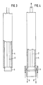
- the forming example shown in FIG. 2 provides for the blank (4) to be pressed by the drawing tool formed, the die (3) of which has a support (11) in the push bench opposite to the pressure direction (10).
- Figure 3 shows the blank prepared for drawing, which is only loosely placed on the stopper rod.
- the supercritical length of the blank is the reason to start pulling instead of pressing.
- traction means (8) act on the finished tubular body, while the stopper rod (2) is held at its free end by means of a clamping. In this arrangement, too, the stopper and the die are non-rotatable with respect to one another, so that the rectangular forming gap is retained.
Landscapes
- Engineering & Computer Science (AREA)
- Mechanical Engineering (AREA)
- Metal Extraction Processes (AREA)
Applications Claiming Priority (2)
| Application Number | Priority Date | Filing Date | Title |
|---|---|---|---|
| DE3810033 | 1988-03-25 | ||
| DE19883810033 DE3810033A1 (de) | 1988-03-25 | 1988-03-25 | Verfahren und werkzeug zum ziehen von rohrkoerpern |
Publications (2)
| Publication Number | Publication Date |
|---|---|
| EP0334295A2 true EP0334295A2 (fr) | 1989-09-27 |
| EP0334295A3 EP0334295A3 (fr) | 1990-10-17 |
Family
ID=6350625
Family Applications (1)
| Application Number | Title | Priority Date | Filing Date |
|---|---|---|---|
| EP19890105047 Withdrawn EP0334295A3 (fr) | 1988-03-25 | 1989-03-21 | Procédé et dispositif de façonnage de corps tubulaires |
Country Status (2)
| Country | Link |
|---|---|
| EP (1) | EP0334295A3 (fr) |
| DE (1) | DE3810033A1 (fr) |
Family Cites Families (5)
| Publication number | Priority date | Publication date | Assignee | Title |
|---|---|---|---|---|
| US1685636A (en) * | 1928-01-20 | 1928-09-25 | Kemp Joseph | Tube-drawing plug |
| DE843834C (de) * | 1944-04-19 | 1952-07-14 | Deutsche Edelstahlwerke Ag | Verfahren und Vorrichtung zum Ziehen von Hohlkoerpern |
| DE1809633C3 (de) * | 1968-11-19 | 1979-10-31 | Kabel- Und Metallwerke Gutehoffnungshuette Ag, 3000 Hannover | Verfahren zur Herstellung einer gebogenen Durchlaufkokille für Kreisbogenstranggußmaschinen |
| DE2806368C3 (de) * | 1978-02-10 | 1980-09-25 | Mannesmann Ag, 4000 Duesseldorf | Verfahren und Ziehanordnung zum Kaltziehen von Rohren |
| IT1160132B (it) * | 1983-12-14 | 1987-03-04 | Tubi Italia Spa | Procedimento per la preparazione di comchiglie tubolari destinate ad impianti per la colata continua di acciaio |
-
1988
- 1988-03-25 DE DE19883810033 patent/DE3810033A1/de not_active Withdrawn
-
1989
- 1989-03-21 EP EP19890105047 patent/EP0334295A3/fr not_active Withdrawn
Also Published As
| Publication number | Publication date |
|---|---|
| DE3810033A1 (de) | 1989-10-05 |
| EP0334295A3 (fr) | 1990-10-17 |
Similar Documents
| Publication | Publication Date | Title |
|---|---|---|
| DE69906093T2 (de) | Verfahren zum hydroformen von rohrförmigen bauteilen | |
| DE2557764C3 (de) | Verfahren und Vorrichtung zur Formung eines Tiefbettfelgenrohlings | |
| DE69604521T2 (de) | Herstellung eines Metallbehälters in einer Form | |
| DE3433515A1 (de) | Verfahren und werkzeug zum plastischen verformen metallischer werkstuecke durch kaltfliesspressen | |
| DE3824699C2 (de) | Verfahren zum Herstellen eines rotationssymmetrischen Hohlkörpers mit einer durchgehenden, axial sich erstreckenden zentralen Öffnung und einer umlaufenden, nutenförmigen Einschnürung in der Außenfläche durch spanlose Umformung eines massiven zylindrichen Rohlings | |
| EP0347369A2 (fr) | Procédé et dispositif d'élargissement hydraulique de profils creux | |
| DE1946178C3 (de) | Verfahren zur Herstellung von Innenprofilen in rohrförmigen Werkstücken | |
| DE69710640T2 (de) | Verfahren zur Erhöhung der Wanddicke von Metallrohren | |
| DE19508632C2 (de) | Verfahren zum Verbinden eines ersten Bauteiles mit einem zweiten Bauteil | |
| DE3424276C2 (fr) | ||
| DE69308101T2 (de) | Verfahren zur Befestigung eines rohrförmigen Verstärkungseinsatzes in eine metallische rohrförmige Struktur und Vorrichtung zur Anwendung des Verfahrens | |
| DE19820124C2 (de) | Verfahren zur Herstellung eines Rohres zur Verwendung in einem Lenkgestänge | |
| EP0085388B1 (fr) | Procédé de fabrication d'un manchon métallique à partir d'une pièce tubulaire cylindrique | |
| EP1024913B1 (fr) | Procede et dispositif pour produire un arbre a partir d'un element tubulaire | |
| DE4032424C2 (de) | Verfahren und Vorrichtung zur Herstellung von gefalzten Rohren | |
| DE69322965T2 (de) | Verfahren zur herstellung von rohrförmigen elementen mit integralen äusserlichen vorsprüngen | |
| DE4004008C1 (fr) | ||
| DE4444857C1 (de) | Verfahren und Vorrichtung zur Herstellung mindestens einer Öffnung in der Wandung eines rohrartigen Teils | |
| DE19903684B4 (de) | Werkzeug zum Querfließpressen | |
| DE3816090C2 (fr) | ||
| EP0334295A2 (fr) | Procédé et dispositif de façonnage de corps tubulaires | |
| DE69207755T2 (de) | Verfahren zum Verbinden von Warmaustauscherelementen an einer Platte und Werkzeug zum Verformen des Rohrendes von einem länglichen Durchschnitt zu einem kreisförmigen Durchschnitt | |
| DE102019002187B4 (de) | Verfahren und Vorrichtung zum Herstellen eines Bauteils mit Gewinde | |
| DE19837131C2 (de) | Verfahren zum Innenhochdruck-Umformen zweier oder mehrerer Hohlkörper mit jeweils zumindest einer Öffnung, insbesondere Metallrohre oder Metallhohlprofile sowie Innenhochdruck-Umformmaschine zur Durchführung des Verfahrens | |
| DE3943368C2 (de) | Vorrichtung zum Herstellen eines Faltenbalg- oder Wellrohrs |
Legal Events
| Date | Code | Title | Description |
|---|---|---|---|
| PUAI | Public reference made under article 153(3) epc to a published international application that has entered the european phase |
Free format text: ORIGINAL CODE: 0009012 |
|
| AK | Designated contracting states |
Kind code of ref document: A2 Designated state(s): BE DE ES FR GB IT LU NL |
|
| PUAL | Search report despatched |
Free format text: ORIGINAL CODE: 0009013 |
|
| AK | Designated contracting states |
Kind code of ref document: A3 Designated state(s): BE DE ES FR GB IT LU NL |
|
| 17P | Request for examination filed |
Effective date: 19901031 |
|
| 17Q | First examination report despatched |
Effective date: 19920817 |
|
| STAA | Information on the status of an ep patent application or granted ep patent |
Free format text: STATUS: THE APPLICATION IS DEEMED TO BE WITHDRAWN |
|
| 18D | Application deemed to be withdrawn |
Effective date: 19931001 |