EP0334295A2 - Method and apparatus for shaping tubular bodies - Google Patents
Method and apparatus for shaping tubular bodies Download PDFInfo
- Publication number
- EP0334295A2 EP0334295A2 EP89105047A EP89105047A EP0334295A2 EP 0334295 A2 EP0334295 A2 EP 0334295A2 EP 89105047 A EP89105047 A EP 89105047A EP 89105047 A EP89105047 A EP 89105047A EP 0334295 A2 EP0334295 A2 EP 0334295A2
- Authority
- EP
- European Patent Office
- Prior art keywords
- blank
- tubular body
- die
- stopper
- cross
- Prior art date
- Legal status (The legal status is an assumption and is not a legal conclusion. Google has not performed a legal analysis and makes no representation as to the accuracy of the status listed.)
- Withdrawn
Links
Images

Classifications
-
- B—PERFORMING OPERATIONS; TRANSPORTING
- B21—MECHANICAL METAL-WORKING WITHOUT ESSENTIALLY REMOVING MATERIAL; PUNCHING METAL
- B21D—WORKING OR PROCESSING OF SHEET METAL OR METAL TUBES, RODS OR PROFILES WITHOUT ESSENTIALLY REMOVING MATERIAL; PUNCHING METAL
- B21D15/00—Corrugating tubes
- B21D15/02—Corrugating tubes longitudinally
-
- B—PERFORMING OPERATIONS; TRANSPORTING
- B21—MECHANICAL METAL-WORKING WITHOUT ESSENTIALLY REMOVING MATERIAL; PUNCHING METAL
- B21C—MANUFACTURE OF METAL SHEETS, WIRE, RODS, TUBES OR PROFILES, OTHERWISE THAN BY ROLLING; AUXILIARY OPERATIONS USED IN CONNECTION WITH METAL-WORKING WITHOUT ESSENTIALLY REMOVING MATERIAL
- B21C1/00—Manufacture of metal sheets, metal wire, metal rods, metal tubes by drawing
- B21C1/16—Metal drawing by machines or apparatus in which the drawing action is effected by other means than drums, e.g. by a longitudinally-moved carriage pulling or pushing the work or stock for making metal sheets, bars, or tubes
- B21C1/22—Metal drawing by machines or apparatus in which the drawing action is effected by other means than drums, e.g. by a longitudinally-moved carriage pulling or pushing the work or stock for making metal sheets, bars, or tubes specially adapted for making tubular articles
- B21C1/24—Metal drawing by machines or apparatus in which the drawing action is effected by other means than drums, e.g. by a longitudinally-moved carriage pulling or pushing the work or stock for making metal sheets, bars, or tubes specially adapted for making tubular articles by means of mandrels
-
- B—PERFORMING OPERATIONS; TRANSPORTING
- B21—MECHANICAL METAL-WORKING WITHOUT ESSENTIALLY REMOVING MATERIAL; PUNCHING METAL
- B21C—MANUFACTURE OF METAL SHEETS, WIRE, RODS, TUBES OR PROFILES, OTHERWISE THAN BY ROLLING; AUXILIARY OPERATIONS USED IN CONNECTION WITH METAL-WORKING WITHOUT ESSENTIALLY REMOVING MATERIAL
- B21C37/00—Manufacture of metal sheets, bars, wire, tubes or like semi-manufactured products, not otherwise provided for; Manufacture of tubes of special shape
- B21C37/06—Manufacture of metal sheets, bars, wire, tubes or like semi-manufactured products, not otherwise provided for; Manufacture of tubes of special shape of tubes or metal hoses; Combined procedures for making tubes, e.g. for making multi-wall tubes
- B21C37/15—Making tubes of special shape; Making tube fittings
- B21C37/155—Making tubes with non circular section
Abstract
Description
Die Erfindung bezieht sich auf ein Verfahren zum Ziehen von mit rechteckigem Querschnitt ausgeführten Rohrkörpern aus rohrförmigen, runden Rohlingen, insbesondere zum Ziehen von einteiligen Kupferkokillen für das Stranggießen von Stahl, deren Innenmaß von einer Abstützung und deren Außenmaß von einer damit zusammenwirkenden Matritze vorgegeben wird. Weiterhin bezieht sich die Erfindung auf ein Ziehwerkzeug zur Durchführung dieses Verfahrens.The invention relates to a method for pulling tubular bodies made of tubular, round blanks with a rectangular cross section, in particular for pulling one-piece copper molds for the continuous casting of steel, the inside dimension of which is predetermined by a support and the outside dimension of which is influenced by a die cooperating therewith. Furthermore, the invention relates to a drawing tool for performing this method.
Ein Verfahren der genannten Art ist nach der DE-OS 18 09 633 bekannt. Dabei werden Rohlinge aus Kupfer zu Kokillen für das Stranggießen umgeformt, indem in die Rohlinge als Abstützung ein Dorn eingebracht wird, welcher dem herzustellenden Rohrkörper in seiner gesamten Länge entspricht, und der das Innenmaß dadurch vorgibt, daß der Rohling auf dem Dorn eine Kaltverformung erfährt. Nach diesem Vorgang, durch den eine Kaltverfestigung des Werkstofffes hervorgerufen wird, wird der fertige Rohrkörper vom Dorn entfernt, indem der Dorn mittels eines geeigneten Druckwerkzeuges herausgedrückt wird. Dieses Verfahren ist zunächst an aufwendige Werkzeuge gebunden, da das Innenmaß des Rohrkörpers auf seiner gesamten Länge durch einen mindestens gleichlang ausgeführten Dorn erzeugt werden muß. Weiterhin sind mehrere Einzelvorgänge nacheinander auszuführen, bis der fertige Rohrkörper vorliegt.A method of the type mentioned is known from DE-OS 18 09 633. Blanks made of copper are formed into molds for continuous casting by inserting a mandrel into the blanks as a support, which corresponds to the entire length of the tubular body to be produced, and which specifies the internal dimension in that the blank undergoes cold deformation on the mandrel. After this process, which causes work hardening of the material, the finished tubular body is removed from the mandrel by pressing the mandrel out using a suitable pressure tool. This method is initially tied to expensive tools, since the inner dimension of the tubular body must be produced over its entire length by a mandrel of at least the same length. Furthermore, several individual processes must be carried out one after the other until the finished tubular body is available.
Hiervon ausgehend liegt der Erfindung die Aufgabenstellung zugrunde, ein Verfahren und ein zu dessen Ausführung geeignetes Ziehwerkzeug derart zu schaffen, daß der Werkzeugaufwand sowie die Anzahl der vorzunehmenden Bearbeitungsschritte herabgesetzt werden.Proceeding from this, the object of the invention is to create a method and a drawing tool suitable for executing it in such a way that the tool complexity and the number of machining steps to be carried out are reduced.
Die Erfindung löst diese Aufgabenstellung durch das im Patentanspruch 1 vorgeschlagene Verfahren, zu dessen Durchführung die Vorschläge der Unteransprüche 2 bis 5 vorteilhafte Ziehwerkzeuge betreffen.The invention solves this problem by means of the method proposed in claim 1, for the implementation of which the suggestions of subclaims 2 to 5 relate to advantageous drawing tools.
Auf diese Weise gestaltet sich das erfindungsgemäße Verfahren als ein Umformprozeß, bei welchem der Rohling während des gleichen Durchgangs stellenweise gestaucht und stellenweise aufgeweitet wird. Insgesamt bleibt der Materialquerschnitt erhalten, wobei die Wandstärke des erzeugten Rohrkörpers der Wandstärke des Rohlings im wesentlichen gleich ist. Als Werkstoff des Rohrkörpers kommt insbesondere Kupfer in Betracht, wie es für Stranggießkokillen üblich ist. Der rechteckige Querschnitt ist dabei bevorzugt quadratisch. Aufgrund der Materialverdrängungen gestaltet sich der Umformprozeß derart optimal, daß, entgegen anderen bekannten Ziehverfahren, der fertige Rohrkörper in einem einzigen Materialdurchgang gebildet wird. Gegenüber dem gattungsgemäß zugrunde gelegten Stand der Technik besteht der Vorteil, daß es, ohne auf die durch Kaltumformung bedingte Kaltverfestigung zu verzichten, möglich ist, bereits am Ende des Umformvorganges den fertigen Rohrkörper zu erhalten, der nicht erst noch von seinem Dorn befreit werden muß. Zugleich ist das Werkzeug wesentlich weniger aufwendig. Lediglich der Stopfen bedarf einer Anpassung an den herzustellenden Innenquerschnitt, während die den Stopfen tragende Stopfenstange weitgehend frei und entsprechend wenig aufwendig ausgeführt werden kann.In this way, the method according to the invention is designed as a forming process in which the blank is compressed and expanded in places during the same pass becomes. Overall, the material cross section is retained, the wall thickness of the tubular body produced being essentially the same as the wall thickness of the blank. Copper, in particular, is suitable as the material of the tubular body, as is customary for continuous casting molds. The rectangular cross section is preferably square. Due to the material displacement, the forming process is so optimal that, contrary to other known drawing processes, the finished tubular body is formed in a single material pass. Compared to the generic state of the art, there is the advantage that it is possible to obtain the finished tubular body at the end of the forming process, which does not have to be freed from its mandrel, without having to do without the strain hardening caused by cold forming. At the same time, the tool is much less complex. Only the stopper needs to be adapted to the inner cross section to be produced, while the stopper rod carrying the stopper can be designed largely freely and accordingly with little effort.
Für die Ausbildung des erfindungsgemäßen Ziehwerkzeuges, welches aus Stopfen und Matritze besteht, ist die Querschnittsgröße des Austrittsspaltes gleich derjenigen des für die Umformung vorgesehenen Rohlings bemessen. Nach Maßgabe dieser Bedingung sind im Vergleich um Rohling die Eckenbereiche aufgeweitet und die mittigen Kantenbereiche reduziert. Diese Querschnittsgestaltung bedingt Übergänge, die zur Vermeidung einer Störung der Umformung von kontinuierlichen Flächen gebildet sind.For the design of the drawing tool according to the invention, which consists of a stopper and a die, the cross-sectional size of the outlet gap is dimensioned equal to that of the blank intended for the forming. In accordance with this condition, the corner areas are expanded in comparison with the blank and the central edge areas are reduced. This cross-sectional design requires transitions that are formed to avoid disturbing the forming of continuous surfaces.
Der Stopfen wird im Bezug zur Matritze verdrehungssicher angeordnet, wobei er zweckmäßig am Ende einer Stopfenstange vom Stempel einer Stoßbank abgestützt ist, die gleichfalls die dazu konzentrische Matritze abstützt. Der Stützstempel kann beispielsweise die Mittel der Verdrehungssicherung tragen. Über das in dieser Form gebildete Ziehwerkzeug läßt sich der Rohling drücken, sofern sein Verhältnis von Länge zu Durchmesser dies noch gestattet. Gedrückt wird zweckmäßig mit einem kurzen Rohrabschnitt, der gleiche Abmessungen wie der Rohling besitzt und mit diesem durch das Ziehwerkzeug gedrückt wird. Dieser kurze Rohrabschnitt wird anschließend verschrottet, wohingegen der Rohrkörper praktisch ohne Materialverlust gebildet wird.The stopper is arranged against rotation with respect to the die, and is expediently supported at the end of a stopper rod by the punch of a push bench, which likewise supports the die which is concentric with it. The support stamp can, for example, carry the means of securing against rotation. The blank can be pressed over the drawing tool formed in this form, provided that its ratio of length to diameter still allows this. It is expedient to press with a short tube section which has the same dimensions as the blank and is pressed with it through the drawing tool. This short tube section is then scrapped, whereas the tube body is formed with practically no loss of material.
Für den Fall, daß das Verhältnis von Länge zu Durchmesser des Rohlings das Mindestmaß überschreitet, wird die Stopfenstange an ihrem freien Ende mit dem Stopfen in der Matritze gehalten, während am freien Ende des Rohlings mittels einer Zange Druck ausgeübt wird, unter welchem sich der Rohling in das gebildete Werkzeug einschiebt. Wenn alsdann das verformte Stück aus dem Werkzeug austritt, wird es mittels einer Zange ergriffen und weiterhin lediglich von dieser durch das Werkzeug gezogen.In the event that the ratio of length to diameter of the blank exceeds the minimum, the stopper rod is held at its free end with the stopper in the die, while pressure is exerted on the free end of the blank by means of pliers, under which the blank slides into the formed tool. When the deformed piece then emerges from the tool, it is gripped by means of pliers and continues to be pulled only by the latter through the tool.
Zur weiteren Veranschaulichung der Erfindung wird auf die sich auf ein Ausführungsbeispiel beziehenden Zeichnungen Bezug genommen. Darin zeigen:
- Figur 1 die Querschnittsmaße des Rohlings und des Rohrkörpers,
- Figur 2 ein Ziehwerkzeug im Querschnitt,
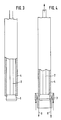
Figur 3 einen für das Ziehen vorbereiteten Rohling undFigur 4 eine Darstellung des Ziehvorganges.
- 1 shows the cross-sectional dimensions of the blank and the tubular body,
- FIG. 2 shows a drawing tool in cross section,
- Figure 3 is a blank prepared for drawing and
- Figure 4 is an illustration of the drawing process.
Man erkennt gemäß Figur 1 die Querschnittsgegenüberstellung eines rohrförmigen, runden Rohlings (4) mit dem fertigen Rohrkörper (7), der von quadratischem Querschnitt ist. Kennzeichnend für die Erfindung ist die gleiche Wandstärke des Rohlings (4) und des Rohrkörpers (7). Weiterhin besteht die Bedingung, daß der Außenumfang des Rohlings (4) gleich dem Außenumfang des Rohrkörpers (7) ist, und daß der Innenumfang des Rohlings (4) gleich dem Innenumfang des Rohrkörpers (7) ist. Die Einhaltung dieser Voraussetzungen führt im Eckenbereich (5) des Rohrkörpers zu einer Aufweitung des Rohlings (4) und im mittleren Kantenbereich (6) des Rohrkörpers zu einer Stauchung des Rohlings (4). Da die Querschnitte vom Rohling (4) und Rohrkörper (7) gleich bzw. nahezu gleich sind, kommt es bei der Umformung in der Längsrichtung der Gegenstände weniger zu einem Materialfluß als senkrecht zur Längserstreckung.1 shows the cross-sectional comparison of a tubular, round blank (4) with the finished tubular body (7), which is of square cross-section. The same wall thickness of the blank (4) and the tubular body (7) is characteristic of the invention. There is also the condition that the outer circumference of the blank (4) is equal to the outer circumference of the tubular body (7) and that the inner circumference of the blank (4) is equal to the inner circumference of the tubular body (7). Compliance with these requirements leads to an expansion of the blank (4) in the corner region (5) of the tubular body and a compression of the blank (4) in the central edge region (6) of the tubular body. Since the cross sections of the blank (4) and tubular body (7) are the same or almost the same, the material flow in the longitudinal direction of the objects is less than perpendicular to the longitudinal extent.
Demnach ergibt sich für das in Figur 2 dargestellte, aus dem Stopfen (1) und der Matritze (3) bestehende Ziehwerkzeug, daß im Mittenbereich des Rohrkörpers (6) der Abstand von der Längsachse (9) kleiner als derjenige des Rohlings von der Längsachse (9) ist, wohingegen im Kantenbereich (5) des Rohrkörpers (7) die Beziehung umgekehrt ist. Bei der Schnittdarstellung entsprechend der Schnittlinie AB wird diese Asymmetrie besonders deutlich. Der Stopfen (1) wird dabei von der Stopfenstange (2), die an einer Stoßbank fixiert ist, unverdrehbar gegenüber der Matritze (3) gehalten, so daß sich die vorgegebene Querschnittsbedingung durch das Zusammenwirken von Stopfen und Matritze einhalten läßt. Das in Figur 2 dargestellte Umformbeispiel sieht ein Drücken des Rohlings (4) durch das gebildete Ziehwerkzeug vor, dessen Matritze (3) entgegengesetzt zur Druckrichtung (10) eine Abstützung (11) in der Stoßbank aufweist.Accordingly, for the drawing tool shown in FIG. 2 and consisting of the plug (1) and the die (3), the distance from the longitudinal axis (9) in the central region of the tubular body (6) is smaller than that of the blank from the longitudinal axis ( 9), whereas in the edge area (5) of the tubular body (7) the relationship is reversed. This asymmetry is particularly evident in the sectional view corresponding to section line AB. The stopper (1) is held by the stopper rod (2), which is fixed to a push bench, non-rotatably relative to the die (3), so that the predetermined cross-sectional condition can be maintained by the interaction of stopper and die. The forming example shown in FIG. 2 provides for the blank (4) to be pressed by the drawing tool formed, the die (3) of which has a support (11) in the push bench opposite to the pressure direction (10).
Figur 3 zeigt den für das Ziehen vorbereiteten Rohling, der lediglich lose auf die Stopfenstange aufgesetzt ist. In diesem Falle ist die überkritische Länge des Rohlings Anlaß dafür, anstatt des Drückens zum Ziehen überzugehen. Dabei greifen, wie Figur 4 zeigt, Zugmittel (8) am fertigen Rohrkörper an, während die Stopfenstange (2) an ihrem freien Ende mittels einer Einspannung gehalten ist. Auch bei dieser Anordnung sind der Stopfen und die Matritze mit der Maßgabe in Bezug zueinander unverdrehbar, so daß der rechteckige Umformspalt erhalten bleibt.Figure 3 shows the blank prepared for drawing, which is only loosely placed on the stopper rod. In this case, the supercritical length of the blank is the reason to start pulling instead of pressing. As shown in FIG. 4, traction means (8) act on the finished tubular body, while the stopper rod (2) is held at its free end by means of a clamping. In this arrangement, too, the stopper and the die are non-rotatable with respect to one another, so that the rectangular forming gap is retained.
Claims (5)
dadurch gekennzeichnet,
daß die Abstützung mittels eines im Querschnitt rechteckigen Stopfens (1) am Ende einer Stopfenstange (2) erfolgt, dessen größter Umfang dem Innenumfang des Rohlings (4) und des späteren Rohrkörpers (7) gleich ist, während der Außenumfang des Rohrkörpers (7) von einer Matritze (3) mit gleichem Innenumfang wie der Außenumfang des Rohlings (4) geformt wird.1.Procedure for drawing rectangular-section tubular bodies (7) from tubular, round blanks, (4) in particular for pulling one-piece copper molds for the continuous casting of steel, the inside dimensions of which are supported and the outside dimensions of a cooperating die (3 ) is specified,
characterized,
that the support is provided by means of a stopper (1) with a rectangular cross section at the end of a stopper rod (2), the largest circumference of which is equal to the inner circumference of the blank (4) and the later tubular body (7), while the outer circumference of the tubular body (7) is from a die (3) with the same inner circumference as the outer circumference of the blank (4) is formed.
dadurch gekennzeichnet,
daß der Stopfen (1) und die Matritze (3) für die Umformung des Rohlings (4) eine mit letzerem übereinstimmende Querschnittsgröße aufweisen, und daß die Querschnittsmaße einerseits im Eckenbereich (5) des Umformquerschnittes aufgeweitet und andererseits im mittigen Kantenbereich (6) des Umformquerschnittes reduziert sind, wobei die Übergänge von jeweils kontinuierlichen Flächen gebildet sind.2. drawing tool for performing the method according to claim 1,
characterized,
that the stopper (1) and the die (3) for the forming of the blank (4) have a cross-sectional size that matches the latter, and that the cross-sectional dimensions are widened on the one hand in the corner area (5) of the forming cross section and on the other hand in the central edge area (6) of the forming cross section are reduced, the transitions being formed by continuous surfaces.
dadurch gekennzeichnet,
daß Mittel für die verdrehungssichere Anordnung des Stopfens (1) zur Matritze (3) vorgesehen sind.3. drawing tool according to claim 2,
characterized,
that means are provided for the twist-proof arrangement of the plug (1) to the die (3).
daß der Stopfen (1) am Ende einer Stopfenstange (2) angebracht und bodenseitig vom Stempel einer Stoßbank abgestützt ist, die dazu konzentrisch gleichfalls die Matritze (3) abstützt, und daß der Rohling (4) über dieses gebildete Werkzeug zu drücken ist.4. Drawing tool according to claims 2 and 3, characterized in
that the stopper (1) is attached to the end of a stopper rod (2) and is supported at the bottom by the punch of a push bench, which also concentrically supports the die (3), and that the blank (4) is to be pressed over this tool.
dadurch gekennzeichnet,
daß die Stopfenstange (2) an ihrem freien Ende mit dem Stopfen (1) an der Matritze (3) gehalten ist, und daß im Rohrkörper (7) nach Austritt aus diesem gebildeten Werkzeug Zugmittel (8) angreifen.5. drawing tool according to claims 2 and 3,
characterized,
that the stopper rod (2) is held at its free end with the stopper (1) on the die (3), and that in the tubular body (7) after exiting from this tool, pulling means (8) act.
Applications Claiming Priority (2)
| Application Number | Priority Date | Filing Date | Title |
|---|---|---|---|
| DE3810033 | 1988-03-25 | ||
| DE19883810033 DE3810033A1 (en) | 1988-03-25 | 1988-03-25 | METHOD AND TOOL FOR DRAWING TUBE BODIES |
Publications (2)
| Publication Number | Publication Date |
|---|---|
| EP0334295A2 true EP0334295A2 (en) | 1989-09-27 |
| EP0334295A3 EP0334295A3 (en) | 1990-10-17 |
Family
ID=6350625
Family Applications (1)
| Application Number | Title | Priority Date | Filing Date |
|---|---|---|---|
| EP19890105047 Withdrawn EP0334295A3 (en) | 1988-03-25 | 1989-03-21 | Method and apparatus for shaping tubular bodies |
Country Status (2)
| Country | Link |
|---|---|
| EP (1) | EP0334295A3 (en) |
| DE (1) | DE3810033A1 (en) |
Citations (4)
| Publication number | Priority date | Publication date | Assignee | Title |
|---|---|---|---|---|
| US1685636A (en) * | 1928-01-20 | 1928-09-25 | Kemp Joseph | Tube-drawing plug |
| CH495799A (en) * | 1968-11-19 | 1970-09-15 | Kabel Metallwerke Ghh | Process for the production of a permanent mold made of a metallic tube for continuous casting machines |
| DE2806368A1 (en) * | 1978-02-10 | 1979-08-16 | Mannesmann Ag | Tube cold drawing tool - uses consecutive hollow-, plug-, hollow-, and rod drawing elements |
| GB2151162A (en) * | 1983-12-14 | 1985-07-17 | Tubi Italia Spa | Method for preparing tubular chills for continuous steel casting plants |
Family Cites Families (1)
| Publication number | Priority date | Publication date | Assignee | Title |
|---|---|---|---|---|
| DE843834C (en) * | 1944-04-19 | 1952-07-14 | Deutsche Edelstahlwerke Ag | Method and device for drawing hollow bodies |
-
1988
- 1988-03-25 DE DE19883810033 patent/DE3810033A1/en not_active Withdrawn
-
1989
- 1989-03-21 EP EP19890105047 patent/EP0334295A3/en not_active Withdrawn
Patent Citations (4)
| Publication number | Priority date | Publication date | Assignee | Title |
|---|---|---|---|---|
| US1685636A (en) * | 1928-01-20 | 1928-09-25 | Kemp Joseph | Tube-drawing plug |
| CH495799A (en) * | 1968-11-19 | 1970-09-15 | Kabel Metallwerke Ghh | Process for the production of a permanent mold made of a metallic tube for continuous casting machines |
| DE2806368A1 (en) * | 1978-02-10 | 1979-08-16 | Mannesmann Ag | Tube cold drawing tool - uses consecutive hollow-, plug-, hollow-, and rod drawing elements |
| GB2151162A (en) * | 1983-12-14 | 1985-07-17 | Tubi Italia Spa | Method for preparing tubular chills for continuous steel casting plants |
Also Published As
| Publication number | Publication date |
|---|---|
| EP0334295A3 (en) | 1990-10-17 |
| DE3810033A1 (en) | 1989-10-05 |
Similar Documents
| Publication | Publication Date | Title |
|---|---|---|
| DE2250323C3 (en) | Method and apparatus for joining a metal pipe to a metal splined rod | |
| DE3433515A1 (en) | METHOD AND TOOL FOR PLASTICALLY FORMING METAL WORKPIECES BY COLD FLOW PRESSING | |
| EP0347369A2 (en) | Method and apparatus for hydraulically enlarging hollow profiles | |
| DE2557764C3 (en) | Method and device for forming a drop center rim blank | |
| DE1946178C3 (en) | Process for the production of inner profiles in tubular workpieces | |
| DE3824699C2 (en) | Method for producing a rotationally symmetrical hollow body with a continuous, axially extending central opening and a circumferential, groove-shaped constriction in the outer surface by non-cutting shaping of a solid cylindrical blank | |
| DE3424276C2 (en) | ||
| DE19820124C2 (en) | Method of making a pipe for use in a steering linkage | |
| EP0085388B1 (en) | Method of making a metal socket starting from a cylindrical tubular piece | |
| DE4032424C2 (en) | Method and device for producing folded pipes | |
| DE10119839A1 (en) | Method for manufacturing an axle element for motor vehicles | |
| EP1024913B1 (en) | Method and device for producing a shaft from a tubular workpiece | |
| DE4004008C1 (en) | ||
| DE4444857C1 (en) | Method for forming opening in wall of esp. exhaust pipe | |
| DE19903684B4 (en) | Tool for cross extrusion | |
| DE3816090C2 (en) | ||
| WO2000010746A2 (en) | Method for deforming through high inner pressure at least two hollow bodies having each at least one opening, especially metal tubes or metal hollow profiles | |
| EP0334295A2 (en) | Method and apparatus for shaping tubular bodies | |
| DE19837131C2 (en) | Process for hydroforming two or more hollow bodies, each with at least one opening, in particular metal pipes or hollow metal profiles, and hydroforming machine for carrying out the process | |
| DE3943368C2 (en) | Device for producing a bellows or corrugated pipe | |
| EP0615794B1 (en) | Method to produce a plug chamber for cascade drawing of tubes and device for carrying out the method | |
| DE102019000032A1 (en) | Method for forming at least one opening on a hollow profile, device for carrying out such a method | |
| DE1261102B (en) | Method and device for the manufacture of pipe bends with a cross section that tapers evenly from one end to the other | |
| DE3201263C2 (en) | Method and device for manufacturing a sealing ring assembly | |
| DE2706396C2 (en) | Method for producing a permanent connection between parts of a pipe and a closure |
Legal Events
| Date | Code | Title | Description |
|---|---|---|---|
| PUAI | Public reference made under article 153(3) epc to a published international application that has entered the european phase |
Free format text: ORIGINAL CODE: 0009012 |
|
| AK | Designated contracting states |
Kind code of ref document: A2 Designated state(s): BE DE ES FR GB IT LU NL |
|
| PUAL | Search report despatched |
Free format text: ORIGINAL CODE: 0009013 |
|
| AK | Designated contracting states |
Kind code of ref document: A3 Designated state(s): BE DE ES FR GB IT LU NL |
|
| 17P | Request for examination filed |
Effective date: 19901031 |
|
| 17Q | First examination report despatched |
Effective date: 19920817 |
|
| STAA | Information on the status of an ep patent application or granted ep patent |
Free format text: STATUS: THE APPLICATION IS DEEMED TO BE WITHDRAWN |
|
| 18D | Application deemed to be withdrawn |
Effective date: 19931001 |