EP0334020B1 - Doppelschrägkeil - Google Patents
Doppelschrägkeil Download PDFInfo
- Publication number
- EP0334020B1 EP0334020B1 EP89102749A EP89102749A EP0334020B1 EP 0334020 B1 EP0334020 B1 EP 0334020B1 EP 89102749 A EP89102749 A EP 89102749A EP 89102749 A EP89102749 A EP 89102749A EP 0334020 B1 EP0334020 B1 EP 0334020B1
- Authority
- EP
- European Patent Office
- Prior art keywords
- wedge
- double
- slope
- halves
- another
- Prior art date
- Legal status (The legal status is an assumption and is not a legal conclusion. Google has not performed a legal analysis and makes no representation as to the accuracy of the status listed.)
- Expired - Lifetime
Links
- 238000006073 displacement reaction Methods 0.000 claims description 2
- 238000003475 lamination Methods 0.000 claims 4
- 238000007373 indentation Methods 0.000 claims 2
- 241000239290 Araneae Species 0.000 abstract description 3
- 239000002184 metal Substances 0.000 abstract description 2
- 238000004519 manufacturing process Methods 0.000 description 3
- 210000000078 claw Anatomy 0.000 description 2
- 238000010276 construction Methods 0.000 description 2
- 230000004323 axial length Effects 0.000 description 1
- 238000004080 punching Methods 0.000 description 1
- 239000007787 solid Substances 0.000 description 1
- 230000001360 synchronised effect Effects 0.000 description 1
- 239000002699 waste material Substances 0.000 description 1
Images
Classifications
-
- F—MECHANICAL ENGINEERING; LIGHTING; HEATING; WEAPONS; BLASTING
- F16—ENGINEERING ELEMENTS AND UNITS; GENERAL MEASURES FOR PRODUCING AND MAINTAINING EFFECTIVE FUNCTIONING OF MACHINES OR INSTALLATIONS; THERMAL INSULATION IN GENERAL
- F16B—DEVICES FOR FASTENING OR SECURING CONSTRUCTIONAL ELEMENTS OR MACHINE PARTS TOGETHER, e.g. NAILS, BOLTS, CIRCLIPS, CLAMPS, CLIPS OR WEDGES; JOINTS OR JOINTING
- F16B2/00—Friction-grip releasable fastenings
- F16B2/02—Clamps, i.e. with gripping action effected by positive means other than the inherent resistance to deformation of the material of the fastening
- F16B2/14—Clamps, i.e. with gripping action effected by positive means other than the inherent resistance to deformation of the material of the fastening using wedges
-
- H—ELECTRICITY
- H02—GENERATION; CONVERSION OR DISTRIBUTION OF ELECTRIC POWER
- H02K—DYNAMO-ELECTRIC MACHINES
- H02K1/00—Details of the magnetic circuit
- H02K1/06—Details of the magnetic circuit characterised by the shape, form or construction
- H02K1/22—Rotating parts of the magnetic circuit
- H02K1/28—Means for mounting or fastening rotating magnetic parts on to, or to, the rotor structures
Definitions
- the invention relates to a double bevel wedge, in particular for pole and rotor ring fastening of electrical machines, consisting of two identical wedge halves which can be displaced in the wedge longitudinal direction on their wedge surfaces and the width of the wedge can be changed in the transverse direction with relative movements to one another.
- Double bevelled wedges of this type are used in particular to clamp the poles on the rotor ring and the rotor ring on the wheel spider of synchronous machines (cf. Wiedemann / Kellerberger “Construction of electrical machines", Springer-Verlag Berlin / Heidelberg / New York 1967, p. 370, Fig. 367b). They consist of two wedge halves, whose axial length (typically up to 2.5 m) corresponds to that of the pole. The wedge angle is very small compared to conventional wedges.
- Document DE-A-2 352 048 describes a wedge which consists of two outer parts and a third part which is slidably arranged between them.
- the one outer and the intermediate part are provided with several interacting partial wedge surfaces. This is an object that is required on construction sites and has been improved so that it easily frees it from a jammed position can be.
- This known wedge is accordingly not intended to permanently connect machine parts to one another.
- the object of the present invention is to provide a double bevel wedge which is economical to manufacture and whose assembly and disassembly is easily possible.
- a wedge designed in this way is easy to manufacture, in particular if it is composed of individual punched sheets.
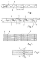
- Each wedge half has a multiplicity of wedge surfaces 3, 4 which lie against one another in pairs. In the example, 5 partial wedge surfaces are provided per wedge half.
- Each of these "partial wedges” has a wedge angle ⁇ which is five times larger than a conventional wedge with a continuous wedge surface. With n “partial wedges” the wedge angle would be n times larger.
- the length of a partial wedge surface 3, 4 and the wedge angle ⁇ are dimensioned such that the maximum width b of the wedge is reached when the two wedge halves are shifted by half the partial wedge length e0.
- the wedge halves 1, 2 can be worked out of solid. However, it is more economical to build up the wedge halves from many individual sheets 5 stacked one on top of the other, which are offset in places (FIG. 3). These single sheets can be made with the necessary precision, e.g. from waste, punch out. Through holes 6 can be produced at the same time, which are aligned with one another in the stack of sheets and thus penetrate the entire stack.
- the stacks are then e.g. riveted together.
- a simplification of the joining of the individual sheets can be achieved in that, according to FIG. 4, in each partial sheet 5 on one side a depression 7 and on the other side of the partial sheet coaxially to the depression 7, a projection 8 is attached, the inner diameter d 1 of the depression 7 is a little smaller than the outer diameter d2 of the projection 8.
- the attachment of the recess 7 and the projection 8 can be done in a single operation, preferably when punching the partial sheets 5, with a stamp with the outer diameter d1 and a die with a recess with the inner diameter d2.
- the projections 8 are pressed into the depressions 7 and thus ensure that the stack is held together.
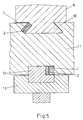
- a pole 9 with a dovetail pole claw 10 is arranged in an axially extending groove in the rotor ring 11 of a hydraulic machine. Between the one groove wall and the claw 10, the double inclined wedge consisting of the wedge halves 1, 2 is inserted. By mutual axial displacement of the two wedge halves, the pole 9 and the rotor ring 11 are clamped together.
- the rotor ring 11 is fastened to the outer circumference of the wheel spider 13 via axially extending rectangular bars 12, a double oblique wedge with the wedge halves 1, 2 causing tangential wedging in a rectangular, axially extending recess in the rectangular bar 12.
Landscapes
- Engineering & Computer Science (AREA)
- General Engineering & Computer Science (AREA)
- Power Engineering (AREA)
- Mechanical Engineering (AREA)
- Iron Core Of Rotating Electric Machines (AREA)
- Insulation, Fastening Of Motor, Generator Windings (AREA)
- Clamps And Clips (AREA)
- Organic Low-Molecular-Weight Compounds And Preparation Thereof (AREA)
- Polishing Bodies And Polishing Tools (AREA)
- Diaphragms For Electromechanical Transducers (AREA)
- Devices For Conveying Motion By Means Of Endless Flexible Members (AREA)
- Magnetic Heads (AREA)
- Control Of The Air-Fuel Ratio Of Carburetors (AREA)
Description
- Die Erfindung bezieht sich auf einen Doppelschrägkeil, insbesondere zur Pol- und Rotorringbefestigung von elektrischen Maschinen, bestehend aus zwei gleichartigen Keilhälften, die an ihren Keilflächen in Keillängssrichtung verschiebbar sind und bei Relativbewegungen zueinander die Breite des Keils in Querrichtung veränderbar ist.
- Doppelschrägkeile dieser Art werden insbesondere zum Verspannen der Pole auf dem Rotorring und des Rotorrings auf dem Radstern von Synchronmaschinen verwendet (vgl. Wiedemann/Kellerberger "Konstruktion elektrischer Maschinen", Springer-Verlag Berlin/Heidelberg/New York 1967, S. 370, Abb. 367b). Sie bestehen aus zwei Keilhälften, deren axiale Länge (typisch bis 2,5 m ) derjenigen des Pols entspricht. Der Keilwinkel ist - gemessen an üblichen Keilen - sehr klein.
- Die Herstellung von Keilen dieser Länge ist vergleichsweise aufwendig. Ihre Montage ist einfach, doch das Entfernen der Keile ist ohne Beschädigung der Keile und deren Sitzfläche praktisch nicht möglich.
- In dem Dokument DE-A-2 352 048 ist ein Keil beschrieben, der aus zwei äusseren Teilen und einem dazwischen gleitend angeordnetem dritten Teil besteht. Das eine äussere und das dazwischenliegende Teil sind mit mehreren zusammenwirkenden Teilkeilfächen versehen. Hierbei handelt es sich um einen auf Baustellen benötigten Gegenstand, der dahingehend verbessert wurde, dass er leicht von einer festgeklemmten Lage befreit werden kann. Dieser bekannte Keil ist demgemäss nicht dazu vorgesehen, Maschinenteile dauerhaft miteinander zu verbinden.
- Aufgabe der vorliegenden Erfindung ist es, einen Doppelschrägkeil anzugeben, der wirtschaftlich herzustellen ist und dessen Montage und Demontage leicht möglich ist.
- Diese Aufgabe wird bei einem Doppelschrägkeil der eingangs genannten Gattung erfindungsgemäss dadurch gelöst,
dass die Keilflächen auf eine Vielzahl unter sich kongruenter Teilkeilflächen verteilt sind, die für jede Keilhälfte jeweils zumindest abschnittsweise einstückig miteinander verbunden sind, wobei sich die ergebende wirksame Breite b des Doppelschrägkeils bei Verschiebung um die Länge l aus der Beziehung

ergibt, worin b₀ die Anfangsbreite des Keils und α den Keilwinkel eines Teilkeils bedeuten. - Ein derart ausgebildeter Keil ist einfach zu fertigen, insbesondere wenn er aus einzelnen ausgestanzten Blechen zusammengesetzt ist.
- Bezüglich Montage ist er ebenso problemlos einzubauen wie der bekannte Doppelschrägkeil. Bei der Demontage löst sich der Keil nach einer wesentlich kürzeren Austreibstrecke.
- Die Erfindung wird nachstehend anhand eines Ausführungsbeispiels näher erläutert. In der Zeichnung zeigt
- Fig. 1
- eine Draufsicht auf einen Doppelschrägkeil in der Grundstellung;
- Fig. 2
- eine Draufsicht auf den Keil nach Fig. 1 mit gegeneinander verschobenen Keilhälften;
- Fig. 3
- eine Seitenansicht des Keils nach Fig. 1;
- Fig. 4
- einen Schnitt durch eine Blechlage in vergrössertem Massstab;
- Fig. 5
- einen stark vereinfachten Schnitt durch den Rotorkranz eines Hydrogenerators.
- Der Doppelschrägkeil gemäss Fig. 1 besteht aus zwei Keilhälften 1 und 2. Jede Keilhälfte weist eine Vielzahl von Keilflächen 3,4 auf, die paarweise aneinanderliegen. Im Beispielsfall sind 5 Teilkeilflächen je Keilhälfte vorgesehen. Jeder dieser "Teilkeile" weist einen Keilwinkel α auf, der fünfmal grösser ist als ein üblicher Keil mit einer durchgehenden Keilfläche. Bei n "Teilkeilen" wäre der Keilwinkel n mal grösser.
- Die Länge einer Teilkeilfläche 3,4 und der Keilwinkel α sind so bemessen, dass bei Verschiebung beider Keilhälften um die halbe Teilkeillänge e₀ die maximale Breite b des Keils erreicht ist.
- Grundsätzlich können die Keilhälften 1,2 aus dem Vollen herausgearbeitet werden. Wirtschaftlicher ist es jedoch, die Keilhälften aus vielen übereinandergestapelten Einzelblechen 5, die lageweise versetzt sind, aufzubauen (Fig. 3). Diese Einzelbleche lassen sich mit der notwendigen Präzision, z.B. aus Abfall, ausstanzen. Dabei können gleichzeitig Durchgangsbohrungen 6 hergestellt werden, die im Blechstapel miteinander fluchten und so den gesamten Stapel durchdringen.
- Allgemein ergibt sich die wirksame Breite b des Doppelschrägkeils bei Verschiebung um die Länge l aus der Beziehung

worin b₀ die Anfangsbreite des Keils und α den Keilwinkel eines Teilkeils bedeuten. - Die Stapel werden dann z.B. miteinander vernietet.
- Eine Vereinfachung des Zusammenfügens der Einzelbleche lässt sich dadurch erzielen, dass entsprechend Fig. 4 in jedes Teilblech 5 auf der einen Seite eine Vertiefung 7 und auf der anderen Seite des Teilblechs koaxial zur Vertiefung 7 ein Vorsprung 8 angebracht wird, wobei der Innendurchmesser d₁ der Vertiefung 7 ein wenig kleiner ist als der Aussendurchmesser d₂ des Vorsprungs 8. Das Anbringen der Vertiefung 7 und des Vorsprungs 8 kann in einem einzigen Arbeitsvorgang, vorzugsweise beim Stanzen der Teilbleche 5, erfolgen, mit einem Stempel mit dem Aussendurchmesser d₁ und einer Matrize mit einer Vertiefung mit dem Innendurchmesser d₂.
- Beim Zusammenpressen des Stapels werden die Vorsprünge 8 in die Vertiefungen 7 gepresst und stellen somit den Zusammenhalt des Stapels sicher.
- In Fig. 5 ist in vereinfachter Darstellung der bevorzugte Einsatz der erfindungsgemässen Doppelschrägkeile veranschaulicht.
- In der oberen Hälfte ist ein Pol 9 mit schwalbenschwanzförmiger Polklaue 10 in einer axial verlaufenden Nut im Rotorring 11 einer Hydromaschine angeordnet. Zwischen der einen Nutwandung und der Klaue 10 ist der aus den Keilhälften 1,2 bestehende Doppelschrägkeil eingelegt. Durch gegenseitige axiale Verschiebung beider Keilhälften sind Pol 9 und Rotorring 11 miteinander verspannt.
- In der unteren Hälfte der Fig. 5 ist der Rotorring 11 über axial verlaufende Recheckleisten 12 am Aussenumfang des Radsterns 13 befestigt, wobei in einer rechteckförmigen, axial verlaufenden Ausnehmung in der Rechteckleiste 12 ein Doppelschrägkeil mit den Keilhälften 1,2 eine Tangentialverkeilung bewirkt.
Claims (4)
- Doppelschrägkeil, insbesondere zur Pol- und Rotorringbefestigung von elektrischen Maschinen, bestehend aus zwei gleichartigen Keilhälften (1,2), die an ihren Keilflächen (3,4) in Keillängsrichtung verschiebbar sind und bei Relativbewegung zueinander die wirksame Breite des Keils in Querrichtung veränderbar ist, dadurch gekennzeichnet, dass die Keilflächen auf eine Vielzahl unter sich kongruenter Teilkeilflächen (3,4) verteilt sind, die für jede Keilhälfte (1,2) jeweils zumindest abschnittsweise einstückig miteinander verbunden sind, wobei sich die ergebende wirksame Breite b des Doppelschrägkeils bei Verschiebung um die Länge l aus der Beziehung

ergibt, worin b₀ die Anfangsbreite des Keils und α den Keilwinkel eines Teilkeils bedeuten. - Doppelschrägkeil nach Anspruch 1, dadurch gekennzeichnet, dass die Keilhälften (3,4) aus miteinander verbundenen Einzelblechen (5) bestehen (Fig. 3).
- Doppelschrägkeil nach Anspruch 2, dadurch gekennzeichnet, dass die Einzelbleche 5 auf einer Seite mit Vertiefungen (7) und auf der anderen Seite mit an die Vertiefungen angepassten Vorsprüngen (8) versehen sind.
- Doppelschrägkeil nach Anspruch 1 oder 2, dadurch gekennzeichnet, dass die Länge der Einzelbleche kleiner als die Gesamtlänge des Keils ist und diese im Stapel lagenweise gegeneinander versetzt sind.
Priority Applications (1)
| Application Number | Priority Date | Filing Date | Title |
|---|---|---|---|
| AT89102749T ATE89106T1 (de) | 1988-03-21 | 1989-02-17 | Doppelschraegkeil. |
Applications Claiming Priority (2)
| Application Number | Priority Date | Filing Date | Title |
|---|---|---|---|
| CH1060/88A CH675280A5 (de) | 1988-03-21 | 1988-03-21 | |
| CH1060/88 | 1988-03-21 |
Publications (2)
| Publication Number | Publication Date |
|---|---|
| EP0334020A1 EP0334020A1 (de) | 1989-09-27 |
| EP0334020B1 true EP0334020B1 (de) | 1993-05-05 |
Family
ID=4201509
Family Applications (1)
| Application Number | Title | Priority Date | Filing Date |
|---|---|---|---|
| EP89102749A Expired - Lifetime EP0334020B1 (de) | 1988-03-21 | 1989-02-17 | Doppelschrägkeil |
Country Status (12)
| Country | Link |
|---|---|
| EP (1) | EP0334020B1 (de) |
| JP (1) | JPH01283415A (de) |
| CN (1) | CN1011372B (de) |
| AT (1) | ATE89106T1 (de) |
| BR (1) | BR8901278A (de) |
| CA (1) | CA1311515C (de) |
| CH (1) | CH675280A5 (de) |
| CS (1) | CS170589A3 (de) |
| DE (1) | DE58904242D1 (de) |
| ES (1) | ES2040911T3 (de) |
| RU (1) | RU1789053C (de) |
| YU (1) | YU56189A (de) |
Families Citing this family (4)
| Publication number | Priority date | Publication date | Assignee | Title |
|---|---|---|---|---|
| US5952755A (en) * | 1997-03-18 | 1999-09-14 | Electric Boat Corporation | Permanent magnet motor rotor |
| JP4462762B2 (ja) * | 1998-07-14 | 2010-05-12 | 株式会社横田製作所 | 組合わせ部材 |
| EP1315270A1 (de) * | 2001-11-22 | 2003-05-28 | ALSTOM (Switzerland) Ltd | Polrad |
| KR100617250B1 (ko) * | 2003-04-29 | 2006-08-29 | 박종원 | 건축·토목용 판상강재 또는 형강재 접합장치 |
Family Cites Families (2)
| Publication number | Priority date | Publication date | Assignee | Title |
|---|---|---|---|---|
| DE974711C (de) * | 1950-06-02 | 1961-04-06 | Siemens Ag | Aus einzelnen Blechsegmenten aufgebauter Jochring fuer den umlaufenden Erregerteil grosser Generatoren |
| US2870357A (en) * | 1955-11-30 | 1959-01-20 | Allis Chalmers Mfg Co | Dynamoelectric machine |
-
1988
- 1988-03-21 CH CH1060/88A patent/CH675280A5/de not_active IP Right Cessation
-
1989
- 1989-02-17 EP EP89102749A patent/EP0334020B1/de not_active Expired - Lifetime
- 1989-02-17 ES ES198989102749T patent/ES2040911T3/es not_active Expired - Lifetime
- 1989-02-17 DE DE8989102749T patent/DE58904242D1/de not_active Expired - Lifetime
- 1989-02-17 AT AT89102749T patent/ATE89106T1/de not_active IP Right Cessation
- 1989-03-08 CA CA000593076A patent/CA1311515C/en not_active Expired - Lifetime
- 1989-03-20 CS CS891705A patent/CS170589A3/cs unknown
- 1989-03-20 RU SU4613706A patent/RU1789053C/ru active
- 1989-03-20 BR BR898901278A patent/BR8901278A/pt not_active IP Right Cessation
- 1989-03-20 JP JP1066492A patent/JPH01283415A/ja active Pending
- 1989-03-20 YU YU00561/89A patent/YU56189A/xx unknown
- 1989-03-21 CN CN89101755A patent/CN1011372B/zh not_active Expired
Also Published As
| Publication number | Publication date |
|---|---|
| ES2040911T3 (es) | 1993-11-01 |
| RU1789053C (ru) | 1993-01-15 |
| CH675280A5 (de) | 1990-09-14 |
| CN1036106A (zh) | 1989-10-04 |
| CN1011372B (zh) | 1991-01-23 |
| DE58904242D1 (de) | 1993-06-09 |
| BR8901278A (pt) | 1989-11-07 |
| CS170589A3 (en) | 1992-12-16 |
| EP0334020A1 (de) | 1989-09-27 |
| YU56189A (en) | 1991-06-30 |
| ATE89106T1 (de) | 1993-05-15 |
| JPH01283415A (ja) | 1989-11-15 |
| CA1311515C (en) | 1992-12-15 |
Similar Documents
| Publication | Publication Date | Title |
|---|---|---|
| DE10009151C2 (de) | Magnethalterung bzw. Verfahren zur Halterung eines Magneten auf einem Trägerelement | |
| DE2342422C3 (de) | Walzenmantel | |
| EP0286905A1 (de) | Elektronisch kommutierter, kollektorloser Gleichstrommotor | |
| DE102009057782A1 (de) | Stator für rotierende elektrische Maschine | |
| EP2499718A1 (de) | Rotor einer elektrischen maschine | |
| EP3676939B1 (de) | Halterung von stator im gehäuse durch federelemente | |
| EP0334020B1 (de) | Doppelschrägkeil | |
| EP3479459B1 (de) | Rotor mit rotorschrägung für eine elektrische maschine und elektromotor für den fahrantrieb eines kraftfahrzeugs | |
| DE102004008936A1 (de) | Anker für einen Gleichstrommotor | |
| WO2008119660A2 (de) | Rotor für eine elektrodynamische maschine | |
| DE102009001035A1 (de) | Rotoranordnung für einen Elektromotor | |
| DE10051386A1 (de) | Reluktanzmotor mit einem geweiteten Boden | |
| DE3223994C2 (de) | Axialsicherungselement | |
| DE4127787A1 (de) | Kernstruktur eines rotors bei einer elektromagnetischen maschine | |
| DE4222187C1 (en) | Squirrel cage rotor with short-circuit cage on endface of laminated core - has bars arranged in grooves of laminated core and connected to short-circuit rings | |
| DE102022125718A1 (de) | Elektromotorvorrichtung mit mehrstufig geschränkt angeordneten Rotorblechen sowie entsprechend ausgestatteter Rotor und dessen Verwendung insbesondere in Aufzugsanlagen | |
| EP0950027A1 (de) | Scheibentauchkörper | |
| EP0817355A2 (de) | Selbsttragendes, mit Permanentmagneten bestücktes Läuferblechpaket | |
| DE2118126A1 (de) | Zahnrad, insbesondere für Synchrongetriebe | |
| DE102019213574A1 (de) | Rotor einer elektrischen Maschine | |
| EP1315270A1 (de) | Polrad | |
| DE1184411B (de) | Befestigung der ausgepraegten Pole am Laeufer elektrischer Maschinen an einem kammartig mit Rillen versehenen Jochring | |
| DE102019119536A1 (de) | Stator für eine elektrische Maschine sowie entsprechende elektrische Maschine | |
| DE4020321C1 (en) | Milling cutter with detachable cutting tools - has each tool bolted to cassette with U=shaped foot engaging hub ring | |
| DE2314176C2 (de) | Offener, elastischer Klemmring zum Einsatz insbesondere in der Abwassertechnik |
Legal Events
| Date | Code | Title | Description |
|---|---|---|---|
| PUAI | Public reference made under article 153(3) epc to a published international application that has entered the european phase |
Free format text: ORIGINAL CODE: 0009012 |
|
| AK | Designated contracting states |
Kind code of ref document: A1 Designated state(s): AT CH DE ES FR GB IT LI |
|
| 17P | Request for examination filed |
Effective date: 19900228 |
|
| 17Q | First examination report despatched |
Effective date: 19920225 |
|
| GRAA | (expected) grant |
Free format text: ORIGINAL CODE: 0009210 |
|
| AK | Designated contracting states |
Kind code of ref document: B1 Designated state(s): AT CH DE ES FR GB IT LI |
|
| REF | Corresponds to: |
Ref document number: 89106 Country of ref document: AT Date of ref document: 19930515 Kind code of ref document: T |
|
| REF | Corresponds to: |
Ref document number: 58904242 Country of ref document: DE Date of ref document: 19930609 |
|
| ITF | It: translation for a ep patent filed | ||
| GBT | Gb: translation of ep patent filed (gb section 77(6)(a)/1977) |
Effective date: 19930714 |
|
| ET | Fr: translation filed | ||
| REG | Reference to a national code |
Ref country code: ES Ref legal event code: FG2A Ref document number: 2040911 Country of ref document: ES Kind code of ref document: T3 |
|
| PLBE | No opposition filed within time limit |
Free format text: ORIGINAL CODE: 0009261 |
|
| STAA | Information on the status of an ep patent application or granted ep patent |
Free format text: STATUS: NO OPPOSITION FILED WITHIN TIME LIMIT |
|
| 26N | No opposition filed | ||
| REG | Reference to a national code |
Ref country code: GB Ref legal event code: IF02 |
|
| REG | Reference to a national code |
Ref country code: CH Ref legal event code: PUE Owner name: ASEA BROWN BOVERI AG TRANSFER- ALSTOM Ref country code: CH Ref legal event code: NV Representative=s name: GIACOMO BOLIS C/O ALSTOM (SWITZERLAND) LTD CHSP IN |
|
| REG | Reference to a national code |
Ref country code: GB Ref legal event code: 732E |
|
| REG | Reference to a national code |
Ref country code: FR Ref legal event code: CA Ref country code: FR Ref legal event code: CD |
|
| REG | Reference to a national code |
Ref country code: FR Ref legal event code: TP |
|
| PGFP | Annual fee paid to national office [announced via postgrant information from national office to epo] |
Ref country code: ES Payment date: 20080228 Year of fee payment: 20 Ref country code: CH Payment date: 20080215 Year of fee payment: 20 |
|
| PGFP | Annual fee paid to national office [announced via postgrant information from national office to epo] |
Ref country code: DE Payment date: 20080219 Year of fee payment: 20 Ref country code: IT Payment date: 20080220 Year of fee payment: 20 Ref country code: GB Payment date: 20080220 Year of fee payment: 20 |
|
| PGFP | Annual fee paid to national office [announced via postgrant information from national office to epo] |
Ref country code: AT Payment date: 20080215 Year of fee payment: 20 |
|
| PGFP | Annual fee paid to national office [announced via postgrant information from national office to epo] |
Ref country code: FR Payment date: 20080214 Year of fee payment: 20 |
|
| REG | Reference to a national code |
Ref country code: CH Ref legal event code: PL |
|
| REG | Reference to a national code |
Ref country code: GB Ref legal event code: PE20 Expiry date: 20090216 |
|
| REG | Reference to a national code |
Ref country code: ES Ref legal event code: FD2A Effective date: 20090218 |
|
| PG25 | Lapsed in a contracting state [announced via postgrant information from national office to epo] |
Ref country code: GB Free format text: LAPSE BECAUSE OF EXPIRATION OF PROTECTION Effective date: 20090216 |
|
| PG25 | Lapsed in a contracting state [announced via postgrant information from national office to epo] |
Ref country code: ES Free format text: LAPSE BECAUSE OF EXPIRATION OF PROTECTION Effective date: 20090218 |