EP0334012A2 - Embout de fil - Google Patents
Embout de fil Download PDFInfo
- Publication number
- EP0334012A2 EP0334012A2 EP89102465A EP89102465A EP0334012A2 EP 0334012 A2 EP0334012 A2 EP 0334012A2 EP 89102465 A EP89102465 A EP 89102465A EP 89102465 A EP89102465 A EP 89102465A EP 0334012 A2 EP0334012 A2 EP 0334012A2
- Authority
- EP
- European Patent Office
- Prior art keywords
- wire end
- end sleeve
- bead
- sleeve
- wire
- Prior art date
- Legal status (The legal status is an assumption and is not a legal conclusion. Google has not performed a legal analysis and makes no representation as to the accuracy of the status listed.)
- Withdrawn
Links
- 239000011324 bead Substances 0.000 claims abstract description 20
- 238000002788 crimping Methods 0.000 claims description 12
- 238000005096 rolling process Methods 0.000 claims description 4
- 239000004020 conductor Substances 0.000 claims description 2
- 239000002184 metal Substances 0.000 description 5
- 241000251730 Chondrichthyes Species 0.000 description 2
- 238000000034 method Methods 0.000 description 2
- 230000015572 biosynthetic process Effects 0.000 description 1
- 238000003780 insertion Methods 0.000 description 1
- 230000037431 insertion Effects 0.000 description 1
Images
Classifications
-
- H—ELECTRICITY
- H01—ELECTRIC ELEMENTS
- H01R—ELECTRICALLY-CONDUCTIVE CONNECTIONS; STRUCTURAL ASSOCIATIONS OF A PLURALITY OF MUTUALLY-INSULATED ELECTRICAL CONNECTING ELEMENTS; COUPLING DEVICES; CURRENT COLLECTORS
- H01R11/00—Individual connecting elements providing two or more spaced connecting locations for conductive members which are, or may be, thereby interconnected, e.g. end pieces for wires or cables supported by the wire or cable and having means for facilitating electrical connection to some other wire, terminal, or conductive member, blocks of binding posts
- H01R11/11—End pieces or tapping pieces for wires, supported by the wire and for facilitating electrical connection to some other wire, terminal or conductive member
-
- H—ELECTRICITY
- H01—ELECTRIC ELEMENTS
- H01R—ELECTRICALLY-CONDUCTIVE CONNECTIONS; STRUCTURAL ASSOCIATIONS OF A PLURALITY OF MUTUALLY-INSULATED ELECTRICAL CONNECTING ELEMENTS; COUPLING DEVICES; CURRENT COLLECTORS
- H01R2103/00—Two poles
-
- H—ELECTRICITY
- H01—ELECTRIC ELEMENTS
- H01R—ELECTRICALLY-CONDUCTIVE CONNECTIONS; STRUCTURAL ASSOCIATIONS OF A PLURALITY OF MUTUALLY-INSULATED ELECTRICAL CONNECTING ELEMENTS; COUPLING DEVICES; CURRENT COLLECTORS
- H01R24/00—Two-part coupling devices, or either of their cooperating parts, characterised by their overall structure
- H01R24/58—Contacts spaced along longitudinal axis of engagement
-
- H—ELECTRICITY
- H01—ELECTRIC ELEMENTS
- H01R—ELECTRICALLY-CONDUCTIVE CONNECTIONS; STRUCTURAL ASSOCIATIONS OF A PLURALITY OF MUTUALLY-INSULATED ELECTRICAL CONNECTING ELEMENTS; COUPLING DEVICES; CURRENT COLLECTORS
- H01R4/00—Electrically-conductive connections between two or more conductive members in direct contact, i.e. touching one another; Means for effecting or maintaining such contact; Electrically-conductive connections having two or more spaced connecting locations for conductors and using contact members penetrating insulation
- H01R4/28—Clamped connections, spring connections
- H01R4/48—Clamped connections, spring connections utilising a spring, clip, or other resilient member
- H01R4/4809—Clamped connections, spring connections utilising a spring, clip, or other resilient member using a leaf spring to bias the conductor toward the busbar
- H01R4/48185—Clamped connections, spring connections utilising a spring, clip, or other resilient member using a leaf spring to bias the conductor toward the busbar adapted for axial insertion of a wire end
- H01R4/4819—Clamped connections, spring connections utilising a spring, clip, or other resilient member using a leaf spring to bias the conductor toward the busbar adapted for axial insertion of a wire end the spring shape allowing insertion of the conductor end when the spring is unbiased
- H01R4/4821—Single-blade spring
Definitions
- the invention relates to a wire end sleeve for the stripped wire end of an electrical cable made of an electrically conductive material for making electrical contact with the wire end in an electrical connector having an electrical contact spring.
- End sleeves are known. They are attached to the stripped wire end of an electrical cable and are intended to prevent the individual wires of a multi-wire wire from spreading out by the wire end sleeve enclosing these wires in a sleeve-like manner.
- a known wire end sleeve consists of a V-shaped metal part before being attached to the wire end, which is crimped onto the stripped wire end of the electrical cable by rolling using a crimping tool.
- the legs of the V-shaped metal part have teeth (so-called shark teeth) which, after crimping, onto the Interlocking wire ends.
- wire ends of an electrical cable provided with wire end sleeves can be contacted, for example, in electrical sockets (for example lamp sockets, terminal blocks, etc.) by inserting the wire ends with their wire end sleeves into the socket, an electrical contact spring of the socket being resilient on the outside of the wire end sleeve comes to rest and thereby fixes the wire end within the socket and thereby the makes electrical contact.
- electrical sockets for example lamp sockets, terminal blocks, etc.
- an electrical contact spring of the socket being resilient on the outside of the wire end sleeve comes to rest and thereby fixes the wire end within the socket and thereby the makes electrical contact.
- the disadvantage here is that the wire end is not securely fixed in the socket, since the wire end of the electrical cable can be pulled out of the socket by already low pull-out forces due to the relatively smooth surface of the wire end sleeve, without the wire end sleeve counteracting this to a sufficient extent. This is especially true when the smooth and not the top of the wire end sleeve, which is interrupted by the
- the object of the invention is to further develop the known wire end sleeve in such a way that a wire end of an electrical cable provided with it can be securely fixed in an electrical plug connection.
- the invention proposes that the wire end sleeve has at least one bead into which the contact spring snaps into the electrical connector after the wire end has been inserted.
- Such a bead formed on the circumference of the wire end sleeve has the advantage that the contact spring of the plug connection can snap into it, which increases the pull-out forces when the wire end of the electrical cable is pulled out of the plug connection. Overall, the wire end of the electrical cable is thus better fixed in the plug connection.
- the bead In a further development of the bead, it is proposed that it surrounds the wire end sleeve essentially concentrically to its longitudinal axis. This has the advantage that in everyone (Angle of rotation) position of the wire end and thus the wire end sleeve, the contact spring of the plug connection can engage in the bead and thus secure fixation within the plug connection is ensured in every position of the wire end.
- the bead is formed on the wire end sleeve on the side opposite the toothing. This has the advantage that on one side of the wire end sleeve the toothing fulfills a certain latching function, while on the opposite side, where the wire end sleeve is normally completely smooth, the bead is responsible for the snap-in of the contact spring.
- the bead is stamped into the wire end sleeve during the crimping onto the wire end by means of the crimping tool.
- the formation of the bead can thus be accomplished in a simple manner during the crimping of the wire end sleeve onto the wire end, without the need for an additional operation. It is only necessary to emboss the bead in the wire end sleeve in the lifting machine without changing the V-shaped metal part of the wire end sleeve by simply modifying the lower punch and / or the upper punch.
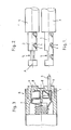
- the first embodiment of a wire end sleeve 1 shown in FIG. 1 is fastened on the stripped wire end 2 of an electrical cable 3.
- the wire end sleeve 1 is crimped onto the wire end 2 by means of a corresponding crimping tool (attachment machine or hand tool).
- a V-shaped metal part is assumed, into which the wire end 2 of the electrical cable 3 is placed.
- its legs have so-called shark teeth, which engage during crimping and form a toothing 4, as can be seen in FIG. 1.
- the wire end sleeve 1 has a bead 5 on the side opposite the toothing 4. This can be stamped into the wire end sleeve 1 during the crimping process using the corresponding crimping tool.
- FIG. 2 shows a second embodiment of a wire end sleeve 1.
- the only difference to that shown in Fig. 1 presented first embodiment consists only in that the bead 5 completely surrounds the ferrule 1, namely concentrically to the longitudinal axis A.
- a connector is shown as a socket 6 in the form of a lamp socket.
- two contact springs 8 are arranged in a housing 7, the ends of which are designed to be elastic.
- the housing 7 is provided with two openings 9, through which the wire ends 2 of an electrical cable 3 fitted with wire end sleeves 1 can be inserted and contacted by the contact springs 8.
- Fig. 3 it is only shown how an electrical cable 3 is inserted through the lower opening 9, which is provided with an end sleeve 1 of the embodiment shown in Fig. 1.
- Fig. 3 it is only shown how an electrical cable 3 is inserted through the lower opening 9, which is provided with an end sleeve 1 of the embodiment shown in Fig. 1.
Landscapes
- Connections Effected By Soldering, Adhesion, Or Permanent Deformation (AREA)
- Manufacturing Of Electrical Connectors (AREA)
- Processing Of Terminals (AREA)
Applications Claiming Priority (2)
| Application Number | Priority Date | Filing Date | Title |
|---|---|---|---|
| DE3809322 | 1988-03-19 | ||
| DE3809322A DE3809322A1 (de) | 1988-03-19 | 1988-03-19 | Aderendhuelse |
Publications (2)
| Publication Number | Publication Date |
|---|---|
| EP0334012A2 true EP0334012A2 (fr) | 1989-09-27 |
| EP0334012A3 EP0334012A3 (fr) | 1990-09-12 |
Family
ID=6350205
Family Applications (1)
| Application Number | Title | Priority Date | Filing Date |
|---|---|---|---|
| EP19890102465 Withdrawn EP0334012A3 (fr) | 1988-03-19 | 1989-02-14 | Embout de fil |
Country Status (3)
| Country | Link |
|---|---|
| EP (1) | EP0334012A3 (fr) |
| DE (1) | DE3809322A1 (fr) |
| HU (1) | HUT49424A (fr) |
Cited By (2)
| Publication number | Priority date | Publication date | Assignee | Title |
|---|---|---|---|---|
| GB2267606A (en) * | 1992-05-28 | 1993-12-08 | Electrolux Northern | Electrical contact. |
| DE102020110108A1 (de) | 2020-04-09 | 2021-10-14 | Tesona Gmbh & Co. Kg | Temperatursensor, insbesondere für automobile Anwendungen |
Family Cites Families (9)
| Publication number | Priority date | Publication date | Assignee | Title |
|---|---|---|---|---|
| DE1065909B (fr) * | 1959-09-24 | |||
| US2234820A (en) * | 1935-08-23 | 1941-03-11 | Kingston Products Corp | Electrical contact means |
| US3140142A (en) * | 1961-11-07 | 1964-07-07 | Ibm | Electrical connector |
| US3787800A (en) * | 1963-10-11 | 1974-01-22 | Eltra Corp | Resistor ignition lead |
| US3493917A (en) * | 1967-08-01 | 1970-02-03 | Viking Industries | Connector locking means |
| US3813643A (en) * | 1971-10-28 | 1974-05-28 | Essex International Inc | Terminating of electrical conductors |
| AT365003B (de) * | 1979-05-02 | 1981-12-10 | Neutrik Ag | Kontaktbuchse zur aufnahme eines kontaktstiftes fuer elektrische kontakte |
| DE3105429A1 (de) * | 1981-02-14 | 1982-10-28 | Grote & Hartmann Gmbh & Co Kg, 5600 Wuppertal | "zusatzverriegelung in einem verbindergehaeuse fuer einen elektrischen verbinder" |
| FR2579836B1 (fr) * | 1985-03-27 | 1987-10-16 | Telemecanique Electrique | Embout pour conducteur electrique et son procede de fabrication |
-
1988
- 1988-03-19 DE DE3809322A patent/DE3809322A1/de not_active Withdrawn
-
1989
- 1989-02-14 EP EP19890102465 patent/EP0334012A3/fr not_active Withdrawn
- 1989-03-17 HU HU891270A patent/HUT49424A/hu unknown
Cited By (3)
| Publication number | Priority date | Publication date | Assignee | Title |
|---|---|---|---|---|
| GB2267606A (en) * | 1992-05-28 | 1993-12-08 | Electrolux Northern | Electrical contact. |
| DE102020110108A1 (de) | 2020-04-09 | 2021-10-14 | Tesona Gmbh & Co. Kg | Temperatursensor, insbesondere für automobile Anwendungen |
| DE102020110108B4 (de) | 2020-04-09 | 2024-07-25 | Tesona Gmbh & Co. Kg | Temperatursensor, insbesondere für automobile Anwendungen |
Also Published As
| Publication number | Publication date |
|---|---|
| EP0334012A3 (fr) | 1990-09-12 |
| DE3809322A1 (de) | 1989-09-28 |
| HUT49424A (en) | 1989-09-28 |
Similar Documents
| Publication | Publication Date | Title |
|---|---|---|
| DE2923399C2 (de) | Verfahren zur elektrischen Verbindung eines Koaxialkabels und Anschlußarmatur für Koaxialkabel | |
| DE19848344B4 (de) | Abgeschirmte Steckbuchse | |
| DE3587104T2 (de) | Elektrische steckervorrichtung. | |
| DE181305T1 (de) | Elektrische steckervorrichtung. | |
| DE102013106117B4 (de) | Steckverbinderanordnung und Steckverbindungssystem | |
| DE69116836T2 (de) | Zugentlastung für Schneidklemmkontaktelement | |
| DE2735838C2 (de) | Elektrische Anschlußklemme und elektrisches Kabelverbindungsglied | |
| DE69221428T2 (de) | Elektrische Kontaktbuchse | |
| EP2345110B1 (fr) | Connecteur enfichable pour câble à quartes en étoile | |
| DE10143851B4 (de) | Stecker mit Kontaktstift | |
| EP1467441A2 (fr) | Connecteur pour un branchement rapide à technique de pince de serrage | |
| EP0968548A1 (fr) | Douille munie de zones de contact a configuration hyperboloidale | |
| EP0319633B1 (fr) | Connecteur cinch | |
| EP0334012A2 (fr) | Embout de fil | |
| DE2517465C3 (de) | Steckverbinder | |
| DE2413445C2 (de) | Elektrischer Zwittersteckverbinder | |
| DE2539675A1 (de) | Jalousieartig aufgebauter verbinder und kontaktelemente fuer diesen | |
| DE4224155C2 (de) | Elektrische Steckverbinderanordnung | |
| DE102014116482A1 (de) | Kontaktelement | |
| DE19506713C2 (de) | Mehrpoliger Steckverbinder | |
| DE102005041922B4 (de) | Elektrische Steckverbindung mit federnden Brücken | |
| EP4231463B1 (fr) | Connecteur à monter sur une carte de circuit imprimé | |
| DE202005017981U1 (de) | Kontakthalterung für elektrische Steckverbinder | |
| DE2252145A1 (de) | Lampenhalter | |
| DE3314731C2 (de) | Steckkontaktbuchse |
Legal Events
| Date | Code | Title | Description |
|---|---|---|---|
| PUAI | Public reference made under article 153(3) epc to a published international application that has entered the european phase |
Free format text: ORIGINAL CODE: 0009012 |
|
| AK | Designated contracting states |
Kind code of ref document: A2 Designated state(s): DE ES FR GB IT |
|
| PUAL | Search report despatched |
Free format text: ORIGINAL CODE: 0009013 |
|
| AK | Designated contracting states |
Kind code of ref document: A3 Designated state(s): DE ES FR GB IT |
|
| STAA | Information on the status of an ep patent application or granted ep patent |
Free format text: STATUS: THE APPLICATION HAS BEEN WITHDRAWN |
|
| 18W | Application withdrawn |
Withdrawal date: 19900824 |
|
| R18W | Application withdrawn (corrected) |
Effective date: 19900824 |