EP0334012A2 - Wire end sleeve - Google Patents
Wire end sleeve Download PDFInfo
- Publication number
- EP0334012A2 EP0334012A2 EP89102465A EP89102465A EP0334012A2 EP 0334012 A2 EP0334012 A2 EP 0334012A2 EP 89102465 A EP89102465 A EP 89102465A EP 89102465 A EP89102465 A EP 89102465A EP 0334012 A2 EP0334012 A2 EP 0334012A2
- Authority
- EP
- European Patent Office
- Prior art keywords
- wire end
- end sleeve
- bead
- sleeve
- wire
- Prior art date
- Legal status (The legal status is an assumption and is not a legal conclusion. Google has not performed a legal analysis and makes no representation as to the accuracy of the status listed.)
- Withdrawn
Links
- 239000011324 bead Substances 0.000 claims abstract description 20
- 238000002788 crimping Methods 0.000 claims description 12
- 238000005096 rolling process Methods 0.000 claims description 4
- 239000004020 conductor Substances 0.000 claims description 2
- 239000002184 metal Substances 0.000 description 5
- 241000251730 Chondrichthyes Species 0.000 description 2
- 238000000034 method Methods 0.000 description 2
- 230000015572 biosynthetic process Effects 0.000 description 1
- 238000003780 insertion Methods 0.000 description 1
- 230000037431 insertion Effects 0.000 description 1
Images
Classifications
-
- H—ELECTRICITY
- H01—ELECTRIC ELEMENTS
- H01R—ELECTRICALLY-CONDUCTIVE CONNECTIONS; STRUCTURAL ASSOCIATIONS OF A PLURALITY OF MUTUALLY-INSULATED ELECTRICAL CONNECTING ELEMENTS; COUPLING DEVICES; CURRENT COLLECTORS
- H01R11/00—Individual connecting elements providing two or more spaced connecting locations for conductive members which are, or may be, thereby interconnected, e.g. end pieces for wires or cables supported by the wire or cable and having means for facilitating electrical connection to some other wire, terminal, or conductive member, blocks of binding posts
- H01R11/11—End pieces or tapping pieces for wires, supported by the wire and for facilitating electrical connection to some other wire, terminal or conductive member
-
- H—ELECTRICITY
- H01—ELECTRIC ELEMENTS
- H01R—ELECTRICALLY-CONDUCTIVE CONNECTIONS; STRUCTURAL ASSOCIATIONS OF A PLURALITY OF MUTUALLY-INSULATED ELECTRICAL CONNECTING ELEMENTS; COUPLING DEVICES; CURRENT COLLECTORS
- H01R2103/00—Two poles
-
- H—ELECTRICITY
- H01—ELECTRIC ELEMENTS
- H01R—ELECTRICALLY-CONDUCTIVE CONNECTIONS; STRUCTURAL ASSOCIATIONS OF A PLURALITY OF MUTUALLY-INSULATED ELECTRICAL CONNECTING ELEMENTS; COUPLING DEVICES; CURRENT COLLECTORS
- H01R24/00—Two-part coupling devices, or either of their cooperating parts, characterised by their overall structure
- H01R24/58—Contacts spaced along longitudinal axis of engagement
-
- H—ELECTRICITY
- H01—ELECTRIC ELEMENTS
- H01R—ELECTRICALLY-CONDUCTIVE CONNECTIONS; STRUCTURAL ASSOCIATIONS OF A PLURALITY OF MUTUALLY-INSULATED ELECTRICAL CONNECTING ELEMENTS; COUPLING DEVICES; CURRENT COLLECTORS
- H01R4/00—Electrically-conductive connections between two or more conductive members in direct contact, i.e. touching one another; Means for effecting or maintaining such contact; Electrically-conductive connections having two or more spaced connecting locations for conductors and using contact members penetrating insulation
- H01R4/28—Clamped connections, spring connections
- H01R4/48—Clamped connections, spring connections utilising a spring, clip, or other resilient member
- H01R4/4809—Clamped connections, spring connections utilising a spring, clip, or other resilient member using a leaf spring to bias the conductor toward the busbar
- H01R4/48185—Clamped connections, spring connections utilising a spring, clip, or other resilient member using a leaf spring to bias the conductor toward the busbar adapted for axial insertion of a wire end
- H01R4/4819—Clamped connections, spring connections utilising a spring, clip, or other resilient member using a leaf spring to bias the conductor toward the busbar adapted for axial insertion of a wire end the spring shape allowing insertion of the conductor end when the spring is unbiased
- H01R4/4821—Single-blade spring
Definitions
- the invention relates to a wire end sleeve for the stripped wire end of an electrical cable made of an electrically conductive material for making electrical contact with the wire end in an electrical connector having an electrical contact spring.
- End sleeves are known. They are attached to the stripped wire end of an electrical cable and are intended to prevent the individual wires of a multi-wire wire from spreading out by the wire end sleeve enclosing these wires in a sleeve-like manner.
- a known wire end sleeve consists of a V-shaped metal part before being attached to the wire end, which is crimped onto the stripped wire end of the electrical cable by rolling using a crimping tool.
- the legs of the V-shaped metal part have teeth (so-called shark teeth) which, after crimping, onto the Interlocking wire ends.
- wire ends of an electrical cable provided with wire end sleeves can be contacted, for example, in electrical sockets (for example lamp sockets, terminal blocks, etc.) by inserting the wire ends with their wire end sleeves into the socket, an electrical contact spring of the socket being resilient on the outside of the wire end sleeve comes to rest and thereby fixes the wire end within the socket and thereby the makes electrical contact.
- electrical sockets for example lamp sockets, terminal blocks, etc.
- an electrical contact spring of the socket being resilient on the outside of the wire end sleeve comes to rest and thereby fixes the wire end within the socket and thereby the makes electrical contact.
- the disadvantage here is that the wire end is not securely fixed in the socket, since the wire end of the electrical cable can be pulled out of the socket by already low pull-out forces due to the relatively smooth surface of the wire end sleeve, without the wire end sleeve counteracting this to a sufficient extent. This is especially true when the smooth and not the top of the wire end sleeve, which is interrupted by the
- the object of the invention is to further develop the known wire end sleeve in such a way that a wire end of an electrical cable provided with it can be securely fixed in an electrical plug connection.
- the invention proposes that the wire end sleeve has at least one bead into which the contact spring snaps into the electrical connector after the wire end has been inserted.
- Such a bead formed on the circumference of the wire end sleeve has the advantage that the contact spring of the plug connection can snap into it, which increases the pull-out forces when the wire end of the electrical cable is pulled out of the plug connection. Overall, the wire end of the electrical cable is thus better fixed in the plug connection.
- the bead In a further development of the bead, it is proposed that it surrounds the wire end sleeve essentially concentrically to its longitudinal axis. This has the advantage that in everyone (Angle of rotation) position of the wire end and thus the wire end sleeve, the contact spring of the plug connection can engage in the bead and thus secure fixation within the plug connection is ensured in every position of the wire end.
- the bead is formed on the wire end sleeve on the side opposite the toothing. This has the advantage that on one side of the wire end sleeve the toothing fulfills a certain latching function, while on the opposite side, where the wire end sleeve is normally completely smooth, the bead is responsible for the snap-in of the contact spring.
- the bead is stamped into the wire end sleeve during the crimping onto the wire end by means of the crimping tool.
- the formation of the bead can thus be accomplished in a simple manner during the crimping of the wire end sleeve onto the wire end, without the need for an additional operation. It is only necessary to emboss the bead in the wire end sleeve in the lifting machine without changing the V-shaped metal part of the wire end sleeve by simply modifying the lower punch and / or the upper punch.
- the first embodiment of a wire end sleeve 1 shown in FIG. 1 is fastened on the stripped wire end 2 of an electrical cable 3.
- the wire end sleeve 1 is crimped onto the wire end 2 by means of a corresponding crimping tool (attachment machine or hand tool).
- a V-shaped metal part is assumed, into which the wire end 2 of the electrical cable 3 is placed.
- its legs have so-called shark teeth, which engage during crimping and form a toothing 4, as can be seen in FIG. 1.
- the wire end sleeve 1 has a bead 5 on the side opposite the toothing 4. This can be stamped into the wire end sleeve 1 during the crimping process using the corresponding crimping tool.
- FIG. 2 shows a second embodiment of a wire end sleeve 1.
- the only difference to that shown in Fig. 1 presented first embodiment consists only in that the bead 5 completely surrounds the ferrule 1, namely concentrically to the longitudinal axis A.
- a connector is shown as a socket 6 in the form of a lamp socket.
- two contact springs 8 are arranged in a housing 7, the ends of which are designed to be elastic.
- the housing 7 is provided with two openings 9, through which the wire ends 2 of an electrical cable 3 fitted with wire end sleeves 1 can be inserted and contacted by the contact springs 8.
- Fig. 3 it is only shown how an electrical cable 3 is inserted through the lower opening 9, which is provided with an end sleeve 1 of the embodiment shown in Fig. 1.
- Fig. 3 it is only shown how an electrical cable 3 is inserted through the lower opening 9, which is provided with an end sleeve 1 of the embodiment shown in Fig. 1.
Landscapes
- Connections Effected By Soldering, Adhesion, Or Permanent Deformation (AREA)
- Manufacturing Of Electrical Connectors (AREA)
- Processing Of Terminals (AREA)
Abstract
Eine Aderendhülse 1 für das abisolierte Aderende 2 eines elektrischen Kabels 3 weist wenigstens eine Sicke 5 auf, in die die Kontaktfeder 8 einer Steckfassung 6 beim Einschieben des Aderendes 2 des elektrischen Kabels 3 einrastet. Dadurch werden die Auszugskräfte erhöht. 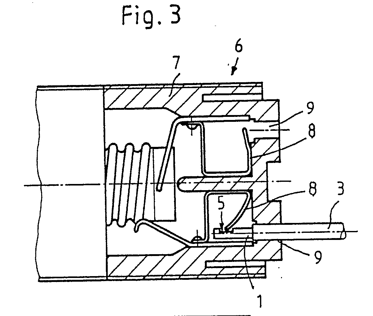
Description
Die Erfindung betrifft eine Aderendhülse für das abisolierte Aderende eines elektrischen Kabels aus einem elektrisch leitenden Material zum elektrischen Kontaktieren des Aderendes in einer eine elektrische Kontaktfeder aufweisenden elektrischen Steckverbindung.The invention relates to a wire end sleeve for the stripped wire end of an electrical cable made of an electrically conductive material for making electrical contact with the wire end in an electrical connector having an electrical contact spring.
Aderendhülsen sind bekannt. Sie werden auf dem abisolierten Aderende eines elektrischen Kabels befestigt und sollen dabei verhindern, daß sich die einzelnen Drähte einer mehrdrähtigen Ader aufspreizen, indem die Aderendhülse diese Drähte hülsenartig umschließt. Eine bekannte Aderendhülse besteht vor dem Befestigen auf dem Aderende aus einem V-förmigen Metallformteil, das durch Rollen mittels eines Crimpwerkzeuges auf das abisolierte Aderende des elektrischen Kabels aufgecrimpt wird. Um den Aufnahmekanal des V-förmigen Metallformteiles tief genug ausbilden zu können, damit sämtliche Drähte des mehrdrähtigen Aderendes darin vor dem Aufcrimpvorgang zu liegen kommen, weisen die Schenkel des V-förmigen Metallformteils eine Verzahnung (sogenannte Haifischzähne) auf, die nach dem Aufcrimpen auf das Aderende ineinandergreifen.End sleeves are known. They are attached to the stripped wire end of an electrical cable and are intended to prevent the individual wires of a multi-wire wire from spreading out by the wire end sleeve enclosing these wires in a sleeve-like manner. A known wire end sleeve consists of a V-shaped metal part before being attached to the wire end, which is crimped onto the stripped wire end of the electrical cable by rolling using a crimping tool. In order to be able to form the receiving channel of the V-shaped metal part deep enough so that all the wires of the multi-wire end of the wire lie in it before the crimping process, the legs of the V-shaped metal part have teeth (so-called shark teeth) which, after crimping, onto the Interlocking wire ends.
Die derart mit Aderendhülsen versehenen Aderenden eines elektrischen Kabels können beispielsweise in elektrischen Steckfassungen (beispielsweise Lampenfassungen, Reihenklemmen etc.) dadurch kontaktiert werden, indem die Aderenden mit ihren Aderendhülsen in die Steckfassung eingeschoben werden, wobei eine elektrische Kontaktfeder der Steckfassung an der Außenseite der Aderendhülse federnd zu liegen kommt und dadurch das Aderende innerhalb der Steckfassung fixiert und dabei den elektrischen Kontakt herstellt. Dabei ist von Nachteil, daß das Aderende nicht sicher in der Steckfassung festgelegt ist, da durch bereits geringe Ausziehkräfte aufgrund der relativ glatten Oberfläche der Aderendhülse das Aderende des elektrischen Kabels aus der Steckfassung herausgezogen werden kann, ohne daß die Aderendhülse dem in hinreichendem Maße entgegenwirkt. Dies gilt insbesondere dann, wenn die glatte und nicht die durch die Verzahnung unterbrochene Oberseite der Aderendhülse mit der Kontaktfeder der Steckfassung in Eingriff steht.The wire ends of an electrical cable provided with wire end sleeves can be contacted, for example, in electrical sockets (for example lamp sockets, terminal blocks, etc.) by inserting the wire ends with their wire end sleeves into the socket, an electrical contact spring of the socket being resilient on the outside of the wire end sleeve comes to rest and thereby fixes the wire end within the socket and thereby the makes electrical contact. The disadvantage here is that the wire end is not securely fixed in the socket, since the wire end of the electrical cable can be pulled out of the socket by already low pull-out forces due to the relatively smooth surface of the wire end sleeve, without the wire end sleeve counteracting this to a sufficient extent. This is especially true when the smooth and not the top of the wire end sleeve, which is interrupted by the toothing, engages with the contact spring of the jack.
Davon ausgehend liegt der Erfindung die Aufgabe zugrunde, die bekannte Aderendhülse derart weiterzuentwickeln, daß ein mit ihr versehenes Aderende eines elektrischen Kabels auf sichere Weise in einer elektrischen Steckverbindung festgelegt werden kann.Proceeding from this, the object of the invention is to further develop the known wire end sleeve in such a way that a wire end of an electrical cable provided with it can be securely fixed in an electrical plug connection.
Als technische Lösung wird mit der Erfindung vorgeschlagen, daß die Aderendhülse wenigstens eine Sicke aufgweist, in die die Kontaktfeder nach Einstechen des Aderendes in die elektrische Steckverbindung einrastet.As a technical solution , the invention proposes that the wire end sleeve has at least one bead into which the contact spring snaps into the electrical connector after the wire end has been inserted.
Eine derartige auf dem Umfang der Aderendhülse ausgebildete Sicke hat den Vorteil, daß die Kontaktfeder der Steckverbindung darin einrasten kann, was die Ausziehkräfte vergrößert, wenn das Aderende des elektrischen Kabels aus der Steckverbindung herausgezogen wird. Insgesamt ist somit das Aderende des elektrischen Kabels besser in der Steckverbindung fixiert.Such a bead formed on the circumference of the wire end sleeve has the advantage that the contact spring of the plug connection can snap into it, which increases the pull-out forces when the wire end of the electrical cable is pulled out of the plug connection. Overall, the wire end of the electrical cable is thus better fixed in the plug connection.
In einer Weiterbildung der Sicke wird vorgeschlagen, daß diese die Aderendhülse im wesentlichen konzentrisch zu deren Längsachse vollständig umläuft. Dies hat den Vorteil, daß in jeder (Drehwinkel-) Stellung des Aderendes und damit der Aderendhülse die Kontaktfeder der Steckverbindung in die Sicke eingreifen kann und somit in jeder Stellung des Aderendes eine sichere Fixierung innerhalb der Steckverbindung gewährleistet ist.In a further development of the bead, it is proposed that it surrounds the wire end sleeve essentially concentrically to its longitudinal axis. This has the advantage that in everyone (Angle of rotation) position of the wire end and thus the wire end sleeve, the contact spring of the plug connection can engage in the bead and thus secure fixation within the plug connection is ensured in every position of the wire end.
Bei einer Aderendhülse, die eine Verzahnung aufweisend durch Rollen auf das Aderende aufgecrimpt ist, wird gemäß einem weiteren Merkmal der Erfindung vorgeschlagen, daß die Sicke auf der der Verzahnung gegenüberliegenden Seite auf der Aderendhülse ausgebildet ist. Dies hat den Vorteil, daß auf der einen Seite der Aderendhülse die Verzahnung eine gewisse Rastfunktion erfüllt, während auf der gegenüberliegenden Seite, wo die Aderendhülse normalerweise völlig glatt ist, die Sicke für das Einrasten der Kontaktfeder verantwortlich ist.In the case of a wire end sleeve which has a toothing crimped onto the wire end by rolling, it is proposed according to a further feature of the invention that the bead is formed on the wire end sleeve on the side opposite the toothing. This has the advantage that on one side of the wire end sleeve the toothing fulfills a certain latching function, while on the opposite side, where the wire end sleeve is normally completely smooth, the bead is responsible for the snap-in of the contact spring.
Ebenfalls bei einer Aderendhülse, die eine Verzahnung aufweisend durch Rollen auf das Aderende aufgecrimpt ist, wird gemäß einem weiteren Merkmal der Erfindung vorgeschlagen, daß die Sicke während des Aufcrimpens auf das Aderende mittels des Crimpwerkzeuegs in die Aderendhülse eingeprägt wird. Die Ausbildung der Sicke läßt sich somit auf einfache Weise während des Ancrimpens der Aderendhülse auf das Aderende bewerkstelligen, ohne daß es eines zusätzlichen Arbeitsganges bedarf. Es ist lediglich erforderlich, in der Anschlagmaschine ohne Änderung des V-förmigen Metallformteils der Aderendhülse durch einfache Modifikation des Unterstempels und/oder des Oberstempels die Sicke in der Aderendhülse einzuprägen.Also in the case of a wire end ferrule which has a toothing crimped onto the wire end by rolling, it is proposed according to a further feature of the invention that the bead is stamped into the wire end sleeve during the crimping onto the wire end by means of the crimping tool. The formation of the bead can thus be accomplished in a simple manner during the crimping of the wire end sleeve onto the wire end, without the need for an additional operation. It is only necessary to emboss the bead in the wire end sleeve in the lifting machine without changing the V-shaped metal part of the wire end sleeve by simply modifying the lower punch and / or the upper punch.
Weitere Einzelheiten und Vorteile ergeben sich aus der nachfolgenden Beschreibung der zugehörigen Zeichnung, in der zwei Ausführungsbeispiele einer erfindungsgemäßen Aderendhülse schematisch dargestellt sind. In der Zeichnung zeigt:
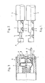
- Fig. 1 eine Seitenansicht einer ersten Ausführungsform einer Aderendhülse mit einer Sicke;
- Fig. 2 eine zur Fig. 1 entsprechende Seitenansicht einer zweiten Ausführungsform einer Aderendhülse mit einer umlaufenden Sicke;
- Fig. 3 eine geschnittene Seitenansicht einer Steckverbindung in Form einer Lampenfassung mit eingeschobener Aderendhülse der in Fig. 1 gezeigten Art.
- Figure 1 is a side view of a first embodiment of a ferrule with a bead.
- FIG. 2 shows a side view corresponding to FIG. 1 of a second embodiment of a wire end sleeve with a circumferential bead;
- Fig. 3 is a sectional side view of a connector in the form of a lamp holder with inserted wire end sleeve of the type shown in Fig. 1.
Die in Fig. 1 dargestellte erste Ausführungsform einer Aderendhülse 1 ist auf dem abisolierten Aderende 2 eines elektrischen Kabels 3 befestigt. Die Aderendhülse 1 wird dabei mittels eines entsprechenden Crimpwerkzeuges (Anschlagmaschine oder Handzange) auf dem Aderende 2 festgecrimpt. Zu diesem Zweck wird von einem V-förmigen Metallformteil ausgegangen, in das hinein das Aderende 2 des elektrischen Kabels 3 hineingelegt wird. Um die Tiefe dieses V-förmigen Formteils zu vergrößern, weisen dessen Schenkel sogenannte Haifischzähne auf, die beim Crimpen ineinandergreifen und eine Verzahnung 4 bilden, wie in Fig. 1 zu erkennen ist.The first embodiment of a wire end sleeve 1 shown in FIG. 1 is fastened on the stripped
Weiter ist in Fig. 1 zu erkennen, daß die Aderendhülse 1 auf der der Verzahnung 4 gegenüberliegenden Seite eine Sicke 5 aufweist. Diese kann während des Ancrimpvorganges mittels des entsprechenden Crimpwerkzeuges in die Aderendhülse 1 eingeprägt werden.It can also be seen in FIG. 1 that the wire end sleeve 1 has a
In Fig. 2 ist eine zweite Ausführungsform einer Aderendhülse 1 dargestellt. Der einzige Unterschied zu der in Fig. 1 darge stellten ersten Ausführungsform besteht lediglich darin, daß die Sicke 5 die Aderendhülse 1 vollständig umläuft, und zwar konzentrisch zu der Längsachse A.2 shows a second embodiment of a wire end sleeve 1. The only difference to that shown in Fig. 1 presented first embodiment consists only in that the
In Fig. 3 ist eine Steckverbindung als Steckfassung 6 in Form einer Lampenfassung dargestellt. Dabei sind in einem Gehäuse 7 zwei Kontaktfedern 8 angeordnet, deren Enden elastisch ausgebildet sind. An der Stirnseite ist das Gehäuse 7 mit zwei Öffnungen 9 versehen, durch die hindurch die mit Aderendhülsen 1 bestückten Aderenden 2 eines elektrischen Kabels 3 hineingesteckt und mit den Kontaktfedern 8 kontaktiert werden können. In Fig. 3 ist dabei lediglich dargestellt, wie durch die untere Öffnung 9 ein elektrisches Kabel 3 eingeschoben ist, das mit einer Aderendhülse 1 der in Fig. 1 dargestellten Ausführungsform versehen ist. In Fig. 3 ist dabei zu erkennen, daß das freie Ende der Kontaktfeder 8 nach dem Einschieben in der Sicke 5 der Aderendhülse 1 einrastet und somit diese und damit das Aderende 2 des elektrischen Kabels 3 in der Steckfassung 6 fixiert. In entsprechender Weise kann die in Fig. 2 dargestellte zweite Ausführungsform der Aderendhülse 1 innerhalb der Steckfassung 6 verrastet werden.In Fig. 3 a connector is shown as a
- 1 Aderendhülse1 ferrule
- 2 Aderende2 wire ends
- 3 elektrisches Kabel3 electrical cables
- 4 Verzahnung4 teeth
- 5 Sicke5 beads
- 6 Steckfassung6 jack
- 7 Gehäuse7 housing
- 8 Kontaktfeder8 contact spring
- 9 Öffnung9 opening
- A LängsachseA longitudinal axis
Claims (5)
dadurch gekennzeichnet,
daß die Aderendhülse (1) wenigstens eine Sicke (5) aufweist, in die die Kontaktfeder (8) nach Einstecken des Aderendes (2) in die elektrische Steckverbindung einrastet.1. wire end sleeve (1) for the stripped wire end (2) of an electrical cable (3) made of an electrically conductive material for electrically contacting the wire end (2) in an electrical contact spring (8) having an electrical plug connection,
characterized,
that the wire end sleeve (1) has at least one bead (5) into which the contact spring (8) snaps into the electrical plug connection after the wire end (2) has been inserted.
Applications Claiming Priority (2)
| Application Number | Priority Date | Filing Date | Title |
|---|---|---|---|
| DE3809322 | 1988-03-19 | ||
| DE3809322A DE3809322A1 (en) | 1988-03-19 | 1988-03-19 | ADERENDULE |
Publications (2)
| Publication Number | Publication Date |
|---|---|
| EP0334012A2 true EP0334012A2 (en) | 1989-09-27 |
| EP0334012A3 EP0334012A3 (en) | 1990-09-12 |
Family
ID=6350205
Family Applications (1)
| Application Number | Title | Priority Date | Filing Date |
|---|---|---|---|
| EP19890102465 Withdrawn EP0334012A3 (en) | 1988-03-19 | 1989-02-14 | Wire end sleeve |
Country Status (3)
| Country | Link |
|---|---|
| EP (1) | EP0334012A3 (en) |
| DE (1) | DE3809322A1 (en) |
| HU (1) | HUT49424A (en) |
Cited By (2)
| Publication number | Priority date | Publication date | Assignee | Title |
|---|---|---|---|---|
| GB2267606A (en) * | 1992-05-28 | 1993-12-08 | Electrolux Northern | Electrical contact. |
| DE102020110108A1 (en) | 2020-04-09 | 2021-10-14 | Tesona Gmbh & Co. Kg | Temperature sensor, especially for automotive applications |
Family Cites Families (9)
| Publication number | Priority date | Publication date | Assignee | Title |
|---|---|---|---|---|
| DE1065909B (en) * | 1959-09-24 | |||
| US2234820A (en) * | 1935-08-23 | 1941-03-11 | Kingston Products Corp | Electrical contact means |
| US3140142A (en) * | 1961-11-07 | 1964-07-07 | Ibm | Electrical connector |
| US3787800A (en) * | 1963-10-11 | 1974-01-22 | Eltra Corp | Resistor ignition lead |
| US3493917A (en) * | 1967-08-01 | 1970-02-03 | Viking Industries | Connector locking means |
| US3813643A (en) * | 1971-10-28 | 1974-05-28 | Essex International Inc | Terminating of electrical conductors |
| AT365003B (en) * | 1979-05-02 | 1981-12-10 | Neutrik Ag | CONTACT SOCKET TO RECEIVE A CONTACT PIN FOR ELECTRICAL CONTACTS |
| DE3105429A1 (en) * | 1981-02-14 | 1982-10-28 | Grote & Hartmann Gmbh & Co Kg, 5600 Wuppertal | Additional lock in a connector housing for an electrical connector |
| FR2579836B1 (en) * | 1985-03-27 | 1987-10-16 | Telemecanique Electrique | NOZZLE FOR ELECTRICAL CONDUCTOR AND MANUFACTURING METHOD THEREOF |
-
1988
- 1988-03-19 DE DE3809322A patent/DE3809322A1/en not_active Withdrawn
-
1989
- 1989-02-14 EP EP19890102465 patent/EP0334012A3/en not_active Withdrawn
- 1989-03-17 HU HU891270A patent/HUT49424A/en unknown
Cited By (3)
| Publication number | Priority date | Publication date | Assignee | Title |
|---|---|---|---|---|
| GB2267606A (en) * | 1992-05-28 | 1993-12-08 | Electrolux Northern | Electrical contact. |
| DE102020110108A1 (en) | 2020-04-09 | 2021-10-14 | Tesona Gmbh & Co. Kg | Temperature sensor, especially for automotive applications |
| DE102020110108B4 (en) | 2020-04-09 | 2024-07-25 | Tesona Gmbh & Co. Kg | Temperature sensor, especially for automotive applications |
Also Published As
| Publication number | Publication date |
|---|---|
| EP0334012A3 (en) | 1990-09-12 |
| DE3809322A1 (en) | 1989-09-28 |
| HUT49424A (en) | 1989-09-28 |
Similar Documents
| Publication | Publication Date | Title |
|---|---|---|
| DE2923399C2 (en) | Method for the electrical connection of a coaxial cable and connection fitting for coaxial cables | |
| DE19848344B4 (en) | Shielded socket | |
| DE3587104T2 (en) | ELECTRICAL PLUG DEVICE. | |
| DE181305T1 (en) | ELECTRICAL PLUG DEVICE. | |
| DE102013106117B4 (en) | Connector arrangement and connector system | |
| DE69116836T2 (en) | Strain relief for insulation displacement contact element | |
| DE2735838C2 (en) | Electrical terminal and electrical cable connector | |
| DE69221428T2 (en) | Electrical contact socket | |
| EP2345110B1 (en) | Plug connector for a star quad cable | |
| DE10143851B4 (en) | Plug with contact pin | |
| EP1467441A2 (en) | Connector for quick connection in collet attachment technologie | |
| EP0968548A1 (en) | Socket with contact regions disposed in the form of a hyperboloid | |
| EP0319633B1 (en) | Cinch connector | |
| EP0334012A2 (en) | Wire end sleeve | |
| DE2517465C3 (en) | Connectors | |
| DE2413445C2 (en) | Electrical hybrid connector | |
| DE2539675A1 (en) | BLIND-LIKE CONNECTORS AND CONTACT ELEMENTS FOR THESE | |
| DE4224155C2 (en) | Electrical connector assembly | |
| DE102014116482A1 (en) | contact element | |
| DE19506713C2 (en) | Multipole connector | |
| DE102005041922B4 (en) | Electrical connector with springy bridges | |
| EP4231463B1 (en) | Connector for mounting on a printed circuit board | |
| DE202005017981U1 (en) | Contact holder for electrical plug-in connections has insulating body to accommodate contact carrier, with apertures to accommodate contact pins | |
| DE2252145A1 (en) | LAMP HOLDER | |
| DE3314731C2 (en) | Plug contact socket |
Legal Events
| Date | Code | Title | Description |
|---|---|---|---|
| PUAI | Public reference made under article 153(3) epc to a published international application that has entered the european phase |
Free format text: ORIGINAL CODE: 0009012 |
|
| AK | Designated contracting states |
Kind code of ref document: A2 Designated state(s): DE ES FR GB IT |
|
| PUAL | Search report despatched |
Free format text: ORIGINAL CODE: 0009013 |
|
| AK | Designated contracting states |
Kind code of ref document: A3 Designated state(s): DE ES FR GB IT |
|
| STAA | Information on the status of an ep patent application or granted ep patent |
Free format text: STATUS: THE APPLICATION HAS BEEN WITHDRAWN |
|
| 18W | Application withdrawn |
Withdrawal date: 19900824 |
|
| R18W | Application withdrawn (corrected) |
Effective date: 19900824 |