EP0332200A2 - Positionierung-Servogerät - Google Patents
Positionierung-Servogerät Download PDFInfo
- Publication number
- EP0332200A2 EP0332200A2 EP89104221A EP89104221A EP0332200A2 EP 0332200 A2 EP0332200 A2 EP 0332200A2 EP 89104221 A EP89104221 A EP 89104221A EP 89104221 A EP89104221 A EP 89104221A EP 0332200 A2 EP0332200 A2 EP 0332200A2
- Authority
- EP
- European Patent Office
- Prior art keywords
- terminal
- resistor
- capacitors
- network
- filter
- Prior art date
- Legal status (The legal status is an assumption and is not a legal conclusion. Google has not performed a legal analysis and makes no representation as to the accuracy of the status listed.)
- Granted
Links
Images


Classifications
-
- G—PHYSICS
- G11—INFORMATION STORAGE
- G11B—INFORMATION STORAGE BASED ON RELATIVE MOVEMENT BETWEEN RECORD CARRIER AND TRANSDUCER
- G11B21/00—Head arrangements not specific to the method of recording or reproducing
- G11B21/02—Driving or moving of heads
- G11B21/08—Track changing or selecting during transducing operation
-
- G—PHYSICS
- G05—CONTROLLING; REGULATING
- G05D—SYSTEMS FOR CONTROLLING OR REGULATING NON-ELECTRIC VARIABLES
- G05D3/00—Control of position or direction
- G05D3/12—Control of position or direction using feedback
- G05D3/14—Control of position or direction using feedback using an analogue comparing device
- G05D3/1445—Control of position or direction using feedback using an analogue comparing device with a plurality of loops
-
- G—PHYSICS
- G11—INFORMATION STORAGE
- G11B—INFORMATION STORAGE BASED ON RELATIVE MOVEMENT BETWEEN RECORD CARRIER AND TRANSDUCER
- G11B21/00—Head arrangements not specific to the method of recording or reproducing
- G11B21/02—Driving or moving of heads
- G11B21/08—Track changing or selecting during transducing operation
- G11B21/081—Access to indexed tracks or parts of continuous track
- G11B21/083—Access to indexed tracks or parts of continuous track on discs
-
- G—PHYSICS
- G11—INFORMATION STORAGE
- G11B—INFORMATION STORAGE BASED ON RELATIVE MOVEMENT BETWEEN RECORD CARRIER AND TRANSDUCER
- G11B21/00—Head arrangements not specific to the method of recording or reproducing
- G11B21/02—Driving or moving of heads
- G11B21/10—Track finding or aligning by moving the head ; Provisions for maintaining alignment of the head relative to the track during transducing operation, i.e. track following
- G11B21/106—Track finding or aligning by moving the head ; Provisions for maintaining alignment of the head relative to the track during transducing operation, i.e. track following on disks
-
- G—PHYSICS
- G11—INFORMATION STORAGE
- G11B—INFORMATION STORAGE BASED ON RELATIVE MOVEMENT BETWEEN RECORD CARRIER AND TRANSDUCER
- G11B5/00—Recording by magnetisation or demagnetisation of a record carrier; Reproducing by magnetic means; Record carriers therefor
- G11B5/48—Disposition or mounting of heads or head supports relative to record carriers ; arrangements of heads, e.g. for scanning the record carrier to increase the relative speed
- G11B5/54—Disposition or mounting of heads or head supports relative to record carriers ; arrangements of heads, e.g. for scanning the record carrier to increase the relative speed with provision for moving the head into or out of its operative position or across tracks
- G11B5/55—Track change, selection or acquisition by displacement of the head
- G11B5/5521—Track change, selection or acquisition by displacement of the head across disk tracks
- G11B5/5526—Control therefor; circuits, track configurations or relative disposition of servo-information transducers and servo-information tracks for control thereof
- G11B5/553—Details
- G11B5/5547—"Seek" control and circuits therefor
-
- G—PHYSICS
- G11—INFORMATION STORAGE
- G11B—INFORMATION STORAGE BASED ON RELATIVE MOVEMENT BETWEEN RECORD CARRIER AND TRANSDUCER
- G11B5/00—Recording by magnetisation or demagnetisation of a record carrier; Reproducing by magnetic means; Record carriers therefor
- G11B5/48—Disposition or mounting of heads or head supports relative to record carriers ; arrangements of heads, e.g. for scanning the record carrier to increase the relative speed
- G11B5/58—Disposition or mounting of heads or head supports relative to record carriers ; arrangements of heads, e.g. for scanning the record carrier to increase the relative speed with provision for moving the head for the purpose of maintaining alignment of the head relative to the record carrier during transducing operation, e.g. to compensate for surface irregularities of the latter or for track following
- G11B5/596—Disposition or mounting of heads or head supports relative to record carriers ; arrangements of heads, e.g. for scanning the record carrier to increase the relative speed with provision for moving the head for the purpose of maintaining alignment of the head relative to the record carrier during transducing operation, e.g. to compensate for surface irregularities of the latter or for track following for track following on disks
- G11B5/59605—Circuits
- G11B5/59622—Gain control; Filters
Definitions
- This invention relates to a servo positioning apparatus, for example for use in positioning a read/write head of a magnetic recording disk, and more particularly concerns a filter used in a feedback loop of servo control circuitry of the apparatus.
- Servo positioning apparatuses have been widely employed for quickly and accurately positioning mechanical elements, such as a magnetic head in a magnetic recording disk apparatus.
- a typical servo control system of such disk apparatus is illustrated in Fig. 1.
- Magnetic recording disks 10 are mounted on an axle 11, driven to spin by a spindle motor 12.
- Magnetic heads 13 are mounted on accessors 140 which are connected to a movable part of a voice coil motor 14.
- the accessors 140 are moved in an essentially radial direction of the disks 10 by a coil 141 and a magnet 142 of the voice coil motor.
- Positions or speeds hereinafter referred to relate to positions or speeds in radial directions of the disks 10, i.e. in a seek direction.
- the above-mentioned parts are installed in a magnetic disk unit 1 enclosed in a disk enclosure 16.
- the disk unit 1 is mounted in a main chassis of a magnetic disk apparatus but is detachable therefrom, for servicing, etc.
- a coarse controller i.e. a velocity control circuit 2 generates a velocity error signal ⁇ V depending on a position signal PS obtained from a servo signal generated from a magnetic head 13. Details of the controller 2 are described below.
- the position signal PS indicates radial position (of the magnetic head) relative to an adjacent track (on a disk 10), and is generally designed to be zero when the head is positioned on a centre line of a track to be traced.
- a fine controller (i.e. a position controller) 3 generates a position error signal ⁇ P from the phase-compensated position signal PS processed using proportional control (P), derivative control (D) and integral control (I).
- a controller 4 composed of a microprocessor calculates a number of tracks to be jumped, according to an instruction from an upper processor unit, then switches coarse/fine modes by outputting a mode switching signal MS to a switch 5, and outputs instructions to the coarse controller 2 and fine controller 3, each to drive the voice coil motor 14.
- the coarse controller 2, the fine controller 3, the controller 4 and the switch 5 constitute a servo controller CT.
- the switch 5 connects one terminal "a" to the output of the servo controller CT and accordingly a driving current proportional to the velocity error signal ⁇ V is supplied from a power amplifier 6 to the voice coil motor 14.
- the magnetic head 13 is moved to a destination track in accordance with a predetermined velocity schedule depending on a difference between a target velocity V c and an actual velocity V r of the head 13 obtained from the position signal PS.
- the controller 4 switches the switch 5 to connect a terminal "b" to the output of the servo controller CT.
- ⁇ indicates the width of a track to be traced
- MS indicates a signal for switching switch 5.
- the fine controller 3 delivers the position error signal ⁇ P to the amplifier 6. Accordingly, a driving current I m proportional to the position error signal ⁇ P (when terminal "a" was connected I m was proportional the velocity error signal ⁇ V) is supplied from the power amplifier 6 to the voice coil motor 14. Thus, the head is controlled to trace or move to a destination track.
- a notch filter 32 has been widely employed in the servo loop (i.e. feedback loop) of the servo positioning apparatus, in order to damp undesirable oscillation of the heads 13 caused by the mechanical resonance.
- a fine position amplifier 30 generates from the position signal PS a signal which becomes zero volts when the head is located at the centre of a track, and takes positive or negative values proportional to deviations of the head from the centre of the track to one side or the other.
- a clamp circuit 31 generates a clamped position signal, which is a modification of the signal output from the fine position amplifier 30 which saturates at predetermined positive and negative levels.
- a notch filter 32 has an attenuation characteristic as shown in Fig. 5(B), such that attenuation is maximum at the frequency f0 of a mechanical resonance.
- a second filter 33 attenuates high-frequency gain of the servo loop in order to attain a stable servo operation.
- a phase compensation circuit 34 is also provided for attaining a stable servo operation.
- An integrator circuit 34a integrates an output from the second filter 33 for integral control, an amplifier 34b amplifies the output from the second filter 33 for proportional control, and a differentiator circuit 34c differentiates the output from the second filter 33 for derivative control.
- An adder circuit 34d adds the outputs from the integrator circuit 34a, the amplifier 34b and the differentiator circuit 34c, then outputs the position error signal ⁇ P to the switch 5.
- the notch filter 32 is typically composed of a twin T-type filter as shown in Fig. 5(a).
- a parallel connection of capacitors C1 and C2 connected to a connecting point of resistors r1 and r2 forms a first T-type network.
- a series connection of resistors r3 and r4 connected to a connecting point of capacitors C3 and C4 forms a second T-type network.
- These two T-type networks are connected in parallel to form a twin T-type filter.
- An output from resistor r2 and capacitor C4 is input to an amplifier AMP1 having a unity gain.
- An output of amplifier AMP1 is divided by resistors r5 and r6, and the divided output level is input to another amplifier AMP2 having a unity gain.
- Output of the second amplifier AMP2 is fed to a return terminal t3, which is the connecting point of capacitors C1, C2 and resistor r4.
- a problem with the twin T-type filter is in that all of the four resistors r1 to r4 or all of the four capacitors C1 to C4 must be replaced according to the formula (1) for adjusting the resonant frequency while keeping the attenuation unchanged, when the disk unit 1 is replaced for servicing, etc.
- notch filter which may be employed in the servo control circuit is a bridged T-type filter as shown in Fig. 6. Problems with this type of filter are that the available attenuation is not adequate, for example -12 dB, and three or four capacitors or resistors must be replaced for adjusting the resonant frequency while keeping the attenuation unchanged.
- Disk units do not always have the same resonant frequency even if they are of the same design, and furthermore if the design is changed, for reasons of improvement, etc., the resonant frequency consequently changes.
- the notch filter is generally mounted on a printed circuit board, which is installed in a main chassis on which the disk apparatus is installed. The exchange of the three or four circuit elements is a time-consuming job requiring a precise instrument. Exchange of the printed circuit board is of course expensive. In any event, costs of production and servicing are considerable.
- the notch filter may be mounted on the replaceable (detachable) disk unit 1, in which the notch frequency is tuned at the factory, as disclosed in Japanese Unexamined Patent Publication Tokukai Sho 58-188374.
- a problem still remains in that frequency adjustment is a troublesome job even in a factory production line.
- An embodiment of the present invention can provide an efficiently adjustable filter used in a servo positioning apparatus, applicable for example to positioning of a read/write head of a magnetic recording disk.
- An embodiment of the present invention can provide for an exchangeable disk unit structure which is economical in terms of its servicing characteristics.
- servo positioning apparatus comprising:- a mechanism for positioning an object, the mechanism having a resonant frequency; and a controller for providing a servo signal derived from a position signal representing position of the object, for example relative to a track to be traced by the object, said controller including:- a bridged serial T-type notch filter having a notch frequency substantially equal to said resonant frequency.
- servo positioning apparatus comprising:- a mechanism for positioning an object, the mechanism being installed in a unit detachable from other portions of the apparatus, the mechanism having a resonant frequency; and a controller for providing a servo signal derived from a position signal representing position of the object, for example relative to a track to be traced by the object, said controller including:- a notch filter having a notch frequency substantially equal to said resonant frequency, an element for tuning said notch frequency being separately installed in said unit.
- servo positioning apparatus comprising:- a mechanism for positioning an object, said mechanism being installed in a disk unit, said mechanism having a resonant frequency; and a controller for providing a servo signal derived from a position signal representing position of the object relative to a track to be traced by the object, said controller including:- a bridged serial T-type notch filter having a notch frequency substantially equal to said resonant frequency, said filter comprising a network composed of:- a serial circuit of first to third capacitors connecting an input terminal of said network and an output terminal of said network; a first resistor connected in parallel to said serial circuit of said first to third capacitors; and second and third resistors serially connected between a third terminal of said network and an interconnection point of said first and second capacitors, an end of said third resistor being connected to said third terminal; and fourth and fifth resistors serially connected between said third terminal and an interconnection point of said second and third capacitors, an end of said fifth resistor being connected to
- a notch filter used in a servo loop for dampening a mechanical resonance of moving parts of the mechanism to be servo controlled has a CR (capacitor resistor) network including a serial connection of first to third capacitors having approximately equal capacitance values connected between an input terminal of the filter and an output terminal of the CR network; a first resistor connected between a return terminal of the CR network and an interconnection of the first and second capacitors; a second resistor connected between the return terminal and an interconnection of the second and third capacitors; and a third resistor connected in parallel to the three serial capacitors.
- CR capacitor resistor
- the notch frequency of the filter is adjusted by varying the resistance values of only the first and second resistors.
- the first and second resistors may be composed of fixed and/or potentiometer-type variable resistor(s) whose variable terminal then becomes the return terminal.
- An output from the CR network may be divided to be fed back to the return terminal.
- the resistor(s) for adjusting the notch frequency may be separately installed in a detachable disk unit including the mechanism to be servo controlled.
- the detachable disk unit is less expensive and, furthermore, the detachable disk unit may be prepared to have an individual notch frequency tuned to the resonant frequency of the individual mechanism beforehand in the factory.
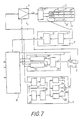
- FIG. 7 an apparatus for servo positioning read/write heads of a recording disk system, in which an embodiment of the present invention can be applied, is representatively described hereinafter.
- Magnetic recording disks 10 are mounted on an axle 11 driven to spin by a spindle motor 12.
- Magnetic heads 13 are connected to a coil of a voice coil motor 14. The heads 13 are moved in an essentially radial direction of the disks 10 by the voice coil motor 14.
- a position signal generator 7 generates a position signal PS depending on a servo signal SVS produced by one of the heads 13 which reads servo signals of the track the head is currently on and its adjacent track both recorded on a servo surface (typically the lower surface of the second disk).
- the position signal generator 7 includes an AGC (automatic gain control) amplifier 70, which keeps the servo signal SVS at an essentially constant amplitude; and a position signal detector 71, which decodes the AGC-controlled servo signal SVS to provide a position signal PS (as shown in Fig. 2).
- a target velocity generator 20 in the velocity controller 2 generates a target velocity V c , according to a predetermined schedule that typically consists of a constant acceleration section, a constant velocity section and a constant deceleration section, depending on the number of tracks to be jumped, the number being instructed from a controller 4.
- a velocity signal generator 21 generates a velocity signal V r , which indicates proportionally the actual velocity of the head depending on the position signal PS and an indication current i i , which indicates proportionally the amplitude of a driving current I m of voice coil motor 14 supplied from the power amplifier 6.
- An error signal generator 22 generates and supplies a velocity error ⁇ V depending on the difference between the target velocity V c and the velocity signal V r to switch 5. Accordingly, the head 13 driven by the voice coil motor 14 moves with thus given velocity to the destination track.
- the controller 4 is composed of a microprocessor to receive a seek instruction and a destination track number given from an upper (higher level) processing device and outputs instructions for the seek control.
- the controller 4 calculates a number of tracks to be jumped, for output to the target velocity generator 20.
- the controller 4 On arrival of the head 13 at the destination track as shown in Fig. 2, the controller 4 detects this fact from the position signal PS and outputs a coarse/fine switching signal MS to the switch 5, to change the switch from its "a" position to its "b” position, i.e.
- the controller 4 has also a function of outputting a seek end signal to the upper (higher level) processing device when a seek operation is finished.
- a fine controller 3 is composed of: a fine position amplifier 30 which generates, in dependence upon the position signal PS, a signal which has a neutral voltage (e.g. zero volts) when the head is located at the centre of a track, and becomes more positive or more negative in proportion to deviation from the centre of the track to one side or the other; a clamp circuit 31, which generates a clamped position signal, this being a modification of the signal output from the fine position amplifier 30 such that it saturates at predetermined positive and negative levels; a notch filter 32, which has a notch frequency equal to a mechanical resonant frequency f0 of moving parts of the mechanism to be servo controlled, i.e.
- a second filter 33 composed of a low pass filter, is connected to the output of the notch filter 32 in order to attenuate high-frequency gain of the servo loop so as to remove noise and to achieve a stable servo operation.
- a phase compensation circuit 34 is connected to the output of the second filter 33 so as to attain a stable quality servo operation.
- the phase compensation circuit 34 includes: an integrator circuit 34a for integrating an output from the second filter 33 for integral control; an amplifier 34b for amplifying the output from the second filter 33 for proportional control; and a differentiator circuit 34c for differentiating the output from the second filter 33 for derivative control.
- An adder circuit 34d adds outputs from the integrator circuit 34a, the amplifier 34b and the differentiator circuit 34c, then outputs the thus derived position error signal ⁇ P to the switch 5.
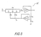
- FIG. 8 there is shown a practical schematic circuit diagram of a bridged serial T-type filter of an embodiment of the present invention, to be used as the notch filter 32′ in Fig. 7.
- a serial connection of capacitors C1, C2 and C3 is connected between an input terminal t1 and an output terminal t2 of a CR (capacitor, resistor) network.
- a first resistor R1 connects a return terminal t3 and a connection point of the capacitors C1 and C2.
- a second resistor R2 connects the return terminal t3 and a connection point of the capacitors C2 and C3.
- a third resistor R3 connects, i.e. bridges, the ends of the serial connection of the capacitors C1 to C3.
- An output from the output terminal t2 of the CR network is input to an amplifier AMP1 having generally a unity gain.
- An output of amplifier AMP1 having generally a unity gain.
- An output of amplifier AMP1 is divided by resistors R4 and R5, and the divided output level is input to a second amplifier AMP2 having generally a unity gain.
- the first amplifier AMP1 isolates the CR network from effects of input impedance of the next stage, i.e. the second filter 33, and the divider resistors R4 and R5.
- the output of the second amplifier AMP2 is connected to the return terminal t3.
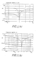
- the notch frequency can be shifted as shown in Fig. 9(a) from f0 to f0′ by changing the resistance values of R1 and R2.
- resistance value R3 287 k ohm
- the effect of the varied resistance on the notch frequency is shown in Fig. 9(b).
- a notch frequency variation of more than 1 kHz is achieved, which is adequate to cover variation of the resonant frequencies (in the servo system).
- the division ratio of the output of the amplifier AMP1 by the resistors R4 and R5 determines the feedback ration (R4/R4+R5) to the network.
- the effects of the feedback ratio on band width of the notch frequency f0 are shown in Fig. 10, where the values of the elements in the CR network are the same as those mentioned above.
- Attenuation at the notch frequency can also be kept essentially unvaried when notch frequency is varied corresponding to the case of Fig. 9(b). Then, attenuation at the notch frequency can be as much as or more than 40 dB, which is adequate for dampening mechanical resonance in the feedback system, even if some drift of frequency takes place.
- the bridged T-type filter shown in Fig. 6 achieves only -12 dB at most.
- Phase rotation by the notch filter is a factor to be controlled in the servo control system, particularly at a lower frequency band, typically from 300 to 800 Hz, at which the servo mechanism is driven most often. If phase rotation is excessive in this band the stability of the servo system is deteriorated.
- Phase characteristics of the notch filter having the above-mentioned element values and a feedback ratio of 0.95 are shown in Fig. 11(a). As seen in these characteristics, the amount of phase rotation at 800 Hz is 10° which is fully satisfactory.
- a similar filter having feedback ratio of zero, i.e. the return terminal t3 is grounded, is shown in Fig. 11(b).
- the bridged T-type filter of Fig. 6 can have a problem with phase rotation, as can the filter of Fig. 5(a).
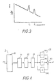
- x/i is then calculated.
- the gain versus frequency curve is plotted as shown in Fig. 3. Location of the peak of the gain curve represents the mechanical resonant frequency f0.
- the thus obtained resonant frequency f0 is input into equation (3) to obtain resistance values for R1 and R2.
- the resistors R1 and R2 are adjusted to have thus calculated resistance values.
- the first and second resistors R1 and R2 consist of a resistor R1′ plus an additional resistor R1 ⁇ (Fig. 12(a)) or an additional resistor R6′ (Fig. 12(b)); and a resistor R2′ plus an additional resistor R2 ⁇ (Fig. 12(a)) or R7′ (Fig. 12(b)), respectively.
- the sum of the resistance values of the resistors R1′, R2′, R1 ⁇ (or R6′) and R2 ⁇ (or R7′) are kept essentially to one-sixth of the resistance value R3 to satisfy equation (2).
- Adjustment of the notch frequency f0 is carried out by changing the resistance values of R1 ⁇ and/or R2 ⁇ for the configuration of Fig. 12(a), or simply selecting (by means of a switch SW) one of connection points A, B or C (each at an interconnecting point of resistors R1′, R6′, R7′ and R2′) as the return terminal t3 to which the feedback from amplifier AMP2 is connected for the configuration of Fig. 12(b).
- the resistance values of the first and second resistor R1 and R2 of equation (3) are varied.
- notch frequency can be selected to tune to three different frequencies to meet the resonant frequency f0 of the mechanism of the magnetic disk unit 1.
- the number of taps or connection point for additional resistors can be arbitrarily chosen depending on design requirements; that is, two taps between resistors R1 and R2′ allow selection of two frequencies, whilst four taps allow selection of four frequencies as well.
- the two resistors R ⁇ and R2 ⁇ used in Fig. 12(a) may be replaced with a potentiometer-type variable resistor R8 as shown in Fig. 13.
- Two fixed ends, denoted by “m” and “n”, of the variable resistor R8 are connected to resistors R1 ⁇ and R2′, respectively.
- the sum of resistance values of resistors R1′, R2′ and fixed part of R8 is essentially one-sixth of that of resistor R3.
- a variable terminal "l" of the variable resistor R8 corresponds to the return terminal t3 to which the output of the second amplifier AMP2 is connected. Accordingly, frequency adjustment can be effected precisely and efficiently by observing frequency characteristics of the filter on a spectrum analyser display whilst the input frequency to the filter is swept, or by calculation from equation (3).
- frequency adjusting elements such as two resistors R6′ and R7′ used in Fig. 12(a), the resistors R6′, R7 and their switch SW used in Fig. 12(B), or the potentiometer-type variable resistor R8 may be installed in a circuit board 17 mounted on a disk unit 1, separately from the below-described main portion of the filter, as illustrated in Fig. 13.
- Fig. 13 illustrates representatively the case where the variable resistor R8 is employed.
- the magnetic recording disks 10 the spindle motor 12, the read/write head 13 and the voice coil motor to drive the heads 13 are also installed.
- the disk unit 1 is detachable from the main chassis of the magnetic disk drive apparatus, for facilitating replacement of recorded disks or servicing of a defective unit.
- the main portion of the notch filter 32 including the elements which require no adjustment, such as capacitors C1 to C3, resistors R1′, R2′ and R3, the amplifiers AMP1 and 2, are installed on a printed circuit board (which is given reference numeral 32 ⁇ in Fig. 13) in a main chassis of the magnetic disk drive apparatus.
- the resistance values and the capacitance values of the filter can be kept essentially same and constant for each product.
- each one of the completed units 1 is first mounted in the main chassis of the magnetic recording apparatus, as an adjusting jig.
- the mechanical resonance characteristics of the unit is measured according, for example, to the method described above.
- the resistors R1 ⁇ and R2′ or the variable resistor R8 installed in the unit 1 is adjusted so that the notch frequency is tuned to the mechanical resonant frequency of this mounted unit according to the above-described method.
- the disk unit 1 is removed from the main chassis, so as to be a stock for shipment.
- the new unit needs no more frequency adjustment, resulting in efficient servicing.
- the electronic circuit installed in the disk unit 1, which must be replaced upon servicing, can be made less expensive, because the main portion of the filter does not have to be exchanged. Therefore, servicing costs can be reduced both in terms of time required and hardware cost.
- a mechanism generally has two or more resonances.
- the notch filter is typically tuned to the major one of the resonances.
- a first amplifier AMP1 is provided to isolate the CR network from the effects of the dividing resistors and the input impedance of the second filter 33, the first amplifier AMP1 may be omitted, as long as the effects of the dividing resistors and the input impedance of the second filter 33 are negligible or within a degree adjustable by the CR network.
- a second amplifier AMP2 is provided to isolate the network from the effects of the dividing resistors, the second amplifier AMP2 may be omitted, as long as the effects of the dividing resistors is negligible or within a degree adjustable by the CR network.
- the capacitance values of the capacitors C1 to C3 are chosen essentially equal, the capacitance values may be different from each other as long as the effects of the different capacitances is negligible or within a degree adjustable by the CR network.
- the sum of the resistance values of the capacitors R1 and R2 is chosen essentially one-sixth of the resistance values of the resistor R3, the resistance values may be deviated from this condition as long as the effect is negligible or within a degree adjustable by the network.
- Embodiments of the invention are applicable to servo positioning apparatus in any other kind of system, such as an optically recording disk apparatus, etc.
- a notch filter used in a servo loop, for dampening a mechanical resonance of moving parts of the mechanism to be servo controlled, is composed of a serial T-type filter, that is a CR network including a serial connection of first to third capacitors connected between an input terminal of the filter and an output terminal of the CR network; a first resistor connected between a return terminal of the CR network and an interconnection of the first and second capacitors; a second resistor connected between the return terminal and an interconnection of the second and third capacitors; and a third resistor connected in parallel to the three serial capacitors.
- the notch frequency is adjusted by varying the resistance values of the first and second resistors.
- the first and second resistors may be composed of fixed resistors and/or potentiometer-type variable resistors.
- An output from the CR network may be divided to be fed back to the return terminal.
- Isolation amplifiers may be added to the output circuit and the feedback circuit to the return terminal.
- Only the resistor(s) for adjusting the notch frequency may be separately installed in a detachable disk unit including the mechanism to be servo controlled. The notch frequency can be efficiently adjusted by replacing only two fixed resistors or adjusting a variable resistor, and the cost of the disk unit can be reduced.
- the present invention provides servo positioning apparatus having a mechanism for positioning an object, for example a magnetic head in a magnetic disk recording system, and a controller for providing a servo signal derived from a position signal representing position of the object, for example relative to a track to be traced on a disk.
- the controller has a notch filter, the notch frequency of which corresponds to a resonance of the mechanism.
- Components of the notch filter network for example resistors, which can be exchanged or varied, to alter the notch frequency, are separately installed from other components, so that they may be more easily accessed or exchanged, without need to access or exchange the other components.
- the notch filter has a bridged serial T configuration with a series connection of capacitors, for example three capacitors, with a parallel-connected resistor, and with further resistors connected respectively to interconnection points between successive capacitors of the series.
- Notch frequency can be altered by exchanging or varying these further resistors, which are thus the components to be separately mounted.
Landscapes
- Physics & Mathematics (AREA)
- General Physics & Mathematics (AREA)
- Engineering & Computer Science (AREA)
- Automation & Control Theory (AREA)
- Control Of Position Or Direction (AREA)
- Moving Of The Head To Find And Align With The Track (AREA)
- Control Of Electric Motors In General (AREA)
- Control Of Linear Motors (AREA)
Applications Claiming Priority (2)
| Application Number | Priority Date | Filing Date | Title |
|---|---|---|---|
| JP63056979A JPH0820905B2 (ja) | 1988-03-10 | 1988-03-10 | サーボ位置決め装置 |
| JP56979/88 | 1988-03-10 |
Publications (3)
| Publication Number | Publication Date |
|---|---|
| EP0332200A2 true EP0332200A2 (de) | 1989-09-13 |
| EP0332200A3 EP0332200A3 (en) | 1989-11-29 |
| EP0332200B1 EP0332200B1 (de) | 1995-05-03 |
Family
ID=13042626
Family Applications (1)
| Application Number | Title | Priority Date | Filing Date |
|---|---|---|---|
| EP89104221A Expired - Lifetime EP0332200B1 (de) | 1988-03-10 | 1989-03-09 | Positionierung-Servogerät |
Country Status (5)
| Country | Link |
|---|---|
| US (1) | US4963806A (de) |
| EP (1) | EP0332200B1 (de) |
| JP (1) | JPH0820905B2 (de) |
| KR (1) | KR920003996B1 (de) |
| DE (1) | DE68922425T2 (de) |
Cited By (3)
| Publication number | Priority date | Publication date | Assignee | Title |
|---|---|---|---|---|
| EP0577839A4 (de) * | 1992-01-23 | 1994-03-23 | Fanuc Ltd. | |
| FR2810419A1 (fr) * | 2000-06-19 | 2001-12-21 | Lucas Aerospace Fcs | Dispositif de cervo-commande de position, notamment pour actionneur de commande de vol d'aeronef |
| GB2357893B (en) * | 1998-06-26 | 2002-12-11 | Seagate Technology Llc | Improved notch filtering as used in a disc drive servo |
Families Citing this family (33)
| Publication number | Priority date | Publication date | Assignee | Title |
|---|---|---|---|---|
| JPH02278582A (ja) * | 1989-04-20 | 1990-11-14 | Fujitsu Ltd | 位置制御回路 |
| JP3064336B2 (ja) * | 1989-06-28 | 2000-07-12 | 株式会社日立製作所 | 情報取扱い装置およびデイスク装置 |
| JP2774327B2 (ja) * | 1989-10-06 | 1998-07-09 | 日本電信電話株式会社 | 位置決め装置 |
| US5231550A (en) * | 1990-03-12 | 1993-07-27 | Fujitsu Limited | Track access control system preventing unintentional delay in movement of head in non-adjusted disc device |
| JP2504307B2 (ja) * | 1990-08-01 | 1996-06-05 | 三菱電機株式会社 | 電動機の速度制御装置 |
| JPH04178185A (ja) * | 1990-11-07 | 1992-06-25 | Matsushita Electric Ind Co Ltd | 電気機械変換素子の駆動装置 |
| US5459383A (en) * | 1991-02-07 | 1995-10-17 | Quantum Corporation | Robust active damping control system |
| US5206570A (en) * | 1991-03-19 | 1993-04-27 | Maxtor Corporation | Actuator servo compensation method |
| US5220262A (en) * | 1992-02-25 | 1993-06-15 | Cincinnati Milacron, Inc. | Method and apparatus for reducing cross-coupled movement through the structural dynamics of a computer numerically controlled machine |
| WO1994001861A1 (en) * | 1992-07-10 | 1994-01-20 | Wangtek, Inc. | Servo controlled magnetic head positioner |
| US5325247A (en) * | 1992-11-12 | 1994-06-28 | Quantum Corporation | Digital multi-rate notch filter for sampled servo digital control system |
| EP1674974A3 (de) * | 1994-06-07 | 2007-03-21 | Hitachi, Global Storage Technologies Japan, Ltd. | Gerät zum Speichern von Information |
| US5671098A (en) * | 1995-06-01 | 1997-09-23 | Maxtor Corporation | Adaptive preamplifier for resonance tuning useful in a disk drive |
| US6122125A (en) * | 1997-08-28 | 2000-09-19 | International Business Machines Corporation | Head selectable servo notch filter and method for improving servo system performance |
| US6107767A (en) * | 1998-03-20 | 2000-08-22 | Trw Inc. | Electric assist steering system having an improved motor current controller with notch filter |
| US7483232B2 (en) * | 1999-03-04 | 2009-01-27 | Convolve, Inc. | Dynamic system control method |
| JP2000322105A (ja) * | 1999-05-07 | 2000-11-24 | Toshiba Mach Co Ltd | サーボ制御装置およびサーボ制御装置の安定化調整方法 |
| US6643080B1 (en) | 1999-08-25 | 2003-11-04 | Seagate Technology Llc | Resonance identification by commanding a spindle speed change |
| EP1226476B1 (de) * | 1999-09-08 | 2004-04-07 | Dr. Johannes Heidenhain GmbH | Verfahren und schaltungsanordnung zur erzeugung von lagesollwerten für einen lageregelkreis einer numerisch bahngesteuerten maschine |
| US6624607B1 (en) * | 1999-11-18 | 2003-09-23 | Parker-Hannifin Corporation | Energy-absorbing filter for a motor |
| JP4691753B2 (ja) * | 2000-03-31 | 2011-06-01 | ソニー株式会社 | 音質調整回路 |
| WO2001097215A1 (en) * | 2000-06-09 | 2001-12-20 | Seagate Technology Llc | Reducing actuator arm oscillation during settle mode in a disc drive servo system |
| JP3699882B2 (ja) * | 2000-06-26 | 2005-09-28 | 株式会社日立グローバルストレージテクノロジーズ | ヘッド位置決め装置 |
| JP3975812B2 (ja) * | 2001-08-17 | 2007-09-12 | 株式会社安川電機 | 電動機制御装置の共振周波数検出装置 |
| JP4110358B2 (ja) * | 2001-09-04 | 2008-07-02 | 株式会社安川電機 | 電動機制御装置の機械モデル推定装置 |
| US6710965B2 (en) | 2001-10-02 | 2004-03-23 | Seagate Technology Llc | Phase-advanced filter for robust resonance cancellation |
| JP3956120B2 (ja) | 2002-08-23 | 2007-08-08 | インターナショナル・ビジネス・マシーンズ・コーポレーション | データ記憶装置、サーボ制御方法およびプログラム |
| US6836032B2 (en) * | 2002-11-14 | 2004-12-28 | Levram Medical Systems, Ltd. | Electromagnetic moving-coil device |
| US7136260B2 (en) * | 2003-07-10 | 2006-11-14 | Samsung Electronics Co., Ltd. | Method and apparatus reducing off track head motion due to disk vibration in a hard disk drive through the head gimbal assembly |
| US6958879B2 (en) * | 2003-07-10 | 2005-10-25 | Samsung Electronics Co., Ltd. | Method and apparatus reducing off track head motion due to disk vibration in a hard disk drive using configuration of the disk drive servo controller |
| JPWO2008146365A1 (ja) * | 2007-05-29 | 2010-08-12 | 東芝ストレージデバイス株式会社 | コントローラ及び記憶装置 |
| JP5778925B2 (ja) | 2010-12-24 | 2015-09-16 | セミコンダクター・コンポーネンツ・インダストリーズ・リミテッド・ライアビリティ・カンパニー | モータ駆動回路 |
| EP3800788A1 (de) * | 2014-06-11 | 2021-04-07 | Catena Holding bv | Verfahren zur verwendung eines präzise einstellbaren hochfrequenz-phasendetektors zur phaseneinstellung zwischen zwei differentiellen eingangsspannungssignalen |
Family Cites Families (10)
| Publication number | Priority date | Publication date | Assignee | Title |
|---|---|---|---|---|
| US2996689A (en) * | 1960-05-24 | 1961-08-15 | Donald W F Janz | Constant d.-c. resistance frequency variable t-t notch network |
| GB1577132A (en) * | 1976-03-19 | 1980-10-22 | Rca Corp | Compensation apparatus for a servo system with periodic command signals |
| US4268785A (en) * | 1979-09-13 | 1981-05-19 | Ampex Corporation | Transient overshoot, undershoot and delay compensation circuit in systems comprising reactive filter networks |
| US4540946A (en) * | 1980-06-06 | 1985-09-10 | National Research Development Corp. | Variable characteristic filters |
| JPS5868316A (ja) * | 1981-10-19 | 1983-04-23 | Nippon Koden Corp | ノツチフイルタ |
| JPS6014525U (ja) * | 1983-07-07 | 1985-01-31 | 日本光電工業株式会社 | ノツチフイルタ |
| JPH0626039B2 (ja) * | 1983-10-31 | 1994-04-06 | ソニー株式会社 | 磁気ヘツドの変位駆動装置 |
| US4638384A (en) * | 1985-11-19 | 1987-01-20 | Rodime, Plc | Head positioning mechanism for rotating disk data storage system |
| JPH0664481B2 (ja) * | 1985-11-27 | 1994-08-22 | オムロン株式会社 | Xyステ−ジ制御装置 |
| JPS62269203A (ja) * | 1986-05-16 | 1987-11-21 | Fujitsu Ltd | 位置決め制御系のノツチフイルタ調整方法 |
-
1988
- 1988-03-10 JP JP63056979A patent/JPH0820905B2/ja not_active Expired - Fee Related
-
1989
- 1989-02-24 KR KR1019890002216A patent/KR920003996B1/ko not_active Expired
- 1989-03-09 DE DE68922425T patent/DE68922425T2/de not_active Expired - Fee Related
- 1989-03-09 EP EP89104221A patent/EP0332200B1/de not_active Expired - Lifetime
- 1989-03-09 US US07/321,108 patent/US4963806A/en not_active Expired - Lifetime
Cited By (4)
| Publication number | Priority date | Publication date | Assignee | Title |
|---|---|---|---|---|
| EP0577839A4 (de) * | 1992-01-23 | 1994-03-23 | Fanuc Ltd. | |
| GB2357893B (en) * | 1998-06-26 | 2002-12-11 | Seagate Technology Llc | Improved notch filtering as used in a disc drive servo |
| FR2810419A1 (fr) * | 2000-06-19 | 2001-12-21 | Lucas Aerospace Fcs | Dispositif de cervo-commande de position, notamment pour actionneur de commande de vol d'aeronef |
| EP1168132A1 (de) * | 2000-06-19 | 2002-01-02 | TRW Systemes Aeronautiques Civils | Positionsservosteuerungsvorrichtung, insbesondere für den Flugsteuerstellantrieb eines Flugzeugs |
Also Published As
| Publication number | Publication date |
|---|---|
| US4963806A (en) | 1990-10-16 |
| EP0332200B1 (de) | 1995-05-03 |
| JPH01230109A (ja) | 1989-09-13 |
| JPH0820905B2 (ja) | 1996-03-04 |
| DE68922425D1 (de) | 1995-06-08 |
| DE68922425T2 (de) | 1995-09-07 |
| EP0332200A3 (en) | 1989-11-29 |
| KR890015252A (ko) | 1989-10-28 |
| KR920003996B1 (ko) | 1992-05-21 |
Similar Documents
| Publication | Publication Date | Title |
|---|---|---|
| EP0332200B1 (de) | Positionierung-Servogerät | |
| US7054094B2 (en) | Real-time automatic loop-shaping for a disc drive servo control system | |
| US5063454A (en) | Automatic adjustment method and system for servo motor circuit of a magnetic disk apparatus | |
| EP0554125B1 (de) | Positionierungssteuerungssystem | |
| EP0509545B1 (de) | Positioniervorrichtung für einen Magnetkopf in einem magnetischen Aufnahme- und Wiedergabegerät | |
| EP0378329B1 (de) | Servoschaltungsanordnung für einen magnetischen Plattenspieler | |
| KR100518553B1 (ko) | 적응형 노치 필터를 이용한 기계적 공진 보상 장치 및 방법 | |
| US5867342A (en) | Tracking servo system for magnetic disc drive with reduced head-settling time | |
| EP0025606B1 (de) | Vorrichtung zur Kompensation von durch Stufensignale verursachtem Überschwingen, Unterschwingen und einer Verzögerung in einem System mit einer reaktiven Filterschaltung | |
| US5367513A (en) | Focus and tracking servo decoupling system | |
| US5659438A (en) | Head positioning control system using stored voice coil motor correction data | |
| US4246536A (en) | Electronic velocity measurement device | |
| US5742568A (en) | Tracking controller and seek controller for optical recording device | |
| US5206570A (en) | Actuator servo compensation method | |
| EP0453223B1 (de) | Automatisches Regelkreisverstärkungsgerät | |
| US20030048569A1 (en) | Frequency attenuating filter apparatus and method for a data storage device | |
| JP2970679B2 (ja) | ヘッド位置決め制御装置 | |
| US5138595A (en) | Servo control circuit for optical disc apparatus | |
| US4389683A (en) | Switch-tuned filters | |
| EP0465159B1 (de) | Datenaufzeichnungsgerät | |
| US6445526B1 (en) | Reproducing apparatus capable of controlling amplitude and phase characteristics of reproduced signals | |
| JP2938475B2 (ja) | 光ディスク記録再生装置の光学ヘッドの位置決め方法 | |
| JPH03102683A (ja) | 磁気ディスク装置 | |
| WO2001065690A1 (en) | Self-tracking filter | |
| CA1136763A (en) | Transient overshoot, undershoot and delay compensation circuit in systems comprising reactive filter networks |
Legal Events
| Date | Code | Title | Description |
|---|---|---|---|
| PUAI | Public reference made under article 153(3) epc to a published international application that has entered the european phase |
Free format text: ORIGINAL CODE: 0009012 |
|
| AK | Designated contracting states |
Kind code of ref document: A2 Designated state(s): DE FR GB IT |
|
| PUAL | Search report despatched |
Free format text: ORIGINAL CODE: 0009013 |
|
| AK | Designated contracting states |
Kind code of ref document: A3 Designated state(s): DE FR GB IT |
|
| 17P | Request for examination filed |
Effective date: 19900215 |
|
| 17Q | First examination report despatched |
Effective date: 19921208 |
|
| GRAA | (expected) grant |
Free format text: ORIGINAL CODE: 0009210 |
|
| AK | Designated contracting states |
Kind code of ref document: B1 Designated state(s): DE FR GB IT |
|
| REF | Corresponds to: |
Ref document number: 68922425 Country of ref document: DE Date of ref document: 19950608 |
|
| ITF | It: translation for a ep patent filed | ||
| ET | Fr: translation filed | ||
| PLBE | No opposition filed within time limit |
Free format text: ORIGINAL CODE: 0009261 |
|
| STAA | Information on the status of an ep patent application or granted ep patent |
Free format text: STATUS: NO OPPOSITION FILED WITHIN TIME LIMIT |
|
| 26N | No opposition filed | ||
| REG | Reference to a national code |
Ref country code: GB Ref legal event code: IF02 |
|
| PGFP | Annual fee paid to national office [announced via postgrant information from national office to epo] |
Ref country code: DE Payment date: 20050304 Year of fee payment: 17 |
|
| PGFP | Annual fee paid to national office [announced via postgrant information from national office to epo] |
Ref country code: FR Payment date: 20050308 Year of fee payment: 17 |
|
| PG25 | Lapsed in a contracting state [announced via postgrant information from national office to epo] |
Ref country code: IT Free format text: LAPSE BECAUSE OF NON-PAYMENT OF DUE FEES Effective date: 20050309 |
|
| PGFP | Annual fee paid to national office [announced via postgrant information from national office to epo] |
Ref country code: GB Payment date: 20050309 Year of fee payment: 17 |
|
| PG25 | Lapsed in a contracting state [announced via postgrant information from national office to epo] |
Ref country code: GB Free format text: LAPSE BECAUSE OF NON-PAYMENT OF DUE FEES Effective date: 20060309 |
|
| PG25 | Lapsed in a contracting state [announced via postgrant information from national office to epo] |
Ref country code: DE Free format text: LAPSE BECAUSE OF NON-PAYMENT OF DUE FEES Effective date: 20061003 |
|
| GBPC | Gb: european patent ceased through non-payment of renewal fee |
Effective date: 20060309 |
|
| REG | Reference to a national code |
Ref country code: FR Ref legal event code: ST Effective date: 20061130 |
|
| PG25 | Lapsed in a contracting state [announced via postgrant information from national office to epo] |
Ref country code: FR Free format text: LAPSE BECAUSE OF NON-PAYMENT OF DUE FEES Effective date: 20060331 |