EP0332059A1 - Lagerung für eine schwenkbare Abdeckplatte - Google Patents
Lagerung für eine schwenkbare Abdeckplatte Download PDFInfo
- Publication number
- EP0332059A1 EP0332059A1 EP89103711A EP89103711A EP0332059A1 EP 0332059 A1 EP0332059 A1 EP 0332059A1 EP 89103711 A EP89103711 A EP 89103711A EP 89103711 A EP89103711 A EP 89103711A EP 0332059 A1 EP0332059 A1 EP 0332059A1
- Authority
- EP
- European Patent Office
- Prior art keywords
- receiving part
- cover plate
- storage according
- wall
- slot
- Prior art date
- Legal status (The legal status is an assumption and is not a legal conclusion. Google has not performed a legal analysis and makes no representation as to the accuracy of the status listed.)
- Granted
Links
Images


Classifications
-
- B—PERFORMING OPERATIONS; TRANSPORTING
- B60—VEHICLES IN GENERAL
- B60R—VEHICLES, VEHICLE FITTINGS, OR VEHICLE PARTS, NOT OTHERWISE PROVIDED FOR
- B60R5/00—Compartments within vehicle body primarily intended or sufficiently spacious for trunks, suit-cases, or the like
- B60R5/04—Compartments within vehicle body primarily intended or sufficiently spacious for trunks, suit-cases, or the like arranged at rear of vehicle
- B60R5/044—Compartments within vehicle body primarily intended or sufficiently spacious for trunks, suit-cases, or the like arranged at rear of vehicle luggage covering means, e.g. parcel shelves
-
- E—FIXED CONSTRUCTIONS
- E05—LOCKS; KEYS; WINDOW OR DOOR FITTINGS; SAFES
- E05D—HINGES OR SUSPENSION DEVICES FOR DOORS, WINDOWS OR WINGS
- E05D11/00—Additional features or accessories of hinges
- E05D11/10—Devices for preventing movement between relatively-movable hinge parts
- E05D11/1028—Devices for preventing movement between relatively-movable hinge parts for maintaining the hinge in two or more positions, e.g. intermediate or fully open
- E05D11/105—Devices for preventing movement between relatively-movable hinge parts for maintaining the hinge in two or more positions, e.g. intermediate or fully open the maintaining means acting perpendicularly to the pivot axis
- E05D11/1057—Devices for preventing movement between relatively-movable hinge parts for maintaining the hinge in two or more positions, e.g. intermediate or fully open the maintaining means acting perpendicularly to the pivot axis specially adapted for vehicles
-
- E—FIXED CONSTRUCTIONS
- E05—LOCKS; KEYS; WINDOW OR DOOR FITTINGS; SAFES
- E05Y—INDEXING SCHEME RELATING TO HINGES OR OTHER SUSPENSION DEVICES FOR DOORS, WINDOWS OR WINGS AND DEVICES FOR MOVING WINGS INTO OPEN OR CLOSED POSITION, CHECKS FOR WINGS AND WING FITTINGS NOT OTHERWISE PROVIDED FOR, CONCERNED WITH THE FUNCTIONING OF THE WING
- E05Y2900/00—Application of doors, windows, wings or fittings thereof
- E05Y2900/50—Application of doors, windows, wings or fittings thereof for vehicles
- E05Y2900/53—Application of doors, windows, wings or fittings thereof for vehicles characterised by the type of wing
- E05Y2900/531—Doors
Definitions
- the invention relates to a mounting for a pivotable cover plate above the trunk of motor vehicles with a holder which can be locked in a plurality of latching positions and engages with a part of the cover plate according to the preamble of claim 1.
- DE-AS 26 47 104 it was provided in DE-AS 26 47 104 to mount the cover plate pivotally mounted in the side walls of the trunk and to secure it with a spring element.
- This known storage is arranged on the side wall.
- the front edge of the cover plate must be brought into engagement with the two guide slots in the bearing. This is difficult since, in order to avoid tilting, it is necessary to insert the cover plate uniformly into the slots of the guide arranged on the two side walls. Furthermore, the bracket protruding from the side walls may interfere with the loading process.
- the invention characterized in claim 1, i.e. by a molded part arranged in the wall cladding of one or both side walls of the vehicle with this or these, a receiving part rotatably arranged in the molded part for the part of the cover plate which is in engagement therewith, and a stationary part arranged in the molded part, which can be locked and biased against the receiving part End shield, wherein the molded part has a longitudinally extending guide slot which opens into a transverse, cylindrical opening for the receiving part.
- the actual mounting is advantageously integrated into the side wall of the vehicle, so that the cover plate can be brought close to the side wall, with a simple release and fastening of the cover plate being possible.
- the receiving part has a round front plate with an axially extending guide flange arranged at its edge, which is in sliding engagement with the wall of the opening, a completely closed arrangement of the holder is advantageously achieved.
- the receiving part has a slot which is arranged in the central part of the front panel and extends to its edge and extends axially from the front panel to the rear.
- the slot-shaped design of the holder allows a very simple construction of the receiving part, so that it can be manufactured inexpensively.
- the slot is essentially cuboid, bounded by a stop wall in the insertion direction of the cover plate, a rear wall in the axial direction of the receiving part and by an upper and lower wall and is open in the area of the front plate and the edge.
- the cover plate can assume various raised positions, it is provided that the receiving part has locking projections on its rear side.
- the locking projections are expediently arranged on the rear side of the rear wall of the slot, extending from the edge to the vicinity of the axis.
- a shaft screw extending in the axial direction is arranged on the back of the rear wall of the slot.
- the rear wall has a locking opening in the area of the stop wall.
- the end shield advantageously has a substantially square bearing surface with locking grooves arranged on the front, corresponding to the locking projections of the receiving part and a central opening for the socket screw of the receiving part, and a fastening section extending from the bearing surface.
- the bearing surface has on its rear side a spring counter bearing surface against which a coil spring arranged on the shaft screw is supported, the other end of which rests against a nut that can be screwed onto the screw.
- the receiving part, the end shield and the molded part are designed as injection molded parts made of plastic.
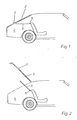
- 1 denotes the tailgate of a passenger car, which has a rear window 2.
- the cover plate 3 above the trunk 4 is articulated with its two front corners in a bearing 5 each.
- the bearings 5 enable the cover plate 3 to be pivoted into an approximately horizontal closed position (FIG. 1), an open position (FIG. 2) and the cover plate 3 to be removed.
- the bearing 5 is shown in FIGS. 3 to 9 in detail. It comprises a molded part 6, a receiving part 7, a bearing plate 8 and a helical spring arranged around a shaft screw 9 and a nut (not shown) which can be screwed onto the helical spring 9.
- the molded part 6 (see Fig. 3) is essentially wedge-shaped, i.e. it widens forward from its rear end aligned with the side wall of the vehicle, the widening part being covered by an upper wall 10.
- a guide slot 12 is formed in the side wall 11 and opens into a cylindrical opening 13 running transversely to the longitudinal axis of the molded part 6.
- Behind the cylindrical opening 13, seen in the longitudinal direction of the molded part 6, the side wall 11 of the molded part 6 is stepped towards the side wall of the vehicle and extends to an arm-shaped fastening section 14 of the molded part 6.
- a mounting opening 15 which can be closed by means of a cover 16 is provided.
- the molded part 6 is expediently designed as an injection molded part made of plastic.
- the cylindrical opening 13 in the molded part 6 serves to receive the receiving part 7 (see FIGS. 4 to 6).
- the receiving part 7 has a round front plate 17 with a guide flange 19 which is arranged on its edge 18 and extends in the axial direction and which slidably engages with the opening 13 stands. That is, the guide flange 19 extends in a circular shape from the edge 18 of the front plate 17 into the opening 13.
- a slot 20 extending up to its edge 18 is arranged in the central part of the front plate 17, ie running through its center.
- the slot 20 has a depth in its longitudinal direction which corresponds approximately to the diameter of the front plate 17, and widens in its front region, two end flanges 21 extending in the circumferential direction of the front plate 17 being provided at its front end.
- the slot 20 is essentially cuboid and is delimited by a stop wall 22 in the insertion direction of the cover plate 3, a rear wall 23 in the axial direction of the receiving part 7 and by an upper and lower wall 24, 25, and is in the region of the front plate 17 and the edge 18 open.
- the receiving part 7 On its rear side, the receiving part 7 has locking projections 26, the locking projections 26 being arranged on the rear of the rear wall 23 of the slot 20, extending from the edge 18 to the vicinity of the axis.
- the rear wall 23 of the slot 20 On the back of the rear wall 23 of the slot 20 there is also a shaft screw 9 which extends in the axial direction of the receiving part 7 and which serves to connect the receiving part 7 to the end shield 8 described below. Furthermore, the rear wall 23 in the region of the connecting wall 22 has a locking opening 27 into which a corresponding projection on the cover plate (not shown) can engage in order to prevent the cover plate from being unintentionally released.
- the bearing plate 8, which engages with the receiving part 7 in the assembled state and against the receiving part 7 is prestressed by means of a spring arranged on the shaft screw 9, has an essentially square bearing surface 28 with latching grooves 29 arranged on the front.
- the locking grooves 29 correspond to the locking projections 26 of the receiving part 7, and they can have any shape. In the illustrated embodiment, they extend in a star shape from the center of the bearing plate 8 to the outside, six locking grooves 29 being provided which can be brought into engagement with the two locking projections 26 on the receiving part 7, so that three locking positions are possible.
- the locking grooves 29 are arranged at an angular distance of about 60 °.
- the bearing surface 28 has a spring counter bearing surface 30 on its rear side, which is arranged around a central opening 31 in the bearing plate 8.
- the above-mentioned shaft screw extends through the opening 31.
- the bearing plate 8 is fastened with its fastening section 32 to the side wall of the vehicle or to the molded part 6. Then the receiving part 7 is arranged in the opening 13, its socket screw 9 extending through the central opening 31 in the bearing plate 8.
- the end shield 8 is pressed against the receiving part 7 by means of a helical spring which is attached to the shaft of the shank screw 9 and which is supported against the spring counter-bearing surface 30, the other end of the helical spring resting against a nut which can be screwed onto the shank screw 9.
- the pretension can be set as desired.
- the pre-assembled molded part 7 is screwed onto the side wall of the vehicle.
Abstract
Description
- Die Erfindung betrifft eine Lagerung für eine schwenkbare Abdeckplatte über dem Kofferraum von Kraftfahrzeugen mit einer in mehreren Raststellungen arretierbaren, mit einem Teil der Abdeckplatte in Eingriff stehenden Halterung gemäß dem Oberbegriff des Anspruchs 1.
- Um den Kofferraum zu vergrößern, haben sich bei Fahrzeugen mit einer Heckklappe verschiedene Systeme bewährt. Die meisten basieren darauf, daß die Rücksitzbank oder Teile derselben umgeklappt bzw. geschwenkt werden. Dabei ist es meist erforderlich, die den Kofferraum abdeckende Platte zu entfernen. Dies kann auch erforderlich werden, wenn die Rücksitzbank nicht umgeklappt werden soll, jedoch eine größere Ladehöhe des vorhandenen Kofferraums gewünscht wird.
- Zu diesem Zweck wurde in der DE-AS 26 47 104 vorgesehen, die Abdeckplatte schwenkbar in den Seitenwänden des Kofferraums befestigten Aufnahmeteilen zu lagern und durch ein Federelement zu sichern.
- Diese bekannte Lagerung ist auf der Seitenwand angeordnet. Beim Einschieben einer gelösten Abdeckplatte in die Lagerung muß der vordere Rand der Abdeckplatte mit den beiden Führungsschlitzen der Lagerung in Eingriff gebracht werden. Dies ist schwierig, da es erforderlich ist, um ein Verkanten zu vermeiden, die Abdeckplatte gleichförmig in die Schlitze der an den beiden Seitenwänden angeordneten Führung einzuschieben. Desweiteren beeinträchtigt die von den Seitenwänden vorstehende Halterung unter Umständen den Beladevorgang.
- Es ist daher Aufgabe der vorliegenden Erfindung, eine Halterung der eingangs genannten Art derart weiterzubilden, daß der Einschiebvorgang der Abdeckplatte erleichtert wird.
- Diese Aufgabe wird durch die in Anspruch 1 gekennzeichnete Erfindung gelöst, d.h. durch ein in der Wandverkleidung einer oder beider Seitenwände des Fahrzeugs mit dieser bzw. diesen abschließend angeordnetes Formteil, ein in dem Formteil drehbar angeordnetes Aufnahmeteil für den damit in Eingriff stehenden Teil der Abdeckplatte und ein mit dem Aufnahmeteil verrastbares und gegen dieses vorgespanntes stationär im Formteil angeordnetes Lagerschild, wobei das Formteil einen in Längsrichtung verlaufenden Führungsschlitz aufweist, der in eine querverlaufende, zylindrische Öffnung für das Aufnahmeteil mündet.
- Durch diese Anordnung wird in vorteilhafter Weise die eigentliche Lagerung in die Seitenwand des Fahrzeugs integriert, so daß die Abdeckplatte dicht an die Seitenwand herangeführt werden kann, wobei dennoch ein einfaches Lösen und Befestigen der Abdeckplatte möglich ist.
- Vorteilhafte Ausgestaltungen der Erfindung ergeben sich aus den Unteransprüchen.
- Dadurch, daß das Aufnahmeteil eine runde Frontplatte mit einem an ihrem Rand angeordneten, sich in Achsrichtung erstreckenden Führungsflansch, der mit der Wandung der Öffnung in gleitendem Eingriff steht, aufweist, wird in vorteilhafter Weise eine vollkommen geschlossene Anordnung der Halterung erreicht.
- In weiterer vorteilhafter Ausgestaltung der Erfindung ist vorgesehen, daß das Aufnahmeteil einen im mittleren Teil der Frontplatte angeordneten, sich bis zu ihrem Rand erstreckenden Schlitz aufweist, der sich in Achsrichtung von der Frontplatte nach hinten erstreckt. Die schlitzförmige Ausgestaltung der Halterung gestattet eine sehr einfache Konstruktion des Aufnahmeteils, so daß es kostengünstig herstellbar ist.
- Zweckmäßigerweise ist vorgesehen, daß der Schlitz im wesentlichen quaderförmig ausgebildet ist, durch eine Anschlagswand in Einschiebrichtung der Abdeckplatte, eine hintere Wand in Achsrichtung des Aufnahmeteils und durch eine obere und untere Wand begrenzt und im Bereich der Frontplatte und des Randes offen ist.
- Damit die Abdeckplatte verschiedene angehobene Stellungen einnehmen kann, ist vorgesehen, daß das Aufnahmeteil auf seiner Rückseite Rastvorsprünge aufweist.
- Zweckmäßigerweise sind die Rastvorsprünge auf der Rückseite der hinteren Wand des Schlitzes, sich vom Rand bis in die Nähe der Achse erstreckend, angeordnet.
- Zur Befestigung des Aufnahmeteils ist auf der Rückseite der hinteren Wand des Schlitzes eine sich in Achsrichtung erstreckende Schaftschraube angeordnet.
- Damit die in die Halterung eingeschobene Abdeckplatte nicht unbeabsichtigt aus dem Aufnahmeteil herausgezogen wird, weist die hintere Wand im Bereich der Anschlagswand eine Verriegelungsöffnung auf.
- Das Lagerschild weist in vorteilhafter Weise eine im wesentlichen quadratische Lagerfläche mit auf der Vorderseite angeordneten, den Rastvorsprüngen des Aufnahmeteils entsprechenden Rastnuten und einer mittleren Öffnung für die Schaftschraube des Aufnahmeteils sowie einen sich von der Lagerfläche erstreckenden Befestigungsabschnitt auf.
- Dies ermöglicht eine einfache konstruktive Ausgestaltung, die die erforderliche Festigkeit aufweist und dabei kostengünstig, z.B. mittels Spritzgießen aus Kunststoff, hergestellt werden kann.
- Zur Verspannung des Aufnahmeteils mit dem Lagerschild weist die Lagerfläche auf ihrer Rückseite eine Federgegenlagerfläche auf, gegen die sich eine auf der Schaftschraube angeordnete Schraubenfeder abstützt, die mit ihrem anderen Ende gegen eine auf die Schraube aufschraubbare Mutter anliegt.
- Wie bereits erwähnt, ist vorgesehen, daß das Aufnahmeteil, das Lagerschild und das Formteil als Spritzgußteile aus Kunststoff ausgebildet sind.
- Ein Ausführungsbeispiel der Erfindung ist in der Zeichnung dargestellt und wird im folgenden näher beschrieben. Es zeigen:
- Fig. 1 eine Seitenansicht des Heckteils eines Fließheck-Kraftfahrzeugs mit geschlossener Heckklappe;
- Fig. 2 das Fahrzeug nach Fig. 1 mit geöffneter Heckklappe und nach oben geschwenkter Abdeckplatte;
- Fig. 3 eine perspektivische Ansicht des Formteils;
- Fig. 4 eine Ansicht des Aufnahmeteils von hinten;
- Fig. 5 eine seitliche Schnittansicht des Aufnahmeteils längs der Linie V-V in Fig. 4;
- Fig. 6 eine Ansicht des Aufnahmeteils von vorne;
- Fig. 7 eine Ansicht des Lagerschildes von vorne;
- Fig. 8 eine Seitenansicht des Lagerschildes; und
- Fig. 9 eine Ansicht des Lagerschildes von hinten.
- In der Zeichnung ist mit 1 die Heckklappe eines Personenwagens bezeichnet, die eine Heckscheibe 2 aufweist. Die Abdeckplatte 3 über dem Kofferraum 4 ist mit ihren beiden vorderen Ecken in je einem Lager 5 angelenkt. Die Lager 5 ermöglichen das Schwenken der Abdeckplatte 3 in eine etwa waagerechte Schließstellung (Fig. 1), eine Offenstellung (Fig. 2) sowie ein Herausnehmen der Abdeckplatte 3.
- Die Lagerung 5 ist in den Fig. 3 bis 9 im einzelnen dargestellt. Sie umfaßt ein Formteil 6, ein Aufnahmeteil 7, ein Lagerschild 8 sowie eine um eine Schaftschraube 9 angeordnete Schraubenfeder und eine auf die Schraubenfeder 9 aufschraubbare Mutter (nicht dargestellt).
- Das Formteil 6 (siehe Fig. 3) ist im wesentlichen keilförmig ausgebildet, d.h. es verbreitert sich von seinem hinteren, mit der Seitenwand des Fahrzeugs fluchtenden Ende nach vorne, wobei der sich verbreiternde Teil von einer oberen Wand 10 abgedeckt wird. In der Seitenwand 11 ist ein Führungsschlitz 12 ausgebildet, der in eine quer zur Längsachse des Formteils 6 verlaufende zylindrische Öffnung 13 mündet. Hinter der zylindrischen Öffnung 13, in Längsrichtung des Formteils 6 gesehen, ist die Seitenwand 11 des Formteils 6 zur Seitenwand des Fahrzeugs hin abgestuft und erstreckt sich bis zu einem armförmigen Befestigungsabschnitt 14 des Formteils 6. Im Bereich der zylinderförmigen Öffnung 13 ist in der oberen Wand 10 eine mittels einem Deckel 16 verschließbare Montageöffnung 15 vorgesehen. Das Formteil 6 ist zweckmäßigerweise als Spritzgußteil aus Kunststoff ausgebildet.
- Die zylindrische Öffnung 13 im Formteil 6 dient zur Aufnahme des Aufnahmeteils 7 (siehe Fig. 4 bis 6). Das Aufnahmeteil 7 weist eine runde Frontplatte 17 mit einem an ihrem Rand 18 angeordneten, sich in Achsrichtung erstreckenden Führungsflansch 19 auf, der mit der Öffnung 13 in gleitendem Eingriff steht. D.h., der Führungsflansch 19 erstreckt sich kreisringförmig von dem Rand 18 der Frontplatte 17 in die Öffnung 13. Im mittleren Teil der Frontplatte 17, d.h. durch ihren Mittelpunkt verlaufend, ist ein sich bis zu ihrem Rand 18 erstreckender Schlitz 20 angeordnet. Der Schlitz 20 weist in seiner Längsrichtung eine Tiefe auf, die in etwa dem Durchmesser der Frontplatte 17 entspricht, und verbreitert sich in seinem vorderen Bereich, wobei an seinem vorderen Ende zwei sich in Umfangsrichtung der Frontplatte 17 erstreckende Abschlußflansche 21 vorgesehen sind.
- Der Schlitz 20 ist im wesentlichen quaderförmig ausgebildet und durch eine Anschlagswand 22 in Einschiebrichtung der Abdeckplatte 3, eine hintere Wand 23 in Achsrichtung des Aufnahmeteils 7 und durch eine obere und untere Wand 24, 25 begrenzt, und ist im Bereich der Frontplatte 17 und des Randes 18 offen.
- Auf seiner Rückseite weist das Aufnahmeteil 7 Rastvorsprünge 26 auf, wobei die Rastvorsprünge 26 auf der Rückseite der hinteren Wand 23 des Schlitzes 20, sich vom Rand 18 bis in die Nähe der Achse erstreckend, angeordnet sind.
- Auf der Rückseite der hinteren Wand 23 des Schlitzes 20 ist weiter eine sich in Achsrichtung des Aufnahmeteils 7 erstreckende Schaftschraube 9 angeordnet, die zur Verbindung des Aufnahmeteils 7 mit dem weiter unten beschriebenen Lagerschild 8 dient. Weiter weist die hintere Wand 23 im Bereich der Anschlußwand 22 eine Verriegelungsöffnung 27 auf, in die ein entsprechender Vorsprung an der Abdeckplatte (nicht dargestellt) eingreifen kann, um ein unbeabsichtigtes Lösen der Abdeckplatte zu verhindern.
- Das Lagerschild 8, das mit dem Aufnahmeteil 7 im zusammengebauten Zustand in Eingriff tritt und gegen das Aufnahmeteil 7 mittels einer auf der Schaftschraube 9 angeordneten Feder vorgespannt ist, weist eine im wesentlichen quadratische Lagerfläche 28 mit auf der Vorderseite angeordneten Rastnuten 29 auf. Die Rastnuten 29 (siehe Fig. 7) entsprechen den Rastvorsprüngen 26 des Aufnahmeteils 7, wobei sie irgendeine beliebige Form haben können. Im dargestellten Ausführungsbeispiel erstrecken sie sich sternförmig vom Mittelpunkt des Lagerschildes 8 nach außen, wobei sechs Rastnuten 29 vorgesehen sind, die mit den zwei Rastvorsprüngen 26 am Aufnahmeteil 7 in Eingriff bringbar sind, so daß drei Raststellungen möglich sind. Dabei sind die Rastnuten 29 in einem winkligen Abstand von etwa 60° angeordnet.
- Zur Abstützung der Schraubenfeder weist die Lagerfläche 28 auf ihrer Rückseite eine Federgegenlagerfläche 30 auf, die rings um eine mittlere Öffnung 31 in dem Lagerschild 8 angeordnet ist. Durch die Öffnung 31 erstreckt sich die oben erwähnte Schaftschraube.
- Zum Zusammenbau der Lagerung wird das Lagerschild 8 mit seinem Befestigungsabschnitt 32 an der Seitenwand des Fahrzeugs oder an dem Formteil 6 befestigt. Dann wird das Aufnahmeteil 7 in der Öffnung 13 angeordnet, wobei sich seine Schaftschraube 9 durch die mittlere Öffnung 31 im Lagerschild 8 erstreckt. Mittels einer auf dem Schaft der Schaftschraube 9 angebrachten Schraubenfeder, die sich gegen die Federgegenlagerfläche 30 abstützt, wird das Lagerschild 8 gegen das Aufnahmeteil 7 gedrückt, wobei das andere Ende der Schraubenfeder gegen eine auf die Schaftschraube 9 aufschraubbare Mutter anliegt. Durch entsprechendes Anziehen der Mutter kann die Vorspannung in gewünschter Weise eingestellt werden. Das so vormontierte Formteil 7 wird an der Seitenwand des Fahrzeugs angeschraubt.
- Zum Nachstellen oder Erneuern der Lagerung ist es nicht erforderlich, das Formteil 6 vom Fahrzeug zu lösen, da ebenfalls ein Zugang zur Lagerung durch die in der oberen Wand 10 des Formteils 6 vorgesehene Montageöffnung 15 möglich ist.
Claims (11)
Applications Claiming Priority (2)
| Application Number | Priority Date | Filing Date | Title |
|---|---|---|---|
| DE3808083 | 1988-03-11 | ||
| DE3808083A DE3808083C1 (de) | 1988-03-11 | 1988-03-11 |
Publications (2)
| Publication Number | Publication Date |
|---|---|
| EP0332059A1 true EP0332059A1 (de) | 1989-09-13 |
| EP0332059B1 EP0332059B1 (de) | 1991-01-16 |
Family
ID=6349449
Family Applications (1)
| Application Number | Title | Priority Date | Filing Date |
|---|---|---|---|
| EP89103711A Expired - Lifetime EP0332059B1 (de) | 1988-03-11 | 1989-03-03 | Lagerung für eine schwenkbare Abdeckplatte |
Country Status (3)
| Country | Link |
|---|---|
| EP (1) | EP0332059B1 (de) |
| DE (2) | DE3808083C1 (de) |
| ES (1) | ES2019708B3 (de) |
Cited By (4)
| Publication number | Priority date | Publication date | Assignee | Title |
|---|---|---|---|---|
| US6394002B1 (en) | 1999-06-11 | 2002-05-28 | Sai Automotive Sommer Industrie | Device for holding and articulating a removable rear shelf of a motor vehicle |
| EP2492146A1 (de) * | 2011-02-25 | 2012-08-29 | Saab Automobile Ab | Automatisches Paketregal |
| CN102933426A (zh) * | 2010-05-21 | 2013-02-13 | 株式会社利富高 | 后置物板的铰链结构 |
| EP2716499A1 (de) * | 2012-10-05 | 2014-04-09 | Faurecia Innenraum Systeme GmbH | Heckanordnung eines Kraftfahrzeugs und zugehöriges Kraftfahrzeug |
Families Citing this family (3)
| Publication number | Priority date | Publication date | Assignee | Title |
|---|---|---|---|---|
| DE19735439A1 (de) * | 1997-08-16 | 1999-02-18 | Volkswagen Ag | Anordnung mit einer Gepäckraumabdeckung in einem Fahrzeug |
| DE19856741C2 (de) * | 1998-12-09 | 2001-02-01 | Baumeister & Ostler Gmbh Co | Laderaumabdeckung bzw. Hutablage mit beweglichen Eckstücken |
| DE102006052598B4 (de) * | 2006-11-08 | 2022-06-09 | Volkswagen Ag | Abdeckvorrichtung für einen Gepäckraum eines Kraftfahrzeuges |
Citations (2)
| Publication number | Priority date | Publication date | Assignee | Title |
|---|---|---|---|---|
| DE7808131U1 (de) * | 1978-03-17 | 1978-06-29 | Eberhardt Kraftfahrzeug Gmbh & Co Kg, 7900 Ulm | Befestigungsvorrichtung fuer einen innerhalb eines fahrgastraumes eines kraftfahrzeuges anzubringenden gegenstand |
| DE2647104B2 (de) * | 1976-10-19 | 1981-04-09 | Audi Nsu Auto Union Ag, 7107 Neckarsulm | Lagerung für eine schwenkbare Abdeckplatte über dem Kofferraum von Kraftfahrzeugen |
-
1988
- 1988-03-11 DE DE3808083A patent/DE3808083C1/de not_active Expired
-
1989
- 1989-03-03 ES ES89103711T patent/ES2019708B3/es not_active Expired - Lifetime
- 1989-03-03 DE DE8989103711T patent/DE58900043D1/de not_active Expired - Fee Related
- 1989-03-03 EP EP89103711A patent/EP0332059B1/de not_active Expired - Lifetime
Patent Citations (2)
| Publication number | Priority date | Publication date | Assignee | Title |
|---|---|---|---|---|
| DE2647104B2 (de) * | 1976-10-19 | 1981-04-09 | Audi Nsu Auto Union Ag, 7107 Neckarsulm | Lagerung für eine schwenkbare Abdeckplatte über dem Kofferraum von Kraftfahrzeugen |
| DE7808131U1 (de) * | 1978-03-17 | 1978-06-29 | Eberhardt Kraftfahrzeug Gmbh & Co Kg, 7900 Ulm | Befestigungsvorrichtung fuer einen innerhalb eines fahrgastraumes eines kraftfahrzeuges anzubringenden gegenstand |
Cited By (7)
| Publication number | Priority date | Publication date | Assignee | Title |
|---|---|---|---|---|
| US6394002B1 (en) | 1999-06-11 | 2002-05-28 | Sai Automotive Sommer Industrie | Device for holding and articulating a removable rear shelf of a motor vehicle |
| CN102933426A (zh) * | 2010-05-21 | 2013-02-13 | 株式会社利富高 | 后置物板的铰链结构 |
| CN102933426B (zh) * | 2010-05-21 | 2015-02-11 | 株式会社利富高 | 后置物板的铰链结构 |
| EP2492146A1 (de) * | 2011-02-25 | 2012-08-29 | Saab Automobile Ab | Automatisches Paketregal |
| EP2716499A1 (de) * | 2012-10-05 | 2014-04-09 | Faurecia Innenraum Systeme GmbH | Heckanordnung eines Kraftfahrzeugs und zugehöriges Kraftfahrzeug |
| WO2014053630A1 (fr) * | 2012-10-05 | 2014-04-10 | Faurecia Innenraum Systeme Gmbh | Ensemble arrière de véhicule automobile et véhicule automobile associé |
| US9598020B2 (en) | 2012-10-05 | 2017-03-21 | Faurecia Innenraum Systeme Gmbh | Rear assembly for a motor vehicle and associated motor vehicle |
Also Published As
| Publication number | Publication date |
|---|---|
| EP0332059B1 (de) | 1991-01-16 |
| DE3808083C1 (de) | 1989-04-13 |
| DE58900043D1 (de) | 1991-02-21 |
| ES2019708B3 (es) | 1991-07-01 |
Similar Documents
| Publication | Publication Date | Title |
|---|---|---|
| DE19640354C2 (de) | Kofferraumkonstruktion | |
| DE102006041734A1 (de) | Vorrichtung zur Befestigung einer Airbageinheit in einer Baugruppe eines Kraftfahrzeugs, insbesondere in einem Lenkrad, durch Verrasten | |
| EP0981465B1 (de) | In ein fahrzeug einbaubarer behälter zur brillenablage | |
| DE4334721B4 (de) | Scheinwerfer für Fahrzeuge | |
| DE102018126565B4 (de) | Scharnier für ein staufach im laderaum eines fahrzeugs | |
| DE19824085B4 (de) | Scheinwerferreinigungsanlage mit einer Hubdüsenanordnung | |
| DE3723984A1 (de) | Deckelrastmechanismus fuer eine kraftfahrzeug-schalttafelfeld-einrichtung | |
| EP0332059B1 (de) | Lagerung für eine schwenkbare Abdeckplatte | |
| EP0713806A1 (de) | Verschluss-/Haltevorrichtung für ein Kfz-Verkleidungsteil | |
| DE3318740C2 (de) | ||
| DE19521592C1 (de) | Aufnahmevorrichtung für Geräte und/oder Gegenstände im Fahrgastraum eines Kraftfahrzeugs | |
| DE102008018738B4 (de) | Fahrzeugseitige Kupplungsbaugruppe einer Anhängerkupplung | |
| DE60114493T2 (de) | Haltevorrichtung für eine Bowdenzughülle | |
| EP1398219A2 (de) | Vorrichtung zur Unterbringung eines elektrischen Geräts im Innenraum eines Kraftfahrzeugs | |
| DE102009058570A1 (de) | Vorrichtung zur drehbaren Lagerung einer Hutablage | |
| EP0062229B1 (de) | Gegenlagerböckchen für Fahrzeugsonnenblenden | |
| EP1876056A2 (de) | Laderaumabdeckeinrichtung und Kraftfahrzeug mit Laderaumabdeckeinrichtung | |
| DE102011120090B4 (de) | Hutablage für ein Kraftfahrzeug | |
| EP1566309B1 (de) | Transportbehälter für Fahrzeuge für den sitzlehnen- oder kofferraumwandseitigen Einbau in Personenkraftwagen | |
| DE102016207179B3 (de) | Kraftfahrzeug-Tür und Türgriffsystem hierfür | |
| DE60022924T2 (de) | Innenteil einer Fahrzeugtür, korrespondierende Tür und Verfahren für den Zusammenbau einer solchen Tür | |
| DE4307088C1 (de) | Aufnahmevorrichtung für Geräte und/oder Gegenstände im Fahrgastraum eines Kraftfahrzeugs | |
| EP1516562B1 (de) | Vorrichtung zum Verstellen der Neigung eines Auszugs | |
| DE2710569A1 (de) | Innenrueckblickspiegel fuer fahrzeuge | |
| DE2647104B2 (de) | Lagerung für eine schwenkbare Abdeckplatte über dem Kofferraum von Kraftfahrzeugen |
Legal Events
| Date | Code | Title | Description |
|---|---|---|---|
| PUAI | Public reference made under article 153(3) epc to a published international application that has entered the european phase |
Free format text: ORIGINAL CODE: 0009012 |
|
| 17P | Request for examination filed |
Effective date: 19890303 |
|
| AK | Designated contracting states |
Kind code of ref document: A1 Designated state(s): DE ES FR GB IT |
|
| 17Q | First examination report despatched |
Effective date: 19900209 |
|
| ITF | It: translation for a ep patent filed |
Owner name: DE DOMINICIS & MAYER S.R.L. |
|
| GRAA | (expected) grant |
Free format text: ORIGINAL CODE: 0009210 |
|
| AK | Designated contracting states |
Kind code of ref document: B1 Designated state(s): DE ES FR GB IT |
|
| GBT | Gb: translation of ep patent filed (gb section 77(6)(a)/1977) | ||
| REF | Corresponds to: |
Ref document number: 58900043 Country of ref document: DE Date of ref document: 19910221 |
|
| ET | Fr: translation filed | ||
| PLBE | No opposition filed within time limit |
Free format text: ORIGINAL CODE: 0009261 |
|
| STAA | Information on the status of an ep patent application or granted ep patent |
Free format text: STATUS: NO OPPOSITION FILED WITHIN TIME LIMIT |
|
| 26N | No opposition filed | ||
| REG | Reference to a national code |
Ref country code: GB Ref legal event code: IF02 |
|
| PGFP | Annual fee paid to national office [announced via postgrant information from national office to epo] |
Ref country code: DE Payment date: 20050331 Year of fee payment: 17 |
|
| PGFP | Annual fee paid to national office [announced via postgrant information from national office to epo] |
Ref country code: ES Payment date: 20060306 Year of fee payment: 18 |
|
| PGFP | Annual fee paid to national office [announced via postgrant information from national office to epo] |
Ref country code: FR Payment date: 20060317 Year of fee payment: 18 |
|
| PGFP | Annual fee paid to national office [announced via postgrant information from national office to epo] |
Ref country code: GB Payment date: 20060322 Year of fee payment: 18 |
|
| PGFP | Annual fee paid to national office [announced via postgrant information from national office to epo] |
Ref country code: IT Payment date: 20060331 Year of fee payment: 18 |
|
| PG25 | Lapsed in a contracting state [announced via postgrant information from national office to epo] |
Ref country code: DE Free format text: LAPSE BECAUSE OF NON-PAYMENT OF DUE FEES Effective date: 20061003 |
|
| GBPC | Gb: european patent ceased through non-payment of renewal fee |
Effective date: 20070303 |
|
| REG | Reference to a national code |
Ref country code: FR Ref legal event code: ST Effective date: 20071130 |
|
| PG25 | Lapsed in a contracting state [announced via postgrant information from national office to epo] |
Ref country code: GB Free format text: LAPSE BECAUSE OF NON-PAYMENT OF DUE FEES Effective date: 20070303 |
|
| REG | Reference to a national code |
Ref country code: ES Ref legal event code: FD2A Effective date: 20070305 |
|
| PG25 | Lapsed in a contracting state [announced via postgrant information from national office to epo] |
Ref country code: ES Free format text: LAPSE BECAUSE OF NON-PAYMENT OF DUE FEES Effective date: 20070305 Ref country code: FR Free format text: LAPSE BECAUSE OF NON-PAYMENT OF DUE FEES Effective date: 20070402 |
|
| PG25 | Lapsed in a contracting state [announced via postgrant information from national office to epo] |
Ref country code: IT Free format text: LAPSE BECAUSE OF NON-PAYMENT OF DUE FEES Effective date: 20070303 |