EP0332045A2 - Appareil de commande sans contact d'installations sanitaires - Google Patents
Appareil de commande sans contact d'installations sanitaires Download PDFInfo
- Publication number
- EP0332045A2 EP0332045A2 EP89103619A EP89103619A EP0332045A2 EP 0332045 A2 EP0332045 A2 EP 0332045A2 EP 89103619 A EP89103619 A EP 89103619A EP 89103619 A EP89103619 A EP 89103619A EP 0332045 A2 EP0332045 A2 EP 0332045A2
- Authority
- EP
- European Patent Office
- Prior art keywords
- detection unit
- remote control
- control unit
- operating mode
- information
- Prior art date
- Legal status (The legal status is an assumption and is not a legal conclusion. Google has not performed a legal analysis and makes no representation as to the accuracy of the status listed.)
- Granted
Links
Images
Classifications
-
- G—PHYSICS
- G01—MEASURING; TESTING
- G01S—RADIO DIRECTION-FINDING; RADIO NAVIGATION; DETERMINING DISTANCE OR VELOCITY BY USE OF RADIO WAVES; LOCATING OR PRESENCE-DETECTING BY USE OF THE REFLECTION OR RERADIATION OF RADIO WAVES; ANALOGOUS ARRANGEMENTS USING OTHER WAVES
- G01S17/00—Systems using the reflection or reradiation of electromagnetic waves other than radio waves, e.g. lidar systems
- G01S17/88—Lidar systems specially adapted for specific applications
-
- G—PHYSICS
- G01—MEASURING; TESTING
- G01S—RADIO DIRECTION-FINDING; RADIO NAVIGATION; DETERMINING DISTANCE OR VELOCITY BY USE OF RADIO WAVES; LOCATING OR PRESENCE-DETECTING BY USE OF THE REFLECTION OR RERADIATION OF RADIO WAVES; ANALOGOUS ARRANGEMENTS USING OTHER WAVES
- G01S7/00—Details of systems according to groups G01S13/00, G01S15/00, G01S17/00
- G01S7/003—Transmission of data between radar, sonar or lidar systems and remote stations
-
- G—PHYSICS
- G01—MEASURING; TESTING
- G01S—RADIO DIRECTION-FINDING; RADIO NAVIGATION; DETERMINING DISTANCE OR VELOCITY BY USE OF RADIO WAVES; LOCATING OR PRESENCE-DETECTING BY USE OF THE REFLECTION OR RERADIATION OF RADIO WAVES; ANALOGOUS ARRANGEMENTS USING OTHER WAVES
- G01S7/00—Details of systems according to groups G01S13/00, G01S15/00, G01S17/00
- G01S7/48—Details of systems according to groups G01S13/00, G01S15/00, G01S17/00 of systems according to group G01S17/00
- G01S7/497—Means for monitoring or calibrating
Definitions
- operating mode and “operating parameters” are used below to characterize the functioning of such devices. These are defined as follows:
- Operating mode is understood to mean the use of the device in a purpose that requires a very specific, logical sequence of the output pulses. This is particularly the case if the detection unit is to be used to control different sanitary fittings (eg wash basin fittings, urinals, showers, etc.). Each of these operating modes requires a certain logic in the correlation between the detection of the user and the time of occurrence of the activation of the sanitary fitting used pulses, where appropriate suitable delay and time elements are used.
- sanitary fittings eg wash basin fittings, urinals, showers, etc.
- Operating parameters are understood to mean those internal variables which can occur within the same operating mode of the device.
- the fundamental frequency with which the transmitter is operated is considered.
- the pulse duration and the pulse sequence with which the transmitter emits radiation in the fundamental frequency must be distinguished from the fundamental frequency. In general, radiation is not continuously emitted to save electricity.
- Further operating parameters that may be of interest are, for example, the state of charge of a battery used as a current source, the sensitivity (detection range) of the detection unit or the position of the actuator which is acted upon by the output signals of the detection unit.
- a device for the contactless control of a sanitary fitting of the type mentioned is the subject of the unpublished patent application P 37 35 854.5.
- the main idea here is that the opening of the Actuator, which leads to a flow of water, must then be prevented when the state of charge of the battery serving as a power source is no longer sufficient to close.
- the older patent application suggests the use of a remote control unit, which can enter into dialogue with the actual detection unit.
- the mode of operation should be such that information-carrying impulses are only emitted by the detection unit when the presence of a user is determined in the detection area of the detection unit.
- the object of the present invention is to provide a device for the contactless control of a sanitary fitting of the type mentioned in such a way that it is vandal-proof, suitable for all conceivable operating modes and can be easily and easily set on site to the required operating parameters and at the same time the information about it Operating mode and / or the operating parameters easily accessible.
- the device for the contactless control of a sanitary fitting is designed as a "unit device" which is fundamentally suitable for all operating modes. These operating modes are stored in an internal memory and can be called up using appropriate commands.
- the electronic components can be completely encapsulated; Manual control elements are no longer required, since according to the invention all information flows about the radiation exchanged between the detection unit and the remote control unit take place through the same windows of the detection unit that are used to detect a user in normal operation.
- the operating mode of the detection unit that is desired in each case is called up by pressing a button on the remote control unit. Adjustment and adjustment work also takes place via radiation which is emitted by the remote control unit and is correctly understood by the detection unit.
- the detection unit on the radiation path gives all information about the current operating mode and the operating parameters to the outside. According to the invention, this does not take place until a user has entered the detection area of the detection unit.
- the radiation emitted by the transmitter of the detection unit it is possible for the radiation emitted by the transmitter of the detection unit to continuously carry information about the operating mode and / or the operating parameters of the detection unit.
- the circuitry is lowest with this design; For the function of the radiation emitted by the transmitter of the detection unit when a user is detected, it is completely irrelevant whether this radiation also (continuously) carries additional information.
- the radiation emitted by the transmitter of the detection unit is only provided with information about the operating mode and / or the operating parameters if a corresponding command has previously been transmitted from the remote control unit to the detection unit. In any case, it is not necessary for the transmission of information that a user be registered in the detection area beforehand.
- the information about the operating mode and the operating parameters of the detection unit can be called up and queried individually by a corresponding command from the remote control unit.
- the remote control unit should have a display on which the information transmitted by the detection unit can be made visible.
- the remote control unit should have an input field on which the various commands can be entered manually.
- the display can also be used to check the commands entered.
- the devices for the contactless control of a sanitary fitting work with infrared light as radiation.
- the overall arrangement voltage can be made particularly vandal-proof in that the front panel of the detection unit, which contains the entrance window and the exit window, is made of a material which is transparent in the infrared range, but impermeable in the range of visible light, and no openings which are visible from the outside, in particular also not in the zone of Entry window and the exit window.
- visible optical windows have proven to be special starting points for willful destruction in the past. Such windows are no longer recognizable in the device according to the invention in the embodiment according to claim 7.
- the overall construction becomes particularly simple if the front plate is shaped as a lens in the region of the entry window and the exit window. Additional imaging elements are then no longer required.
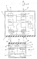
- the device for contactless control of a sanitary fitting shown in the drawing comprises a detection unit 1 and a remote control unit 2.
- the detection unit 1 is completely encapsulated in a housing 2, that is to say in particular it has no external, manually operated operating or setting elements. All adjustment, operating or programming processes are carried out without contact in a manner to be described.
- the side of the housing 3 facing the user is formed by a front plate 4, which consists of a special plastic material. This material is permeable to infrared, but not to visible light. In this way, it is not possible to see where from outside the front panel 4 is the entrance window 5 or the exit window 6 for the infrared radiation used for detection. This feature also contributes to the avoidance of willful destruction, since often the recognizable optical entry and exit windows of known fittings are made the target of willful damage.
- the plastic material of the front plate 4 is shaped as a lens in the area of the inlet or outlet opening 5, 6, so that additional optical imaging elements can be dispensed with.
- the infrared light entering through the entrance window 5 of the front plate 4 of the housing 3 first strikes a receiver 7, which in a known manner contains a receiving diode and a suitable amplifier for the signal generated by the receiving diode.
- the output signal of the receiver 7 is fed to a decoding circuit 8, the function of which is explained in detail below.
- the output of the decoding circuit 8 is connected to an input of a control circuit 9 which has access to a memory 10.
- the control circuit 9 generates output signals, which will be supplied to a driver 11, in a manner to be described below.
- the output of the driver 11 is connected to a socket 12 to which the actuator 13 of the sanitary fitting to be controlled can be connected.
- a clock 14 which pulses with a certain fundamental frequency in a certain outputs th clock sequence to a coding circuit 15.
- the clock 14 can be influenced by the control circuit 9 in a manner which will also be explained and for this purpose is connected to the latter via a line.
- the coding circuit 15 also receives commands from the control circuit 9 and imprints a specific coding on the pulses emitted by the clock generator 14. This coding can in principle take place in any form that is suitable for the transmission of information.
- the pulses coded by the coding circuit 15 are sent to a transmitter 16, in which suitable preamplifiers and a transmitting diode are contained in a known manner.
- the light generated by the transmitter diode is then emitted via the exit window 6 through the front panel 4.
- the "basic function" of the circuit arrangement described is essentially the same as that of known devices which contain no coding circuit 15, no decoding circuit 8 and no memory 10: the clock generator 14 generates pulses which are converted by the transmitter 16 into corresponding light pulses. If a user is within the detection range of the detection unit 1, light reflected on him reaches the receiver 7 through the entrance window 5.
- the control circuit processing the output signal of the receiver 7 generates an output pulse or an output pulse sequence with a predetermined time sequence, which amplified by the driver 11 and delivered to the actuator 13 of the sanitary fitting.
- the coding circuit 15 additionally contained in the device described here, the decoding circuit 8 and the memory 10 serve for dialogue with the remote control unit 2, as will become clear below.
- the remote control unit 2 also encapsulated in a housing 17, comprises various circuits that are required for querying information from the detection unit 1 or for programming the detection unit 1. In detail, it is a receiver 18 which is followed by a decoding circuit 19. The information contained in the decoded signal is shown on a display 20.
- the transmission branch of the remote control unit 2 comprises an input field 21 with various keys, by means of which various desired functions can be called up in suitable programming.
- the functions entered can, if necessary, be made visible on the display 20 for checking purposes.
- the output signal of the input field 21 is converted via a coding circuit 22 into a suitably coded pulse sequence which is then sent to a transmitter 23.
- Transmitter 23 and receiver 18 of remote control unit 2 can in principle be constructed similarly to transmitter 16 and receiver 7 of detection unit 1. Like these, receiver 18 and transmitter 23 of remote control unit 2 are at an entry window 25 and an exit window 26 of a front panel 24 attached, which consists of infrared light-permeable plastic material. Again, this is shaped into a lens in the area of the entry window 25 and the exit window 26.
- the remote control unit 2 and the detection unit 1 can now enter into dialogue in the following manner by exchanging information contained in the coding of the light transmitted between them in both directions:
- the detection unit 1 described above is to be used as a so-called "unit device”, should be used for a wide variety of operating modes and operating parameters.
- the required pulse sequences and the associated codes are stored in the sub-memories A, B, C of the memory 10 in the detection unit 1.
- the clock generator 14 of the detection unit 1 sends out pulses with a certain basic frequency, with a certain width and with a certain repetition frequency in the usual way.
- Information about the operating parameters of interest and the operating mode are impressed on these pulses in the coding circuit 15.
- the transmission light which is emitted by the transmitter 16 thus continuously contains information that the detection unit is operating in operating mode A (for example urinal), that the battery 27 is in a good state of charge, and that the clock generator is operating at a specific fundamental frequency. Additional information can relate, for example (when using suitable sensors), to the position of the actuator 13.
- the additional information broadcast by the transmitter 16 remains unused.
- the light reflected by the user, which strikes the receiver 7, also carries the codes produced by the coding circuit 15; however, these do not trigger any function in the decoding circuit 8.
- the way in which the detection unit 1 is used thus corresponds completely to what is known.
- the remote control unit 2 is brought close to the detection unit 1.
- the distance of the remote control unit 2 from the detection unit 1 can be so large that the actuator 13 is not actuated by the reflection on the remote control unit 2 or the operator.
- the light signals which the receiver 18 of the remote control unit 2 receives are decoded in the decoding circuit 19.
- the information contained is then shown on the display 20.
- the basic frequency at which the clock generator 14 operates, the operating mode (e.g. urinal) or the state of charge of the battery 27 can be read.
- the decoding circuit 8 in the detection unit 1 determines that the received light radiation contains a specific command. It causes the control circuit 9 to execute this command. If, for example, the command entered via the input field 21 affects the change to operating mode B (e.g. shower), the decoding circuit 8 gives the control circuit 9 the impulse to read out the sub-memory B from the memory 10 and to output pulse sequences adapted to this operating mode to the driver 11 .
- operating mode B e.g. shower
- Another command that can be given to the detection unit 1 via the input field 21 relates to the fundamental frequency at which the clock generator 14 operates.
- the setting of the basic frequency "on site" can be important if several detection units 1 are to be operated next to one another and independently of one another in a single room. By selecting different basic frequencies, mutual influences can be avoided in a known manner.
- a third group of commands which can be transmitted to the detection unit 1 via the input field 21 of the remote control unit 2, relates to the sensitivity of the detection unit 1. This is synonymous with the spatial detection range in which the detection unit 1 responds. This must also be able to be adapted to the respective circumstances on site.
- the duration of the individual pulses or the pauses between them can be set individually in the individual operating modes.
- the transmitter 16 of the detection unit 1 sent signals at all times which contained all the information about the operating mode and the operating parameters at the same time.
- the arrangement can also be made such that the information in question is impressed on the transmission light of the detection unit 1 only at certain times, which are determined by a pulse from the remote control unit 2.
- the operating mode and operating parameters can also be queried individually if necessary.
- the battery 27 was integrated in the housing 3 of the detection unit 1, this can also be removed from the housing, which can be useful when replacing the battery.
Landscapes
- Engineering & Computer Science (AREA)
- Computer Networks & Wireless Communication (AREA)
- Physics & Mathematics (AREA)
- Radar, Positioning & Navigation (AREA)
- Remote Sensing (AREA)
- General Physics & Mathematics (AREA)
- Electromagnetism (AREA)
- Selective Calling Equipment (AREA)
- Geophysics And Detection Of Objects (AREA)
- Sanitary Device For Flush Toilet (AREA)
- Absorbent Articles And Supports Therefor (AREA)
- Toilet Supplies (AREA)
- Coupling Device And Connection With Printed Circuit (AREA)
- Cookers (AREA)
- Domestic Plumbing Installations (AREA)
Priority Applications (1)
| Application Number | Priority Date | Filing Date | Title |
|---|---|---|---|
| AT89103619T ATE92641T1 (de) | 1988-03-08 | 1989-03-02 | Einrichtung zur beruehrungslosen steuerung einer sanitaerarmatur. |
Applications Claiming Priority (2)
| Application Number | Priority Date | Filing Date | Title |
|---|---|---|---|
| DE3807484A DE3807484C1 (fr) | 1988-03-08 | 1988-03-08 | |
| DE3807484 | 1988-03-08 |
Publications (3)
| Publication Number | Publication Date |
|---|---|
| EP0332045A2 true EP0332045A2 (fr) | 1989-09-13 |
| EP0332045A3 EP0332045A3 (en) | 1990-06-20 |
| EP0332045B1 EP0332045B1 (fr) | 1993-08-04 |
Family
ID=6349100
Family Applications (1)
| Application Number | Title | Priority Date | Filing Date |
|---|---|---|---|
| EP89103619A Expired - Lifetime EP0332045B1 (fr) | 1988-03-08 | 1989-03-02 | Appareil de commande sans contact d'installations sanitaires |
Country Status (4)
| Country | Link |
|---|---|
| EP (1) | EP0332045B1 (fr) |
| AT (1) | ATE92641T1 (fr) |
| DE (2) | DE3807484C1 (fr) |
| ES (1) | ES2047591T3 (fr) |
Cited By (14)
| Publication number | Priority date | Publication date | Assignee | Title |
|---|---|---|---|---|
| AU619415B2 (en) * | 1989-08-10 | 1992-01-23 | Munt & Jolly Pty. Ltd. | Computer controlled flushing system |
| EP0687778A1 (fr) * | 1994-06-10 | 1995-12-20 | Friedrich Grohe Aktiengesellschaft | Dispositif de commande de robinets d'eau |
| EP0826982A1 (fr) * | 1996-08-27 | 1998-03-04 | Geberit Technik Ag | Dispositif pour commander sans contact une armature sanitaire |
| US6639209B1 (en) | 2000-10-24 | 2003-10-28 | Synpase, Inc. | Method of automatic standardized calibration for infrared sensing device |
| US6707030B1 (en) | 2000-10-24 | 2004-03-16 | Synapse, Inc. | System and method of automatic dynamic calibration for infrared sensing device |
| US6768103B2 (en) | 2000-10-24 | 2004-07-27 | The Chicago Faucet Company | System and method of automatic dynamic calibration for infrared sensing device |
| US6770869B2 (en) | 2000-10-24 | 2004-08-03 | The Chicago Faucet Company | Method of automatic standardized calibration for infrared sensing device |
| EP1490739A2 (fr) * | 2002-03-28 | 2004-12-29 | Celec Conception electronique en Abrege Celec | Suite de produits configurables qui peuvent etre configures lors de l'installation, outil et procede de configuration de tels produits |
| WO2005050253A1 (fr) * | 2003-11-18 | 2005-06-02 | Koninklijke Philips Electronics N.V. | Detecteur de mouvement dans un appareil electronique equipe d'un dispositif de telecommande |
| US6955333B2 (en) | 2000-10-24 | 2005-10-18 | Geberit Technik Ag | Apparatus and method of wireless data transmission |
| US6964404B2 (en) | 2000-10-24 | 2005-11-15 | Geberit Technik Ag | Apparatus and method for wireless data reception |
| DE102004045489A1 (de) * | 2004-09-20 | 2006-04-06 | Hansa Metallwerke Ag | Sanitärarmatur |
| US7099649B2 (en) | 2000-10-24 | 2006-08-29 | Geberit Technik Ag | System and method for wireless data exchange between an appliance and a handheld device |
| US7376351B2 (en) | 2000-10-24 | 2008-05-20 | Geberit Technik Ag | Data communications system and method for communication between infrared devices |
Families Citing this family (6)
| Publication number | Priority date | Publication date | Assignee | Title |
|---|---|---|---|---|
| DE4123828C2 (de) * | 1991-07-18 | 1997-06-19 | Balluff Gebhard Feinmech | Berührungslos arbeitender Näherungsschalter |
| DE4341600C2 (de) * | 1993-12-07 | 1998-08-13 | Ifm Electronic Gmbh | Elektronisches Schaltgerät |
| DE19508644B4 (de) * | 1995-03-10 | 2004-05-19 | Aquis Sanitär AG | Wasserauslaufarmatur |
| DE102005040235B4 (de) * | 2005-08-24 | 2021-05-27 | GROHEDAL Sanitärsysteme GmbH | Steuereinrichtung für eine Sanitärarmatur |
| DE102010003221A1 (de) | 2010-03-24 | 2011-09-29 | Balluff Gmbh | Elektronisches Bauteil für eine Sensorvorrichtung, Sensorvorrichtung und Verfahren zum Konfigurieren einer Sensorvorrichtung |
| CN108071837B (zh) * | 2017-11-24 | 2019-04-12 | 深圳市磐石科技工程技术有限公司 | 一种智能水龙头推送信息的方法及系统 |
Citations (1)
| Publication number | Priority date | Publication date | Assignee | Title |
|---|---|---|---|---|
| JPS5828076A (ja) * | 1981-08-13 | 1983-02-18 | Matsushita Electric Ind Co Ltd | 自動水栓 |
Family Cites Families (1)
| Publication number | Priority date | Publication date | Assignee | Title |
|---|---|---|---|---|
| DE2918617A1 (de) * | 1979-05-09 | 1980-11-27 | Hansa Metallwerke Ag | Automatisch gesteuerter waschtisch |
-
1988
- 1988-03-08 DE DE3807484A patent/DE3807484C1/de not_active Expired
-
1989
- 1989-03-02 DE DE8989103619T patent/DE58905086D1/de not_active Expired - Fee Related
- 1989-03-02 EP EP89103619A patent/EP0332045B1/fr not_active Expired - Lifetime
- 1989-03-02 AT AT89103619T patent/ATE92641T1/de not_active IP Right Cessation
- 1989-03-02 ES ES89103619T patent/ES2047591T3/es not_active Expired - Lifetime
Patent Citations (1)
| Publication number | Priority date | Publication date | Assignee | Title |
|---|---|---|---|---|
| JPS5828076A (ja) * | 1981-08-13 | 1983-02-18 | Matsushita Electric Ind Co Ltd | 自動水栓 |
Non-Patent Citations (1)
| Title |
|---|
| PATENT ABSTRACTS OF JAPAN, Band 6, Nr. 106 (M-213), 10. Oktober 1983; & JP-A-58 028 076 (MATSUSHITA) * |
Cited By (16)
| Publication number | Priority date | Publication date | Assignee | Title |
|---|---|---|---|---|
| AU619415B2 (en) * | 1989-08-10 | 1992-01-23 | Munt & Jolly Pty. Ltd. | Computer controlled flushing system |
| EP0687778A1 (fr) * | 1994-06-10 | 1995-12-20 | Friedrich Grohe Aktiengesellschaft | Dispositif de commande de robinets d'eau |
| US5588636A (en) * | 1994-06-10 | 1996-12-31 | Friedrich Grohe Aktiengesellschaft | Water fixture control system |
| EP0826982A1 (fr) * | 1996-08-27 | 1998-03-04 | Geberit Technik Ag | Dispositif pour commander sans contact une armature sanitaire |
| US7099649B2 (en) | 2000-10-24 | 2006-08-29 | Geberit Technik Ag | System and method for wireless data exchange between an appliance and a handheld device |
| US6639209B1 (en) | 2000-10-24 | 2003-10-28 | Synpase, Inc. | Method of automatic standardized calibration for infrared sensing device |
| US6707030B1 (en) | 2000-10-24 | 2004-03-16 | Synapse, Inc. | System and method of automatic dynamic calibration for infrared sensing device |
| US6768103B2 (en) | 2000-10-24 | 2004-07-27 | The Chicago Faucet Company | System and method of automatic dynamic calibration for infrared sensing device |
| US6770869B2 (en) | 2000-10-24 | 2004-08-03 | The Chicago Faucet Company | Method of automatic standardized calibration for infrared sensing device |
| US7376351B2 (en) | 2000-10-24 | 2008-05-20 | Geberit Technik Ag | Data communications system and method for communication between infrared devices |
| US6955333B2 (en) | 2000-10-24 | 2005-10-18 | Geberit Technik Ag | Apparatus and method of wireless data transmission |
| US6964404B2 (en) | 2000-10-24 | 2005-11-15 | Geberit Technik Ag | Apparatus and method for wireless data reception |
| EP1490739A2 (fr) * | 2002-03-28 | 2004-12-29 | Celec Conception electronique en Abrege Celec | Suite de produits configurables qui peuvent etre configures lors de l'installation, outil et procede de configuration de tels produits |
| WO2005050253A1 (fr) * | 2003-11-18 | 2005-06-02 | Koninklijke Philips Electronics N.V. | Detecteur de mouvement dans un appareil electronique equipe d'un dispositif de telecommande |
| DE102004045489A1 (de) * | 2004-09-20 | 2006-04-06 | Hansa Metallwerke Ag | Sanitärarmatur |
| DE102004045489B4 (de) * | 2004-09-20 | 2008-08-21 | Hansa Metallwerke Ag | Sanitärarmatur |
Also Published As
| Publication number | Publication date |
|---|---|
| DE58905086D1 (de) | 1993-09-09 |
| ATE92641T1 (de) | 1993-08-15 |
| EP0332045A3 (en) | 1990-06-20 |
| EP0332045B1 (fr) | 1993-08-04 |
| ES2047591T3 (es) | 1994-03-01 |
| DE3807484C1 (fr) | 1989-09-14 |
Similar Documents
| Publication | Publication Date | Title |
|---|---|---|
| EP0332045B1 (fr) | Appareil de commande sans contact d'installations sanitaires | |
| EP0547415B1 (fr) | Dispositif pour commander une armature sanitaire à distance | |
| EP2083286B1 (fr) | Barrière lumineuse | |
| EP0632290B1 (fr) | Appareil et procédé de commande sans contact du débit d'eau dans une installation sanitaire | |
| DE19502148C2 (de) | Steuerung für eine Sanitärarmatur | |
| DE4019927C2 (fr) | ||
| EP0313162A2 (fr) | Procédé de commande et de télécommande d'un appareil commutable avec alimentation à piles, mis en- ou hors-fonction par l'approche ou l'éloignement d'un utilisateur | |
| EP0501263B1 (fr) | Dispositif pour la télécommande d'une douche | |
| EP1294096A2 (fr) | Clavier opto-électronique et procédé de commande du même | |
| DE10236937A1 (de) | Elektrisches Gerät | |
| WO2005108889A1 (fr) | Appareil menager a eclairage interieur et bloc d'eclairage a cet effet | |
| EP3312351B1 (fr) | Dispositif de surveillance pour une installation sanitaire | |
| DE2838056B1 (de) | Schliessanlage fuer Gebrauchsschloesser mit einem Schluesselsignalsender und einem Schluesselsignalempfaenger | |
| CH651143A5 (de) | Elektronische steuerungsanordnung zur beruehrungslosen steuerung des wasserflusses aus offenen auslaessen, wie waschbecken und spuelanlagen. | |
| DE4340933C2 (de) | Wasserarmaturensteuerung | |
| DE3920581A1 (de) | Wasserspueleinrichtung mit infrarot-abtastung | |
| DE2735942C2 (fr) | ||
| EP2101026A2 (fr) | Mode d'économie d'énergie pour un entraînement de porte | |
| EP2453426B1 (fr) | Capteur de surveillance doté d'un autotest | |
| DE60022183T2 (de) | Antriebsvorrichtung für bewegliche verschlussvorrichtung mit passivem infrarotdetektor | |
| EP3875700B1 (fr) | Plaque d'actionnement actionnable sans contact | |
| DE102004027948B4 (de) | Sanitärarmatur mit einer Schaltungsanordnung | |
| DE102021128980A1 (de) | Sensoranordnung zur Erkennung einer Person in einem Nutzungsbereich einer sanitären Einrichtung | |
| DE2943609A1 (de) | Steuerungsschaltung fuer eine sanitaetarmatur | |
| EP4112985A1 (fr) | Dispositif actionneur pour un dispositif de distribution d'eau, robinet de sortie d'eau et procédé de mise à niveau d'un dispositif actionneur sur un robinet de sortie d'eau |
Legal Events
| Date | Code | Title | Description |
|---|---|---|---|
| PUAI | Public reference made under article 153(3) epc to a published international application that has entered the european phase |
Free format text: ORIGINAL CODE: 0009012 |
|
| AK | Designated contracting states |
Kind code of ref document: A2 Designated state(s): AT BE CH DE ES FR GB GR IT LI LU NL SE |
|
| PUAL | Search report despatched |
Free format text: ORIGINAL CODE: 0009013 |
|
| AK | Designated contracting states |
Kind code of ref document: A3 Designated state(s): AT BE CH DE ES FR GB GR IT LI LU NL SE |
|
| 17P | Request for examination filed |
Effective date: 19900622 |
|
| 17Q | First examination report despatched |
Effective date: 19921006 |
|
| GRAA | (expected) grant |
Free format text: ORIGINAL CODE: 0009210 |
|
| AK | Designated contracting states |
Kind code of ref document: B1 Designated state(s): AT BE CH DE ES FR GB GR IT LI LU NL SE |
|
| PG25 | Lapsed in a contracting state [announced via postgrant information from national office to epo] |
Ref country code: GR Free format text: LAPSE BECAUSE OF FAILURE TO SUBMIT A TRANSLATION OF THE DESCRIPTION OR TO PAY THE FEE WITHIN THE PRESCRIBED TIME-LIMIT Effective date: 19930804 Ref country code: BE Effective date: 19930804 |
|
| REF | Corresponds to: |
Ref document number: 92641 Country of ref document: AT Date of ref document: 19930815 Kind code of ref document: T |
|
| REF | Corresponds to: |
Ref document number: 58905086 Country of ref document: DE Date of ref document: 19930909 |
|
| GBT | Gb: translation of ep patent filed (gb section 77(6)(a)/1977) |
Effective date: 19930831 |
|
| ET | Fr: translation filed | ||
| ITF | It: translation for a ep patent filed |
Owner name: STUDIO JAUMANN |
|
| REG | Reference to a national code |
Ref country code: ES Ref legal event code: FG2A Ref document number: 2047591 Country of ref document: ES Kind code of ref document: T3 |
|
| PG25 | Lapsed in a contracting state [announced via postgrant information from national office to epo] |
Ref country code: LU Free format text: LAPSE BECAUSE OF NON-PAYMENT OF DUE FEES Effective date: 19940331 |
|
| PLBI | Opposition filed |
Free format text: ORIGINAL CODE: 0009260 |
|
| 26 | Opposition filed |
Opponent name: FRIEDRICH GROHE AKTIENGESELLSCHAFT Effective date: 19940430 |
|
| NLR1 | Nl: opposition has been filed with the epo |
Opponent name: FRIEDRICH GROHE AG |
|
| EAL | Se: european patent in force in sweden |
Ref document number: 89103619.6 |
|
| PLBN | Opposition rejected |
Free format text: ORIGINAL CODE: 0009273 |
|
| STAA | Information on the status of an ep patent application or granted ep patent |
Free format text: STATUS: OPPOSITION REJECTED |
|
| 27O | Opposition rejected |
Effective date: 19950708 |
|
| NLR2 | Nl: decision of opposition | ||
| ZE | Nl: corrections to earlier entries in headings pe - xe |
Free format text: PAT.BUL.01/96 HEADING RE,SECTION 2,PAGE 104,105 AND 106;DECISIONS ON OPPOSITIONS "OPPOSITIE AFGEWEZEN.OCTROOI HERROEPEN" CORR. "OPPOSITIE AFGEWEZEN.OCTROOI GEHANDHAAFD" |
|
| PGFP | Annual fee paid to national office [announced via postgrant information from national office to epo] |
Ref country code: GB Payment date: 20010302 Year of fee payment: 13 |
|
| PGFP | Annual fee paid to national office [announced via postgrant information from national office to epo] |
Ref country code: SE Payment date: 20010326 Year of fee payment: 13 |
|
| REG | Reference to a national code |
Ref country code: GB Ref legal event code: IF02 |
|
| PG25 | Lapsed in a contracting state [announced via postgrant information from national office to epo] |
Ref country code: GB Free format text: LAPSE BECAUSE OF NON-PAYMENT OF DUE FEES Effective date: 20020302 |
|
| PG25 | Lapsed in a contracting state [announced via postgrant information from national office to epo] |
Ref country code: SE Free format text: LAPSE BECAUSE OF NON-PAYMENT OF DUE FEES Effective date: 20020303 |
|
| EUG | Se: european patent has lapsed |
Ref document number: 89103619.6 |
|
| GBPC | Gb: european patent ceased through non-payment of renewal fee |
Effective date: 20020302 |
|
| PG25 | Lapsed in a contracting state [announced via postgrant information from national office to epo] |
Ref country code: IT Free format text: LAPSE BECAUSE OF NON-PAYMENT OF DUE FEES;WARNING: LAPSES OF ITALIAN PATENTS WITH EFFECTIVE DATE BEFORE 2007 MAY HAVE OCCURRED AT ANY TIME BEFORE 2007. THE CORRECT EFFECTIVE DATE MAY BE DIFFERENT FROM THE ONE RECORDED. Effective date: 20050302 |
|
| PGFP | Annual fee paid to national office [announced via postgrant information from national office to epo] |
Ref country code: ES Payment date: 20070309 Year of fee payment: 19 Ref country code: AT Payment date: 20070309 Year of fee payment: 19 |
|
| PGFP | Annual fee paid to national office [announced via postgrant information from national office to epo] |
Ref country code: CH Payment date: 20070316 Year of fee payment: 19 |
|
| PGFP | Annual fee paid to national office [announced via postgrant information from national office to epo] |
Ref country code: NL Payment date: 20070327 Year of fee payment: 19 |
|
| PGFP | Annual fee paid to national office [announced via postgrant information from national office to epo] |
Ref country code: DE Payment date: 20070523 Year of fee payment: 19 |
|
| PGFP | Annual fee paid to national office [announced via postgrant information from national office to epo] |
Ref country code: FR Payment date: 20070316 Year of fee payment: 19 |
|
| REG | Reference to a national code |
Ref country code: CH Ref legal event code: PL |
|
| PG25 | Lapsed in a contracting state [announced via postgrant information from national office to epo] |
Ref country code: NL Free format text: LAPSE BECAUSE OF NON-PAYMENT OF DUE FEES Effective date: 20081001 Ref country code: AT Free format text: LAPSE BECAUSE OF NON-PAYMENT OF DUE FEES Effective date: 20080302 |
|
| NLV4 | Nl: lapsed or anulled due to non-payment of the annual fee |
Effective date: 20081001 |
|
| REG | Reference to a national code |
Ref country code: FR Ref legal event code: ST Effective date: 20081125 |
|
| PG25 | Lapsed in a contracting state [announced via postgrant information from national office to epo] |
Ref country code: CH Free format text: LAPSE BECAUSE OF NON-PAYMENT OF DUE FEES Effective date: 20080331 Ref country code: DE Free format text: LAPSE BECAUSE OF NON-PAYMENT OF DUE FEES Effective date: 20081001 Ref country code: LI Free format text: LAPSE BECAUSE OF NON-PAYMENT OF DUE FEES Effective date: 20080331 |
|
| PG25 | Lapsed in a contracting state [announced via postgrant information from national office to epo] |
Ref country code: FR Free format text: LAPSE BECAUSE OF NON-PAYMENT OF DUE FEES Effective date: 20080331 |
|
| REG | Reference to a national code |
Ref country code: ES Ref legal event code: FD2A Effective date: 20080303 |
|
| PG25 | Lapsed in a contracting state [announced via postgrant information from national office to epo] |
Ref country code: ES Free format text: LAPSE BECAUSE OF NON-PAYMENT OF DUE FEES Effective date: 20080303 |