EP0331980B1 - Combat vehicle, especially an armoured houwitzer - Google Patents
Combat vehicle, especially an armoured houwitzer Download PDFInfo
- Publication number
- EP0331980B1 EP0331980B1 EP89103138A EP89103138A EP0331980B1 EP 0331980 B1 EP0331980 B1 EP 0331980B1 EP 89103138 A EP89103138 A EP 89103138A EP 89103138 A EP89103138 A EP 89103138A EP 0331980 B1 EP0331980 B1 EP 0331980B1
- Authority
- EP
- European Patent Office
- Prior art keywords
- vehicle
- shell
- transporter
- projectile
- axis
- Prior art date
- Legal status (The legal status is an assumption and is not a legal conclusion. Google has not performed a legal analysis and makes no representation as to the accuracy of the status listed.)
- Expired - Lifetime
Links
Images


Classifications
-
- F—MECHANICAL ENGINEERING; LIGHTING; HEATING; WEAPONS; BLASTING
- F41—WEAPONS
- F41A—FUNCTIONAL FEATURES OR DETAILS COMMON TO BOTH SMALLARMS AND ORDNANCE, e.g. CANNONS; MOUNTINGS FOR SMALLARMS OR ORDNANCE
- F41A9/00—Feeding or loading of ammunition; Magazines; Guiding means for the extracting of cartridges
- F41A9/01—Feeding of unbelted ammunition
- F41A9/06—Feeding of unbelted ammunition using cyclically moving conveyors, i.e. conveyors having ammunition pusher or carrier elements which are emptied or disengaged from the ammunition during the return stroke
- F41A9/09—Movable ammunition carriers or loading trays, e.g. for feeding from magazines
Definitions
- the invention relates to a combat vehicle, in particular a self-propelled howitzer, according to the features from the preamble of patent claim 1.
- the projectiles are gripped by the projectile transporter by means of a transport arm which is arranged perpendicular to the vehicle floor and can be moved in one plane parallel to the vehicle floor.
- a swiveling gripping device is arranged at the lower end of the transport arm.
- the transport arm is slidably suspended on a rail aligned in the vehicle longitudinal direction, which in turn hangs on two rails arranged in the transverse direction and is displaceable in the transverse direction.
- the bullet gripped by the transport arm is first rotated by 90 ° and aligned in the longitudinal direction of the vehicle. Finally, it is placed in a standby shell, which is arranged in the longitudinal direction of the vehicle and is firmly connected to the vehicle floor, from which it is inserted into a transport rail by means of an ejector and transported further backwards by means of conveying means.
- the transport rail is aligned in azimuth to the current position of the weapon.
- the projectile transfer arm on which a swiveling charging cradle is arranged, is lowered in such a way that the charging cradle is inserted into the transport rail and is coaxial with it.
- the projectile can now be inserted into the charging cradle and, after the projectile transfer arm has been swung up, can be brought into the end position behind the weapon end.
- the invention has for its object to design a combat vehicle of the type initially formed and in the preamble of claim 1 in such a way that as few axes of movement are required for the automatic transport of the projectiles that devices can be arranged with the least effort in the event of energy failure or other disturbances make a manual projectile transport possible without great physical exertion and that an escape route for the driver sitting in the front part of the vehicle to the exit in the rear of the vehicle is retained, which is as little as possible spatially blocked by the facilities of the projectile delivery device.
- the idea on which the invention is based consisted in further development of that described in the earlier application Solution approach in choosing the arrangement of the projectiles in the middle of the vehicle and the design of the projectile transporter so that the projectile transporter can be designed in a very low design and requires only a few axes of movement for projectile transport.
- the flat design also makes it possible that the escape route is only slightly obstructed by the interior of the vehicle and a seat for an operator with manual operation can be arranged on the floor transporter.
- the further transport of the projectiles from the projectile transporter to the loading position is simplified in that the standby shell itself is designed to be displaceable and pivotable, so that the projectile can be transferred directly from the standby shell to the loading shell without additional funding.
- the entire projectile transport from the projectile magazine to the loading position can be carried out automatically, controlled by electronic control devices known per se.
- the position coordinates of the storeys in the storey magazine and further storey data are stored in ammunition flow logic so that the positions of predetermined storeys can be selected as soon as the storey transporter is actuated.
- the construction of the entire projectile delivery device from several individual devices also makes it possible to replace them with manual interventions if partial functions fail. If, for example, the projectile transporter fails, a projectile can be manually removed from the storey magazines and inserted into the standby shell. This is explained in more detail below using an exemplary embodiment.
- the projectile can be manually removed from the projectile transporter and brought into the loading position.
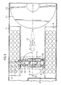
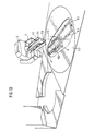
- the armored howitzer shown in overall view in FIGS. 1 and 2 consists of a tracked vehicle 1 on which a turret 2 is rotatably arranged, which carries a heavy weapon 3.
- the tower 2 is arranged in the area behind the center of the vehicle.
- a driver's seat 1.3 is located in the front part of the vehicle 1. As explained in more detail below, the storeys are stored in the area of the center of the vehicle and the vehicle can be entered and exited in a manner not specifically shown through a large door arranged in the rear.
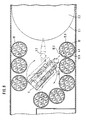
- the projectile supply takes place, as can be seen in FIG. 2 in an overview, such that, as will be described in more detail below, the projectiles are removed from a projectile magazine arranged in the center of the vehicle by means of the projectile transporter 5. They are then transferred from the projectile transporter 5 to the transport rail 6 arranged below the turret 2, from which they are taken over by means of a projectile transfer arm pivotable about the shield pin 2.4 of the weapon 3 and brought into the loading position behind the weapon 3.
- a storey transporter 5 Arranged between the storey magazines 4 is a storey transporter 5 which has a base frame 5.5 which is arranged directly above the vehicle floor and which can be rotated about an axis 5.4 which is perpendicular to the vehicle floor 1.1 on the vehicle longitudinal center axis 1.4.
- a transport arm 5.1 On the base frame 5.5, a transport arm 5.1 is guided so as to be displaceable in its longitudinal direction parallel to the vehicle floor 1.1 via rails 5.6 arranged thereon, and a gripping device 5.2 is pivotably arranged on the free outer end of the transport arm 5.1.
- the storeys 4.1 are each arranged in the storey magazine 4 to form a plurality of rows 10 standing one behind the other and radiating outwards, which intersect in the axis of rotation 5.4 of the base frame 5.5.
- the mode of operation of the projectile transporter 5 is accordingly as follows:
- the base frame 5.5 pivots into an angular position so that it is aligned with one of the lines 10.
- the transport arm 5.1 is extended and the gripping device 5.2 (see FIG. 3) grasps the projectile 4.1, the projectile clamp is opened and the projectile is pulled up out of its position.
- the base frame 5.5 is then pivoted in the vehicle longitudinal direction 1.4 and the projectile is finally brought into the transfer position 1.2, which is located between the projectile transporter 5 and the rotation area 2.1 of the tower platform 2.2.
- storey magazines are arranged in the middle of the vehicle on both sides of the storey transporter, which are designed as block stores 11 in which the stationary storeys are arranged along the inner walls parallel to the longitudinal axis 1.4 of the vehicle.
- the storeys 4.1 are also held in the block magazines 11 by means of known clamping devices (not shown).
- the projectile transporter 5 has a further degree of freedom in that it can be moved in the longitudinal direction 1.4 of the vehicle.
- a longitudinal slide 5.7 is guided on two rails 5.8 fastened to the vehicle floor 1.1 parallel to the longitudinal axis 1.4 of the vehicle, on which the base frame 5.5 already described is rotatably mounted about the axis 5.4.
- the transport arm 5.1 which can be displaced on the rails 5.6 of the base arm, with the gripping device 5.2 is arranged on the base frame at the outer end.
- the projectile transporter 5 is in the vehicle longitudinal direction 1.4 up to the desired position in front of one of the two Bullet magazines 11 driven. Then the base frame 5.5 is pivoted into a position perpendicular to the longitudinal axis 1.4 of the vehicle, the transport arm 5.1 extends and the gripping device 5.2 grips a projectile 4.1 and pulls it out of its position. The base frame 5 is again pivoted in the vehicle longitudinal direction 1.4 and the projectile transporter 5 is displaced in the longitudinal direction until the projectile is in the transfer position 1.2.
- the standing projectiles 4.1 are mounted in a plurality of drum magazines 12 arranged along the inner walls of the vehicle around the projectile transporter 5 and each rotatable about a vertical axis 12.1.
- the cylindrical outer walls 12.3 of the drum magazines are firmly connected to the vehicle floor 1.1 and each have a projectile removal opening 12.2 which is aligned with the axis of rotation 5.4 of the base frame 5.5 of the projectile transporter 5.
- the projectiles stand on a base plate 12.4 arranged in the housing of the drum magazine and are fixed in a star-shaped projectile holder 12.5.
- the base plate 12.4 can be moved in cycles by means of an electric drive motor 12.6, so that each floor of the drum magazine can optionally be removed from the floor transporter 5 through the floor removal opening 12.2.
- the projectile transporter 5 in this embodiment is designed in the same way as in the embodiment according to FIGS. 3 and 4, ie it can only be rotated about the axis of rotation 5.4 perpendicular to the vehicle floor 1.1.
- the base frame 5.5 is pivoted in a direction which is aligned with the removal opening of the activated drum magazine 12, the transport arm 5.1 is extended and the bullet 4.1 is removed from the bullet holder 12.5 by means of the gripping device 5.2 and finally brought into the transfer position 1.2.
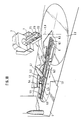
- a rotatably mounted transport rail 6 is arranged centrally under the rotatable tower 2 on the vehicle floor 1.1. It essentially consists of a turntable 6.3, which is rotatable about the axis of rotation 2.3 of the tower 2, is mounted parallel to the vehicle floor 1.1, and has telescopic rails 6.1 fastened thereon. The telescopic rails 6.1 can be extended radially to the turntable 6.3.
- a standby shell 6.2 which can be pivoted by approximately 90 ° to the rotational plane is arranged on the telescopic rails 6.1. The horizontal axis of rotation of the standby shell 6.2 is arranged on its side facing away from the axis of rotation 2.3 of the turntable 6.3.
- a projectile transfer arm 7 is also pivotably mounted, which can be lowered into the vehicle independently of the weapon in a plane in or parallel to the elevation plane and is designed such that its individual parts are located below and behind the weapon end.
- a charging cradle 7.3 is arranged, which is firmly connected to the projectile transfer arm 7.
- the overall arrangement is such that the charging cradle 7.3 in the raised position of the projectile transfer arm 7 is aligned with the barrel axis of the weapon 3, while in the completely lowered position of the projectile transfer arm 7 it is perpendicular to the vehicle floor 1.1 in the range of motion of the transport rail 6.
- a projectile clamping device 7.1 and an attachment device 7.2 are also arranged in a manner known per se.
- the projectile transport proceeds from the transfer point 1.2 through the projectile transporter 5 to the loading position in the following steps:
- the projectile transporter 5 is in the transfer position which can be seen particularly clearly from FIG. 4.
- the transport rail 6 first pivots into the takeover position shown in FIG. 3.
- the telescopic rails 6.1 with the swiveling stand-by shell 6.2 slide, as shown in FIG. 10, under the floor 4.1 brought into the transfer position.
- the gripping device 5.2 of the projectile transporter 5 tilts the projectile into a horizontal position and places it in the ready shell 6.2.
- the telescopic rails 6.1 with the standby shell 6.2 move back into the rotation region 2.1 of the transport rail 6, as shown in FIG. 11.
- the projectile transporter 5 can be brought back into a position in which it can remove a new projectile from the magazine.
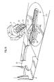
- the transport rail 6 swivels the projectile lying in the standby shell 6.2 under the tower platform 2.2 into the azimuth position of the weapon, which is shown in FIG. 12.
- Fig. 12 can also be seen that the projectile transfer arm 7 of the weapon 3 is pivoted down into the vehicle interior so that the charging cradle 7.3 is perpendicular to the turntable at the end of the transport rail 6.
- the ready shell 6.2 swings the projectile 4.1 from its horizontal into a vertical position directly into the charging shell 7.3 of the projectile transfer arm 7 and swings back empty into its initial position.
- the projectile 4.7 is fixed in the charging cradle 7.3 by means of the projectile clamping device 7.1 and the projectile transfer arm 7 swivels with the projectile arranged in the charging cradle 7.3 into the elevation position of the weapon 3 and locks there automatically with the weapon system. This position is shown in more detail in Fig. 13.
- the attachment device 7.2 which is not described in more detail here, then conveys the projectile 4.1 into the loading space of the weapon 3.
- the transport rail 6 can already be pivoted back into the initial position in the longitudinal direction of the vehicle to take over a further floor.
- the drive devices for actuating the projectile transporter 5, the transport rail 6 and the projectile transfer arm 7 are designed in a manner known per se and are not specifically illustrated and described.
- the entire feed path of the storeys can be done automatically, controlled by appropriate electronic Control devices. If partial functions fail, the individual parts of the projectile feeding device can also be operated manually.
- a projectile can be removed manually from the projectile magazines 4, 11 and 12 and inserted into the standby shell 6.2.
- a seat shell 5.3 is fastened to the base frame 5.5 of the projectile transporter 5, as can be seen particularly well in FIGS. 4, 6, 7 and 9. All drives of the movement axes are electrically and mechanically decoupled. A crew member 9 can now perform all movements of the projectile transporter 5 with little physical strength in a seated position.
- the mechanical devices necessary for this, such as handles, Bowden cables and the like, are not shown separately.
- the projectile in a position tilted by approximately 45 ° is passed directly by the crew member 9 sitting on the projectile transporter into the combat area, where it is taken over by a loading gunner.
- the projectile delivery device described can also be used in a simple manner for loading and unloading the vehicle with ammunition.
- a feed opening 8 (see FIG. 2) is provided behind the area of the transport rail 6 in the rear area of the vehicle, through which the extended ready tray 6.2 can be loaded from the outside.
- the projectiles are placed manually in the standby shell 6.2 and automatically conveyed further by the transport rail 6, after which they are either lifted directly to the weapon 3 by means of the projectile transfer arm 7 or, when the projectile transfer arm is pivoted up, by the gripping device 5.2 of the projectile transporter 5 from the folded up position Ready shell 6.2 taken over and fed to the storey magazine. Unloading takes place in the opposite direction and the grenades can be removed from the rear of the vehicle.
Description
Die Erfindung betrifft ein Kampffahrzeug, insbesondere eine Panzerhaubitze, gemäß den Merkmalen aus dem Oberbegriff des Patentanspruchs 1.The invention relates to a combat vehicle, in particular a self-propelled howitzer, according to the features from the preamble of patent claim 1.
Ein derartiges Kampffahrzeug ist beispielsweise in der älteren, nicht vorveröffentlichten Patentanmeldung gemäß DE-A-3642920 beschrieben, die lediglich ein älteres nationales Recht darstellt.Such a combat vehicle is described for example in the older, not prepublished patent application according to DE-A-3642920, which only represents an older national law.
Bei dem älteren Kampffahrzeug werden die Geschosse vom Geschoßtransporter mittels eines Transportarmes erfaßt, der senkrecht zum Fahrzeugboden angeordnet ist und in einer Ebene parallel zum Fahrzeugboden bewegbar ist. Am unteren Ende des Transportarms ist eine schwenkbare Greifvorrichtung angeordnet. Der Transportarm ist an einer in Fahrzeuglängsrichtung ausgerichteten Schiene verschiebbar aufgehängt, die ihrerseits an zwei in Querrichtung angeordneten Schienen hängt und in Querrichtung verschiebbar ist.In the older combat vehicle, the projectiles are gripped by the projectile transporter by means of a transport arm which is arranged perpendicular to the vehicle floor and can be moved in one plane parallel to the vehicle floor. A swiveling gripping device is arranged at the lower end of the transport arm. The transport arm is slidably suspended on a rail aligned in the vehicle longitudinal direction, which in turn hangs on two rails arranged in the transverse direction and is displaceable in the transverse direction.
Bei der Geschoßzuführung wird das vom Transportarm erfaßte Geschoß zunächst um 90° gedreht und in Fahrzeuglängsrichtung ausgerichtet. Es wird schließlich in eine in Fahrzeuglängsrichtung angeordnete, fest mit dem Fahrzeugboden verbundene Bereitschaftsschale eingelegt, aus der es mittels eines Ausstoßers in eine Transportschiene eingeschoben und in dieser durch Fördermittel weiter nach hinten transportiert wird. Die Transportschiene wird in Azimut auf die momentane Stellung der Waffe ausgerichtet. Dann wird der Geschoßübergabearm, an dem eine schwenkbare Ladeschale angeordnet ist, abgesenkt, und zwar so, daß die Ladeschale in die Transportschiene eingeführt ist und koaxial zu ihr steht. Das Geschoß kann nunmehr in die Ladeschale eingeschoben werden und nach dem Hochschwenken des Geschoßübergabearms in die Endposition hinter dem Waffenende gebracht werden.When the bullet is fed, the bullet gripped by the transport arm is first rotated by 90 ° and aligned in the longitudinal direction of the vehicle. Finally, it is placed in a standby shell, which is arranged in the longitudinal direction of the vehicle and is firmly connected to the vehicle floor, from which it is inserted into a transport rail by means of an ejector and transported further backwards by means of conveying means. The transport rail is aligned in azimuth to the current position of the weapon. Then the projectile transfer arm, on which a swiveling charging cradle is arranged, is lowered in such a way that the charging cradle is inserted into the transport rail and is coaxial with it. The projectile can now be inserted into the charging cradle and, after the projectile transfer arm has been swung up, can be brought into the end position behind the weapon end.
Der Erfindung liegt die Aufgabe zugrunde, ein Kampffahrzeug der eingangs und im Oberbegriff des Patentanspruchs 1 ausgebildeten Bauart derart auszugestalten, daß für den automatischen Transport der Geschosse möglichst wenig Bewegungsachsen benötigt werden, daß mit geringstem Aufwand Vorrichtungen angeordnet werden können, die bei Energieausfall oder anderen Störungen einen manuellen Geschoßtransport ohne große körperliche Kraftaufwendung möglich machen und daß ein Fluchtweg für den im vorderen Teil des Fahrzeugs sitzenden Fahrer zum Ausgang im Heck des Fahrzeugs erhalten bleibt, der möglichst wenig durch die Einrichtungen der Geschoßzuführungsvorrichtung räumlich versperrt ist.The invention has for its object to design a combat vehicle of the type initially formed and in the preamble of claim 1 in such a way that as few axes of movement are required for the automatic transport of the projectiles that devices can be arranged with the least effort in the event of energy failure or other disturbances make a manual projectile transport possible without great physical exertion and that an escape route for the driver sitting in the front part of the vehicle to the exit in the rear of the vehicle is retained, which is as little as possible spatially blocked by the facilities of the projectile delivery device.
Die Lösung dieser Aufgabe erfolgt erfindungsgemäß mit den Merkmalen aus dem kennzeichnenden Teil des Patentanspruchs 1.This object is achieved according to the invention with the features from the characterizing part of patent claim 1.
Vorteilhafte Ausführungsformen des erfindungsgemäßen Kampffahrzeuges sind in den Ansprüchen 2 bis 8 beschrieben.Advantageous embodiments of the combat vehicle according to the invention are described in claims 2 to 8.
Der der Erfindung zugrunde liegende Gedanke bestand in Weiterbildung des in der älteren Anmeldung beschriebenen Lösungsansatzes darin, die Anordnung der Geschosse in der Fahrzeugmitte sowie die Ausbildung des Geschoßtransporters so zu wählen, daß der Geschoßtransporter in einer sehr niedrigen Bauweise ausgeführt werden kann und zum Geschoßtransport nur wenig Bewegungsachsen benötigt. Die flache Bauweise ermöglicht es weiterhin, daß der Fluchtweg durch den Innenraum des Fahrzeugs nur wenig behindert ist und auf dem Geschoßtransporter ein Sitz für eine Bedienungsperson bei manueller Bedienung angeordnet werden kann. Auch der Weitertransport der Geschosse vom Geschoßtransporter bis in die Ladeposition ist vereinfacht, indem die Bereitschaftsschale selbst verschiebbar und verschwenkbar ausgebildet ist, so daß das Geschoß direkt aus der Bereitschaftsschale in die Ladeschale ohne zusätzliche Fördermittel überführt werden kann.The idea on which the invention is based consisted in further development of that described in the earlier application Solution approach in choosing the arrangement of the projectiles in the middle of the vehicle and the design of the projectile transporter so that the projectile transporter can be designed in a very low design and requires only a few axes of movement for projectile transport. The flat design also makes it possible that the escape route is only slightly obstructed by the interior of the vehicle and a seat for an operator with manual operation can be arranged on the floor transporter. The further transport of the projectiles from the projectile transporter to the loading position is simplified in that the standby shell itself is designed to be displaceable and pivotable, so that the projectile can be transferred directly from the standby shell to the loading shell without additional funding.
Der gesamte Geschoßtransport aus dem Geschoßmagazin bis in die Ladeposition kann automatisch erfolgen, gesteuert von an sich bekannten elektronischen Steuereinrichtungen. Hierbei sind beispielsweise die Lagekoordinaten der Geschosse im Geschoßmagazin und weitere Geschoßdaten in einer Munitionsfluß-Logik abgespeichert, so daß bereits bei Betätigung des Geschoßtransporters die Positionen vorgegebener Geschosse angewählt werden können.The entire projectile transport from the projectile magazine to the loading position can be carried out automatically, controlled by electronic control devices known per se. Here, for example, the position coordinates of the storeys in the storey magazine and further storey data are stored in ammunition flow logic so that the positions of predetermined storeys can be selected as soon as the storey transporter is actuated.
Der Aufbau der gesamten Geschoßzuführungsvorrichtung aus mehreren Einzeleinrichtungen macht es auch möglich, beim Ausfall von Teilfunktionen diese durch manuelle Eingriffe zu ersetzen. So kann beispielsweise beim Ausfall des Geschoßtransporters ein Geschoß manuell aus den Geschoßmagazinen entnommen und in die Bereitschaftsschale eingelegt werden. Dies wird weiter unten anhand eines Ausführungsbeispiels näher erläutert.The construction of the entire projectile delivery device from several individual devices also makes it possible to replace them with manual interventions if partial functions fail. If, for example, the projectile transporter fails, a projectile can be manually removed from the storey magazines and inserted into the standby shell. This is explained in more detail below using an exemplary embodiment.
Ebenso kann beim Ausfall der Transportschiene das Geschoß vom Geschoßtransporter manuell abgenommen und in die Ladeposition gebracht werden.Likewise, if the transport rail fails, the projectile can be manually removed from the projectile transporter and brought into the loading position.
Mit dem erfindungsgemäßen Kampffahrzeug werden weiterhin u.a. folgende Vorteile erreicht:
- 1.
- Beim Beladen des Fahrzeugs tritt nur eine sehr geringe Schwerpunktsverlagerung auf;
- 2.
- es kann ein großer Munitionsvorrat aufgenommen werden, wobei ein leistungsfähiger Munitionsfluß erhalten bleibt;
- 3.
- es bleibt im Inneren ein freier Kampfraum mit durchgehendem Boden erhalten und insbesondere ein freier Fluchtweg nach hinten, wobei das Fahrzeug durch eine große Hecktür betreten und verlassen werden kann;
- 4.
- das Zuführen der Geschosse in die Ladeposition ist automatisch und von Hand mittels einfacher Baugruppen möglich, die außerdem zum Aufmunitionieren des Fahrzeugs verwendbar sind, wobei die stehende Lagerung der Geschosse eine besonders einfache Halterung der Geschosse im Magazin und eine einfache Entnahme und Handhabung der Geschosse im manuellen Betrieb ermöglicht.
The following advantages, among others, are achieved with the combat vehicle according to the invention:
- 1.
- When loading the vehicle there is only a very slight shift in the center of gravity;
- 2nd
- a large supply of ammunition can be taken up while maintaining an efficient flow of ammunition;
- 3rd
- inside there is a free combat area with a continuous floor and in particular a free escape route to the rear, whereby the vehicle can be entered and exited through a large rear door;
- 4th
- the projectiles can be fed into the loading position automatically and manually by means of simple assemblies, which can also be used for ammunitioning the vehicle, the vertical storage of the projectiles being a particularly simple way of holding the projectiles in the magazine and of simply removing and handling the projectiles in manual fashion Operation enables.
Im folgenden werden anhand der beigefügten Zeichnungen Ausführungsbeispiele für ein Kampffahrzeug nach der Erfindung und der Ablauf der Zuführung der Geschosse aus dem Geschoßmagazin in die Ladeposition näher erläutert.In the following, exemplary embodiments of a combat vehicle according to the invention and the process of feeding the projectiles from the projectile magazine into the loading position are explained in more detail with reference to the accompanying drawings.
In den Zeichnungen zeigen:
- Fig. 1
- eine Gesamtansicht einer Panzerhaubitze in perspektivischer Darstellung;
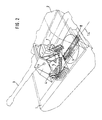
- Fig. 2
- in einer perspektivischen, stark schematisierten Darstellung die Ausgestaltung des Fahrzeuginnenraums einer Panzerhaubitze nach Fig. 1 mit einzelnen Einrichtungen der Geschoßzuführungsvorrichtung;
- Fig. 3
- in vergrößerter perspektivischer Darstellung einen Teil des Fahrzeuginnenraums bei einer ersten Ausführungsform der Erfindung;
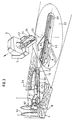
- Fig. 4
- in einer Teildarstellung der Fig. 3 den Fahrzeuginnenraum in einer anderen Phase des Geschoßtransportes;
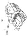
- Fig. 5
- in einer vergrößerten Darstellung eine Aufsicht auf einen Teil des Fahrzeuginneren bei einer zweiten Ausführungsform der Erfindung;
- Fig. 6
- in einer Ansicht in Fahrzeuglängsrichtung den Teil des Innenraums des Fahrzeugs gemäß Fig. 5;
- Fig. 7
- in einer Ansicht quer zur Fahrzeuglängsrichtung den Teil des Innenraums des Fahrzeugs nach Fig. 5 und 6 in einer anderen Phase des Geschoßtransportes;
- Fig. 8
- in einer Aufsicht auf einen Teil des Fahrzeuginneren eine dritte Ausführungsform der Erfindung;
- Fig. 9
- in einer Ansicht in Fahrzeuglängsrichtung den Teil des Fahrzeuginneren gemäß Fig. 8;
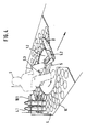
- Fig. 10
- eine Ansicht des Fahrzeuginneren analog Fig. 3 in einer anderen Phase des Geschoßtransportes;
- Fig. 11 bis 13
- in Darstellungen analog Fig. 10 weitere Phasen des Geschoßtransportes.
The drawings show:
- Fig. 1
- an overall view of a self-propelled howitzer in a perspective view;
- Fig. 2
- in a perspective, highly schematic representation of the configuration of the vehicle interior of a self-propelled howitzer according to FIG. 1 with individual devices of the projectile feeding device;
- Fig. 3
- an enlarged perspective view of part of the vehicle interior in a first embodiment of the invention;
- Fig. 4
- 3 the vehicle interior in another phase of the projectile transport;
- Fig. 5
- an enlarged view of a part of the vehicle interior in a second embodiment of the invention;
- Fig. 6
- in a view in the vehicle longitudinal direction, the part of the interior of the vehicle according to FIG. 5;
- Fig. 7
- in a view transverse to the vehicle longitudinal direction, the part of the interior of the vehicle according to Figures 5 and 6 in another phase of the projectile transport;
- Fig. 8
- in a plan view of a part of the vehicle interior, a third embodiment of the invention;
- Fig. 9
- in a view in the vehicle longitudinal direction the part of the vehicle interior according to FIG. 8;
- Fig. 10
- a view of the vehicle interior analogous to Figure 3 in another phase of the projectile transport;
- 11 to 13
- in representations analogous to FIG. 10 further phases of the projectile transport.
Die in den Fig. 1 und 2 in Gesamtdarstellung gezeigte Panzerhaubitze besteht aus einem Kettenfahrzeug 1, auf dem ein Turm 2 drehbar angeordnet ist, welcher eine schwere Waffe 3 trägt.The armored howitzer shown in overall view in FIGS. 1 and 2 consists of a tracked vehicle 1 on which a turret 2 is rotatably arranged, which carries a
Wie ersichtlich ist der Turm 2 im Bereich hinter der Fahrzeugmitte angeordnet.As can be seen, the tower 2 is arranged in the area behind the center of the vehicle.
Im Vorderteil des Fahrzeugs 1 befindet sich ein Fahrerplatz 1.3. Wie weiter unten näher erläutert, sind im Bereich der Fahrzeugmitte die Geschosse gelagert und das Fahrzeug kann in nicht eigens dargestellter Weise durch eine im Heck angeordnete große Tür betreten und verlassen werden.A driver's seat 1.3 is located in the front part of the vehicle 1. As explained in more detail below, the storeys are stored in the area of the center of the vehicle and the vehicle can be entered and exited in a manner not specifically shown through a large door arranged in the rear.
Durch die Lagerung der Munition im Bereich der Fahrzeugmitte wird erreicht, daß der Schwerpunkt des Fahrzeugs sich beim Beladen nur geringfügig verlagert.Storage of the ammunition in the area of the center of the vehicle means that the center of gravity of the vehicle is only slightly shifted during loading.
Im folgenden werden nur die für den Geschoßtransport wesentlichen Teile des Fahrzeugs näher erläutert, während andere, an sich bekannte Einrichtungsteile, die z.T. in den Zeichnungen mit dargestellt sind, nicht näher erläutert werden.In the following, only the parts of the vehicle that are essential for the projectile transport will be explained in more detail, while other, known parts of the device, some of which are also shown in the drawings, are not explained in detail.
Die Geschoßzuführung erfolgt, wie Fig. 2 in Übersicht zu entnehmen, dergestalt, daß, wie weiter unten im einzelnen näher beschrieben wird, die Geschosse aus einem in Fahrzeugmitte angeordneten Geschoßmagazin mittels des Geschoßtransporters 5 entnommen werden. Sie werden dann vom Geschoßtransporter 5 auf die unterhalb des Turms 2 angeordnete Transportschiene 6 übergeben, von der sie mittels eines um den Schildzapfen 2.4 der Waffe 3 schwenkbaren Geschoßübergabearmes übernommen und in die Ladeposition hinter der Waffe 3 gebracht werden.The projectile supply takes place, as can be seen in FIG. 2 in an overview, such that, as will be described in more detail below, the projectiles are removed from a projectile magazine arranged in the center of the vehicle by means of the
Im folgenden werden drei Ausführungsformen der gesamten Geschoßzuführungsvorrichtung beschrieben, die sich im wesentlichen durch die Ausbildung und Anordnung der Geschoßmagazine und die Ausbildung und Anordnung des Geschoßtransporters unterscheiden, während die Ausbildung der Transportschiene 6 und des Geschoßübergabearms 7 bei allen Ausführungsformen die gleiche ist.In the following three embodiments of the entire projectile delivery device are described, which are essentially the design and arrangement of the Projectile magazines and the design and arrangement of the projectile transporter differ, while the design of the
Bei einer ersten Ausführungsform, die in den Fig. 3 und 4 dargestellt ist, sind zu beiden Seiten des Geschoßtransporters 5 Geschoßmagazine 4 angeordnet, in denen die Geschosse 4.1 stehend gelagert sind, wobei sie durch an sich bekannte und nicht näher erläuterte Halterungen 10.1 in dieser Lage festgehalten werden.In a first embodiment, which is shown in FIGS. 3 and 4, 5
Zwischen den Geschoßmagazinen 4 ist ein Geschoßtransporter 5 angeordnet, der einen unmittelbar über dem Fahrzeugboden angeordneten Grundrahmen 5.5 aufweist, der um eine Achse 5.4, die senkrecht zum Fahrzeugboden 1.1 auf der Fahrzeuglängsmittelachse 1.4 steht, drehbar ist. Auf dem Grundrahmen 5.5 ist ein Transportarm 5.1 über an ihm angeordnete Schienen 5.6 in seiner Längsrichtung parallel zum Fahrzeugboden 1.1 verschiebbar geführt und am freien äußeren Ende des Transportarms 5.1 ist eine Greifvorrichtung 5.2 schwenkbar angeordnet.Arranged between the
Die Geschosse 4.1 sind im Geschoßmagazin 4 jeweils zu mehreren hintereinander stehend auf strahlenförmig nach außen weisenden Linien 10 angeordnet, die sich in der Drehachse 5.4 des Grundrahmens 5.5 schneiden.The storeys 4.1 are each arranged in the
Die Funktionsweise des Geschoßtransporters 5 ist demnach wie folgt:The mode of operation of the
Zur Entnahme eines Geschosses schwenkt der Grundrahmen 5.5 in eine Winkelposition, daß er fluchtend zu einer der Linien 10 steht. Der Transportarm 5.1 wird ausgefahren und die Greifvorrichtung 5.2 (s. Fig. 3) erfaßt das Geschoß 4.1, die Geschoßklemmung wird geöffnet und das Geschoß wird stehend aus seiner Position herausgezogen. Der Grundrahmen 5.5 wird dann in die Fahrzeuglängsrichtung 1.4 eingeschwenkt und das Geschoß schließlich in die Übergabeposition 1.2 gebracht, die sich zwischen dem Geschoßtransporter 5 und dem Rotationsbereich 2.1 der Turmbühne 2.2 befindet.To remove a projectile, the base frame 5.5 pivots into an angular position so that it is aligned with one of the
Der weitere Transport des Geschosses wird weiter unten näher erläutert.The further transport of the projectile is explained in more detail below.
Bei der Ausführungsform nach den Fig. 5 bis 7 sind in Fahrzeugmitte zu beiden Seiten des Geschoßtransporters 5 Geschoßmagazine angeordnet, die als Blockmagazine 11 ausgebildet sind, in denen die stehenden Geschosse entlang der Innenwände parallel zur Längsachse 1.4 des Fahrzeuges angeordnet sind. Auch in den Blockmagazinen 11 sind die Geschosse 4.1 durch nicht näher dargestellte an sich bekannte Klemmvorrichtungen festgehalten.In the embodiment according to FIGS. 5 to 7, 5 storey magazines are arranged in the middle of the vehicle on both sides of the storey transporter, which are designed as
Bei dieser Ausführungsform besitzt der Geschoßtransporter 5 einen weiteren Freiheitsgrad, indem er in Fahrzeuglängsrichtung 1.4 verfahrbar ist. Zu diesem Zweck ist auf zwei parallel zur Längsachse 1.4 des Fahrzeuges am Fahrzeugboden 1.1 befestigten Schienen 5.8 ein Längsschlitten 5.7 geführt, auf dem der bereits beschriebene Grundrahmen 5.5 um die Achse 5.4 drehbar gelagert ist. Auf dem Grundrahmen ist wiederum der auf den Schienen 5.6 des Grundarms verschiebbare Transportarm 5.1 mit der Greifvorrichtung 5.2 am äußeren Ende angeordnet.In this embodiment, the
Zur Entnahme der Geschosse wird, wie aus Fig. 5 ersichtlich, der Geschoßtransporter 5 in Fahrzeuglängsrichtung 1.4 bis in die gewünschte Position vor einem der beiden Geschoßmagazine 11 gefahren. Dann wird der Grundrahmen 5.5 in eine Stellung senkrecht zur Fahrzeuglängsachse 1.4 geschwenkt, der Transportarm 5.1 fährt aus und die Greifvorrichtung 5.2 ergreift ein Geschoß 4.1 und zieht es aus seiner Position. Der Grundrahmen 5 wird wieder in die Fahrzeuglängsrichtung 1.4 eingeschwenkt und der Geschoßtransporter 5 in Längsrichtung verschoben bis sich das Geschoß in der Übergabeposition 1.2 befindet.For the removal of the projectiles, as can be seen from FIG. 5, the
Bei der Ausführungsform nach den Fig. 8 und 9 sind die stehenden Geschosse 4.1 in mehreren, entlang der Innenwände des Fahrzeugs um den Geschoßtransporter 5 herum angeordneten, jeweils um eine senkrechte Achse 12.1 drehbaren Trommelmagazinen 12 gelagert. Die zylindrischen Außenwände 12.3 der Trommelmagazine sind fest mit dem Fahrzeugboden 1.1 verbunden und weisen jeweils eine Geschoßentnahmeöffnung 12.2 auf, die auf die Drehachse 5.4 des Grundrahmens 5.5 des Geschoßtransporters 5 ausgerichtet ist. Die Geschosse stehen auf einer im Gehäuse des Trommelmagazins angeordneten Grundplatte 12.4 und sind in einer sternförmig ausgebildeten Geschoßhalterung 12.5 fixiert. Die Grundplatte 12.4 ist mittels eines elektrischen Antriebsmotors 12.6 taktweise bewegbar, so daß jedes Geschoß des Trommelmagazins wahlweise vom Geschoßtransporter 5 durch die Geschoßentnahmeöffnung 12.2 entnommen werden kann.In the embodiment according to FIGS. 8 and 9, the standing projectiles 4.1 are mounted in a plurality of
Der Geschoßtransporter 5 ist bei dieser Ausführungsform in der gleichen Weise ausgebildet wie bei der Ausführungsform nach den Fig. 3 und 4, d.h. er ist lediglich um die senkrecht zum Fahrzeugboden 1.1 stehende Drehachse 5.4 drehbar.The
Bei der Geschoßentnahme wird der Grundrahmen 5.5 in eine Richtung geschwenkt, die mit der Entnahmeöffnung des angesteuerten Trommelmagazins 12 fluchtet, der Transportarm 5.1 wird ausgefahren und mittels der Greifvorrichtung 5.2 wird das Geschoß 4.1 aus der Geschoßhalterung 12.5 entnommen und schließlich in die Übergabeposition 1.2 gebracht.When the bullet is removed, the base frame 5.5 is pivoted in a direction which is aligned with the removal opening of the activated
Im folgenden wird der Weitertransport der Geschosse von der Übergabeposition 1.2 des Geschoßtransporters 5 an beschrieben.The further transport of the projectiles from transfer position 1.2 of the
Zentrisch unter dem drehbaren Turm 2 ist auf dem Fahrzeugboden 1.1 eine drehbar gelagerte Transportschiene 6 angeordnet. Sie besteht im wesentlichen aus einem um die Drehachse 2.3 des Turmes 2 drehbaren, parallel zum Fahrzeugboden 1.1 gelagerten Drehteller 6.3 und auf ihm befestigten Teleskopschienen 6.1. Die Teleskopschienen 6.1 sind radial zum Drehteller 6.3 ausfahrbar. An den Teleskopschienen 6.1 ist eine um ca. 90° zur Drehebene schwenkbare Bereitschaftsschale 6.2 angeordnet. Dabei ist die horizontale Drehachse der Bereitschaftsschale 6.2 an ihrem von der Drehachse 2.3 des Drehtellers 6.3 abgewandten Seite angeordnet.A rotatably mounted
An den Schildzapfenlagern 2.4 der Waffe 3 ist weiterhin ein Geschoßübergabearm 7 schwenkbar gelagert, der unabhängig von der Waffe in einer Ebene in oder parallel zur Elevationsebene in das Fahrzeug hinein absenkbar ist und so gestaltet ist, daß seine Einzelteile jeweils unterhalb und hinter dem Waffenende liegen. Am hinteren Ende des Geschoßübergabearms 7 ist eine Ladeschale 7.3 angeordnet, die fest mit dem Geschoßübergabearm 7 verbunden ist. Die Gesamtanordnung ist so, daß die Ladeschale 7.3 in der angehobenen Stellung des Geschoßübergabearms 7 fluchtend zur Rohrseelenachse der Waffe 3 angeordnet ist, während sie in der völlig abgesenkten Stellung des Geschoßübergabearmes 7 senkrecht zum Fahrzeugboden 1.1 im Bewegungsbereich der Transportschiene 6 steht. An der Ladeschale 7.3 sind weiterhin in an sich bekannter Ausführung eine Geschoßklemmvorrichtung 7.1 sowie eine Ansetzvorrichtung 7.2 angeordnet.On the shield journal bearings 2.4 of the
Der Geschoßtransport geht, wie anhand der Fig. 10 bis 13 ersichtlich, vom Übergabepunkt 1.2 durch den Geschoßtransporter 5 bis zur Ladeposition in folgenden Schritten vor sich:The projectile transport, as can be seen from FIGS. 10 to 13, proceeds from the transfer point 1.2 through the
Der Geschoßtransporter 5 steht in der aus Fig. 4 besonders deutlich ersichtlichen Übergabeposition. Die Transportschiene 6 schwenkt zunächst in die Fig. 3 zu entnehmende Übernahmeposition. Die Teleskopschienen 6.1 mit der schwenkbaren Bereitschaftsschale 6.2 schieben sich, wie in Fig. 10 dargestellt, unter das in die Übergabeposition gebrachte Geschoß 4.1. Die Greifvorrichtung 5.2 des Geschoßtransporters 5 kippt das Geschoß in eine horizontale Lage und legt es in die Bereitschaftsschale 6.2. Die Teleskopschienen 6.1 mit der Bereitschaftsschale 6.2 fahren zurück in den Rotationsbereich 2.1 der Transportschiene 6, wie dies in Fig. 11 dargestellt ist.The
In den Fig. 11 bis 13 ist aus Gründen der Vereinfachung der Geschoßtransporter 5 nicht dargestellt.11 to 13 is not shown for reasons of simplification of the
Während der Bewegung der Transportschiene 6 kann der Geschoßtransporter 5 wieder in eine Position gebracht werden, in der er ein neues Geschoß aus dem Magazin entnehmen kann.During the movement of the
Die Transportschiene 6 schwenkt das in der Bereitschaftsschale 6.2 liegende Geschoß unter der Turmbühne 2.2 in die Azimutposition der Waffe, die in Fig. 12 dargestellt ist. Ebenfalls Fig. 12 ist zu entnehmen, daß der Geschoßübergabearm 7 der Waffe 3 so in das Fahrzeuginnere herabgeschwenkt ist, daß die Ladeschale 7.3 senkrecht zum Drehteller am Ende der Transportschiene 6 steht. Die Bereitschaftsschale 6.2 schwenkt das Geschoß 4.1 aus seiner Horizontalen in eine vertikale Position direkt in die Ladeschale 7.3 des Geschoßübergabearms 7 hinein und schwenkt sofort leer in ihre Ausgangslage zurück.The
Das Geschoß 4.7 ist in der Ladeschale 7.3 mittels der Geschoßklemmvorrichtung 7.1 fixiert und der Geschoßübergabearm 7 schwenkt mit dem in der Ladeschale 7.3 angeordneten Geschoß in die Elevationslage der Waffe 3 und verriegelt sich dort automatisch mit der Waffenanlage. Diese Stellung ist in Fig. 13 genauer dargestellt. Die hier nicht näher beschriebene Ansetzvorrichtung 7.2 befördert dann das Geschoß 4.1 in den Ladungsraum der Waffe 3.The projectile 4.7 is fixed in the charging cradle 7.3 by means of the projectile clamping device 7.1 and the
Währenddessen kann die Transportschiene 6 bereits wieder in die Ausgangslage in Fahrzeuglängsrichtung zurückgeschwenkt werden zur Übernahme eines weiteren Geschosses.In the meantime, the
Die Antriebsvorrichtungen zur Betätigung des Geschoßtransporters 5, der Transportschiene 6 sowie des Geschoßübergabearmes 7 sind in an sich bekannter Weise ausgebildet und nicht eigens dargestellt und beschrieben.The drive devices for actuating the
Der gesamte Zuführungsgang der Geschosse kann automatisch erfolgen, gesteuert von entsprechenden elektronischen Steuereinrichtungen. Beim Ausfall von Teilfunktionen können aber die einzelnen Teile der Geschoßzuführungsvorrichtung auch manuell betrieben werden.The entire feed path of the storeys can be done automatically, controlled by appropriate electronic Control devices. If partial functions fail, the individual parts of the projectile feeding device can also be operated manually.
So kann beispielsweise beim Ausfall des Geschoßtransporters 5 ein Geschoß manuell aus den Geschoßmagazinen 4, 11 und 12 entnommen und in die Bereitschaftsschale 6.2 eingelegt werden.For example, if the
Hierzu wird auf dem Grundrahmen 5.5 des Geschoßtransporters 5 eine Sitzschale 5.3 befestigt, wie dies besonders gut in den Fig. 4, 6, 7 und 9 zu erkennen ist. Es werden sämtliche Antriebe der Bewegungsachsen elektrisch und mechanisch entkoppelt. Ein Besatzungsmitglied 9 kann nun in sitzender Position alle Bewegungen des Geschoßtransporters 5 mit geringer Körperkraft durchführen. Die hierzu notwendigen mechanischen Einrichtungen, wie Handgriffe, Bowdenzüge u.dgl., sind nicht eigens dargestellt.For this purpose, a seat shell 5.3 is fastened to the base frame 5.5 of the
Beim Ausfall der Transportschiene 6 wird das Geschoß in einer um ca. 45° abgekippten Position (s. Fig. 4) von dem auf dem Geschoßtransporter sitzenden Besatzungsmitglied 9 direkt in den Kampfraum gereicht, wo es von einem Ladekanonier übernommen wird.If the
Die beschriebene Geschoßzuführungsvorrichtung ist weiterhin in einfacher Weise zum Be- und Entladen des Fahrzeugs mit Munition verwendbar. Hierzu ist hinter dem Bereich der Transportschiene 6 im Heckbereich des Fahrzeugs eine Zuführungsöffnung 8 (s. Fig. 2) angebracht, durch die die ausgefahrene Bereitschaftsschale 6.2 von außen beladbar ist.The projectile delivery device described can also be used in a simple manner for loading and unloading the vehicle with ammunition. For this purpose, a feed opening 8 (see FIG. 2) is provided behind the area of the
Die Geschosse werden manuell in die Bereitschaftsschale 6.2 abgelegt und von der Transportschiene 6 automatisch weiterbefördert, wonach sie entweder, wie weiter oben beschrieben, direkt mittels des Geschoßübergabearmes 7 zur Waffe 3 angehoben werden oder bei hochgeschwenktem Geschoßübergabearm von der Greifvorrichtung 5.2 des Geschoßtransporters 5 aus der hochgeklappten Bereitschaftsschale 6.2 übernommen und dem Geschoßmagazin zugeführt werden. Das Entladen erfolgt in umgekehrter Richtung und die Granaten können am Heck des Fahrzeugs abgenommen werden.The projectiles are placed manually in the standby shell 6.2 and automatically conveyed further by the
Claims (8)
characterised in that the shell feeding device has the following features:
Applications Claiming Priority (2)
| Application Number | Priority Date | Filing Date | Title |
|---|---|---|---|
| DE3807474A DE3807474A1 (en) | 1988-03-08 | 1988-03-08 | FIGHTING VEHICLE, PARTICULAR TANK HOODS |
| DE3807474 | 1988-03-08 |
Publications (2)
| Publication Number | Publication Date |
|---|---|
| EP0331980A1 EP0331980A1 (en) | 1989-09-13 |
| EP0331980B1 true EP0331980B1 (en) | 1991-12-27 |
Family
ID=6349095
Family Applications (1)
| Application Number | Title | Priority Date | Filing Date |
|---|---|---|---|
| EP89103138A Expired - Lifetime EP0331980B1 (en) | 1988-03-08 | 1989-02-23 | Combat vehicle, especially an armoured houwitzer |
Country Status (3)
| Country | Link |
|---|---|
| US (1) | US4947728A (en) |
| EP (1) | EP0331980B1 (en) |
| DE (2) | DE3807474A1 (en) |
Cited By (9)
| Publication number | Priority date | Publication date | Assignee | Title |
|---|---|---|---|---|
| EP0406716A1 (en) * | 1989-07-07 | 1991-01-09 | Wegmann & Co. GmbH | Ammunition-feeder, especially for an armoured vehicle |
| EP0406715A1 (en) * | 1989-07-07 | 1991-01-09 | Wegmann & Co. GmbH | Ammunition magazine for an armoured vehicle |
| EP0635695A2 (en) * | 1993-07-24 | 1995-01-25 | Wegmann & Co. GmbH | Fighting vehicle, in particular howitzer, with ammunition magazines |
| EP1020700A2 (en) | 1999-01-18 | 2000-07-19 | Krauss-Maffei Wegmann GmbH & Co. KG | Device for contact-less setting of a fuze of a large calibre artillery shell |
| EP1164347A2 (en) | 2000-06-15 | 2001-12-19 | Krauss-Maffei Wegmann GmbH & Co. KG | Device for feeding large calibre shells in a heavy artillery gun, in particular a self-propelled howitzer |
| WO2003025494A1 (en) | 2001-08-30 | 2003-03-27 | Krauss-Maffei Wegmann Gmbh & Co. Kg | Artillery gun with a heavy weapon arranged on a support vehicle |
| WO2004055463A1 (en) | 2002-12-13 | 2004-07-01 | Krauss-Maffei Wegmann Gmbh & Co. Kg | Device for the introduction of propellant charges into a heavy weapon |
| DE10258263A1 (en) * | 2002-12-13 | 2004-07-08 | Krauss-Maffei Wegmann Gmbh & Co. Kg | firing module |
| EP2710323B1 (en) | 2011-05-20 | 2015-07-29 | Krauss-Maffei Wegmann GmbH & Co. KG | Ordnance and military vehicle |
Families Citing this family (22)
| Publication number | Priority date | Publication date | Assignee | Title |
|---|---|---|---|---|
| US5223663A (en) * | 1991-12-23 | 1993-06-29 | General Electric Co. | Automated ammunition handling system |
| US5594194A (en) * | 1995-05-01 | 1997-01-14 | Martin Marietta Corporation | Dual-axis ammunition reorienter |
| US5675109A (en) * | 1996-03-01 | 1997-10-07 | Lockheed Martin Corporation | Passive ammunition magazine for combat vehicles |
| US5756923A (en) * | 1996-07-12 | 1998-05-26 | Western Design Corporation | Compact autoloader |
| US5837922A (en) * | 1996-12-16 | 1998-11-17 | General Dynamics Armament Systems, Inc. | Ammunition storage and retrieval system |
| US6679159B1 (en) * | 2002-10-31 | 2004-01-20 | United Defense, L.P. | Ammunition transfer system |
| DE102006041602B8 (en) * | 2006-09-05 | 2008-05-29 | Krauss-Maffei Wegmann Gmbh & Co. Kg | In a military ship integrated, large-caliber gun |
| DE102008033458A1 (en) | 2008-07-16 | 2010-01-21 | Krauss-Maffei Wegmann Gmbh & Co. Kg | Combat vehicle with a cooling air distribution |
| DE102008053154A1 (en) | 2008-10-24 | 2010-04-29 | Krauss-Maffei Wegmann Gmbh & Co. Kg | Weapon system, in particular for combat vehicles |
| DE102008053153A1 (en) | 2008-10-24 | 2010-04-29 | Krauss-Maffei Wegmann Gmbh & Co. Kg | Combat vehicle and method for Aufmunitionieren of combat vehicles |
| US8336442B2 (en) | 2008-11-21 | 2012-12-25 | The United States Of America As Represented By The Secretary Of The Army | Automatically-reloadable, remotely-operated weapon system having an externally-powered firearm |
| IT1400444B1 (en) * | 2010-06-08 | 2013-05-31 | Oto Melara Spa | STORAGE SYSTEM FOR ARTILLERY AMMUNITIONS AND PROGRAM FOR ASSOCIATED PROCESSORS. |
| IT1404036B1 (en) * | 2010-12-17 | 2013-11-08 | Oto Melara Spa | ARMORED VEHICLE WITH IMPROVED STRUCTURE. |
| USD753543S1 (en) * | 2013-06-14 | 2016-04-12 | Wargaming.Net Llp | Armored vehicle |
| USD746173S1 (en) * | 2013-06-14 | 2015-12-29 | Wargaming.Net Llp | Armored vehicle |
| USD792284S1 (en) * | 2013-07-10 | 2017-07-18 | Oto Melara S.P.A. | Turret for a combat vehicle |
| FR3044753B1 (en) * | 2015-12-08 | 2019-03-22 | Nexter Systems | DEVICE FOR HANDLING OBUS FOR PIECE OF ARTILLERY |
| KR102405425B1 (en) * | 2015-12-17 | 2022-06-08 | 한화디펜스 주식회사 | Complex priming device and priming methods for the shells and explosive |
| DE102016112323A1 (en) * | 2016-07-05 | 2018-01-11 | Krauss-Maffei Wegmann Gmbh & Co. Kg | Military vehicle |
| RU177448U1 (en) * | 2016-10-31 | 2018-02-21 | Акционерное общество "Уральский завод транспортного машиностроения" АО "Уралтрансмаш" | Self-propelled artillery gun |
| WO2020102999A1 (en) * | 2018-11-20 | 2020-05-28 | 深圳市大疆创新科技有限公司 | Gimbal, projectile launching system, and robot |
| SE543680C2 (en) * | 2019-10-15 | 2021-06-01 | Bae Systems Haegglunds Ab | Arrangement for feeding ammunition to a weapon |
Family Cites Families (7)
| Publication number | Priority date | Publication date | Assignee | Title |
|---|---|---|---|---|
| GB1523432A (en) * | 1971-10-29 | 1978-08-31 | Marconi Co Ltd | Turret gun arrangements |
| EP0022286B1 (en) * | 1979-07-06 | 1982-11-03 | Werkzeugmaschinenfabrik Oerlikon-Bührle AG | Loading device for armoured vehicle |
| DE3025501C1 (en) * | 1980-07-05 | 1985-07-25 | KUKA Wehrtechnik GmbH, 8900 Augsburg | Device for the automatic loading of a cannon with large-caliber ammunition stored in a rotatable turret of a main battle tank vehicle |
| DE3041866C2 (en) * | 1980-11-06 | 1986-01-30 | Krauss-Maffei AG, 8000 München | Device for transporting ammunition from an ammunition container for locking a weapon |
| US4448107A (en) * | 1981-04-01 | 1984-05-15 | Krauss-Maffei Aktiengesellschaft | Round-handling system for a mobile weapon |
| DE3332225A1 (en) * | 1983-09-07 | 1985-03-21 | Rheinmetall GmbH, 4000 Düsseldorf | ARMORED VEHICLE AS A PROPELLED AMMUNITION AND TEAM TRANSPORTER |
| DE3642920C2 (en) * | 1986-12-16 | 1995-07-13 | Wegmann & Co Gmbh | Loading device for a combat vehicle, in particular a self-propelled howitzer |
-
1988
- 1988-03-08 DE DE3807474A patent/DE3807474A1/en not_active Withdrawn
-
1989
- 1989-02-23 EP EP89103138A patent/EP0331980B1/en not_active Expired - Lifetime
- 1989-02-23 DE DE8989103138T patent/DE58900601D1/en not_active Expired - Fee Related
- 1989-03-07 US US07/320,015 patent/US4947728A/en not_active Expired - Lifetime
Cited By (11)
| Publication number | Priority date | Publication date | Assignee | Title |
|---|---|---|---|---|
| EP0406716A1 (en) * | 1989-07-07 | 1991-01-09 | Wegmann & Co. GmbH | Ammunition-feeder, especially for an armoured vehicle |
| EP0406715A1 (en) * | 1989-07-07 | 1991-01-09 | Wegmann & Co. GmbH | Ammunition magazine for an armoured vehicle |
| EP0635695A2 (en) * | 1993-07-24 | 1995-01-25 | Wegmann & Co. GmbH | Fighting vehicle, in particular howitzer, with ammunition magazines |
| EP1020700A2 (en) | 1999-01-18 | 2000-07-19 | Krauss-Maffei Wegmann GmbH & Co. KG | Device for contact-less setting of a fuze of a large calibre artillery shell |
| EP1164347A2 (en) | 2000-06-15 | 2001-12-19 | Krauss-Maffei Wegmann GmbH & Co. KG | Device for feeding large calibre shells in a heavy artillery gun, in particular a self-propelled howitzer |
| WO2003025494A1 (en) | 2001-08-30 | 2003-03-27 | Krauss-Maffei Wegmann Gmbh & Co. Kg | Artillery gun with a heavy weapon arranged on a support vehicle |
| WO2004055463A1 (en) | 2002-12-13 | 2004-07-01 | Krauss-Maffei Wegmann Gmbh & Co. Kg | Device for the introduction of propellant charges into a heavy weapon |
| DE10258264A1 (en) * | 2002-12-13 | 2004-07-08 | Krauss-Maffei Wegmann Gmbh & Co. Kg | Device for supplying propellant charges to a heavy weapon |
| DE10258263A1 (en) * | 2002-12-13 | 2004-07-08 | Krauss-Maffei Wegmann Gmbh & Co. Kg | firing module |
| DE10258263B4 (en) * | 2002-12-13 | 2006-01-19 | Krauss-Maffei Wegmann Gmbh & Co. Kg | firing module |
| EP2710323B1 (en) | 2011-05-20 | 2015-07-29 | Krauss-Maffei Wegmann GmbH & Co. KG | Ordnance and military vehicle |
Also Published As
| Publication number | Publication date |
|---|---|
| US4947728A (en) | 1990-08-14 |
| DE3807474A1 (en) | 1989-09-21 |
| EP0331980A1 (en) | 1989-09-13 |
| DE58900601D1 (en) | 1992-02-06 |
Similar Documents
| Publication | Publication Date | Title |
|---|---|---|
| EP0331980B1 (en) | Combat vehicle, especially an armoured houwitzer | |
| EP0178484B1 (en) | Loading device for ordnances | |
| EP1421327B1 (en) | Artillery gun with a heavy weapon arranged on a support vehicle | |
| DE2826136C3 (en) | Device for the transport of ammunition from an armored vehicle to a top-mounted gun fixed on a platform | |
| EP1483544B1 (en) | Firing module | |
| DE3041866C2 (en) | Device for transporting ammunition from an ammunition container for locking a weapon | |
| DE3642920C2 (en) | Loading device for a combat vehicle, in particular a self-propelled howitzer | |
| DE4127021C2 (en) | Transfer device for ammunition | |
| EP1898172B1 (en) | Large caliber naval gun | |
| EP0042166B1 (en) | Tank having a replaceable ammunition magazine | |
| DE3627042A1 (en) | DEVICE FOR LOADING GUNS, IN PARTICULAR HOWBOWS | |
| DE3702603A1 (en) | CHARGING SYSTEM FOR CARTRIDGED AMMUNITION CONTAINERS | |
| EP0148423B1 (en) | Ammunition feeding device in an armoured vehicle | |
| DE4115283C2 (en) | Redundant ammunition flow device | |
| DE10045051A1 (en) | Combat vehicle with launching device for artillery missiles | |
| DE3725762A1 (en) | Fighting vehicle with gun mounted on rotatable turret - has rotatable magazine in turret and additional magazines at rear end | |
| EP0221935B1 (en) | Device for transferring ammunition cartridges from a container magazine to a turret magazine | |
| EP0301259A1 (en) | Combat-vehicle | |
| DE1578069C3 (en) | Feeding device in the form of a magazine drum rotatably arranged inside an armored vehicle for a launching device for missiles with recoil drive | |
| EP3267141A1 (en) | Weapon system | |
| EP0710812B1 (en) | Ammunition handling system for self-propelled artillery guns | |
| DE4126688C1 (en) | Battle tank with unmanned rotatable turret | |
| EP0640805B1 (en) | Ammunition feeding device for a cannon of an armoured vehicle | |
| DE19726242C2 (en) | Ammunition device | |
| EP0635695B1 (en) | Fighting vehicle, in particular howitzer, with ammunition magazines |
Legal Events
| Date | Code | Title | Description |
|---|---|---|---|
| PUAI | Public reference made under article 153(3) epc to a published international application that has entered the european phase |
Free format text: ORIGINAL CODE: 0009012 |
|
| AK | Designated contracting states |
Kind code of ref document: A1 Designated state(s): CH DE FR GB IT LI NL |
|
| 17P | Request for examination filed |
Effective date: 19891002 |
|
| 17Q | First examination report despatched |
Effective date: 19910521 |
|
| GRAA | (expected) grant |
Free format text: ORIGINAL CODE: 0009210 |
|
| AK | Designated contracting states |
Kind code of ref document: B1 Designated state(s): CH DE FR GB IT LI NL |
|
| ITF | It: translation for a ep patent filed |
Owner name: STUDIO INGG. FISCHETTI & WEBER |
|
| GBT | Gb: translation of ep patent filed (gb section 77(6)(a)/1977) | ||
| REF | Corresponds to: |
Ref document number: 58900601 Country of ref document: DE Date of ref document: 19920206 |
|
| ET | Fr: translation filed | ||
| PLBE | No opposition filed within time limit |
Free format text: ORIGINAL CODE: 0009261 |
|
| STAA | Information on the status of an ep patent application or granted ep patent |
Free format text: STATUS: NO OPPOSITION FILED WITHIN TIME LIMIT |
|
| 26N | No opposition filed | ||
| REG | Reference to a national code |
Ref country code: GB Ref legal event code: IF02 |
|
| PGFP | Annual fee paid to national office [announced via postgrant information from national office to epo] |
Ref country code: NL Payment date: 20070215 Year of fee payment: 19 |
|
| PGFP | Annual fee paid to national office [announced via postgrant information from national office to epo] |
Ref country code: GB Payment date: 20070221 Year of fee payment: 19 |
|
| PGFP | Annual fee paid to national office [announced via postgrant information from national office to epo] |
Ref country code: CH Payment date: 20070222 Year of fee payment: 19 |
|
| PGFP | Annual fee paid to national office [announced via postgrant information from national office to epo] |
Ref country code: DE Payment date: 20070308 Year of fee payment: 19 |
|
| PGFP | Annual fee paid to national office [announced via postgrant information from national office to epo] |
Ref country code: IT Payment date: 20070531 Year of fee payment: 19 |
|
| PGFP | Annual fee paid to national office [announced via postgrant information from national office to epo] |
Ref country code: FR Payment date: 20070216 Year of fee payment: 19 |
|
| REG | Reference to a national code |
Ref country code: CH Ref legal event code: PFA Owner name: WEGMANN & CO. GMBH Free format text: WEGMANN & CO. GMBH#AUGUST-BODE-STRASSE 1#D-34127 KASSEL (DE) -TRANSFER TO- WEGMANN & CO. GMBH#AUGUST-BODE-STRASSE 1#D-34127 KASSEL (DE) |
|
| REG | Reference to a national code |
Ref country code: CH Ref legal event code: PL |
|
| GBPC | Gb: european patent ceased through non-payment of renewal fee |
Effective date: 20080223 |
|
| PG25 | Lapsed in a contracting state [announced via postgrant information from national office to epo] |
Ref country code: CH Free format text: LAPSE BECAUSE OF NON-PAYMENT OF DUE FEES Effective date: 20080229 Ref country code: LI Free format text: LAPSE BECAUSE OF NON-PAYMENT OF DUE FEES Effective date: 20080229 |
|
| NLV4 | Nl: lapsed or anulled due to non-payment of the annual fee |
Effective date: 20080901 |
|
| PG25 | Lapsed in a contracting state [announced via postgrant information from national office to epo] |
Ref country code: NL Free format text: LAPSE BECAUSE OF NON-PAYMENT OF DUE FEES Effective date: 20080901 |
|
| REG | Reference to a national code |
Ref country code: FR Ref legal event code: ST Effective date: 20081031 |
|
| PG25 | Lapsed in a contracting state [announced via postgrant information from national office to epo] |
Ref country code: DE Free format text: LAPSE BECAUSE OF NON-PAYMENT OF DUE FEES Effective date: 20080902 |
|
| PG25 | Lapsed in a contracting state [announced via postgrant information from national office to epo] |
Ref country code: FR Free format text: LAPSE BECAUSE OF NON-PAYMENT OF DUE FEES Effective date: 20080229 |
|
| PG25 | Lapsed in a contracting state [announced via postgrant information from national office to epo] |
Ref country code: GB Free format text: LAPSE BECAUSE OF NON-PAYMENT OF DUE FEES Effective date: 20080223 |
|
| PG25 | Lapsed in a contracting state [announced via postgrant information from national office to epo] |
Ref country code: IT Free format text: LAPSE BECAUSE OF NON-PAYMENT OF DUE FEES Effective date: 20080223 |