US5756923A - Compact autoloader - Google Patents
Compact autoloader Download PDFInfo
- Publication number
- US5756923A US5756923A US08/680,912 US68091296A US5756923A US 5756923 A US5756923 A US 5756923A US 68091296 A US68091296 A US 68091296A US 5756923 A US5756923 A US 5756923A
- Authority
- US
- United States
- Prior art keywords
- ammunition
- transfer unit
- gun
- transfer apparatus
- transfer
- Prior art date
- Legal status (The legal status is an assumption and is not a legal conclusion. Google has not performed a legal analysis and makes no representation as to the accuracy of the status listed.)
- Expired - Lifetime
Links
Images


Classifications
-
- F—MECHANICAL ENGINEERING; LIGHTING; HEATING; WEAPONS; BLASTING
- F41—WEAPONS
- F41A—FUNCTIONAL FEATURES OR DETAILS COMMON TO BOTH SMALLARMS AND ORDNANCE, e.g. CANNONS; MOUNTINGS FOR SMALLARMS OR ORDNANCE
- F41A9/00—Feeding or loading of ammunition; Magazines; Guiding means for the extracting of cartridges
- F41A9/01—Feeding of unbelted ammunition
- F41A9/06—Feeding of unbelted ammunition using cyclically moving conveyors, i.e. conveyors having ammunition pusher or carrier elements which are emptied or disengaged from the ammunition during the return stroke
- F41A9/09—Movable ammunition carriers or loading trays, e.g. for feeding from magazines
- F41A9/20—Movable ammunition carriers or loading trays, e.g. for feeding from magazines sliding, e.g. reciprocating
- F41A9/21—Movable ammunition carriers or loading trays, e.g. for feeding from magazines sliding, e.g. reciprocating in a vertical direction
Definitions
- the present invention relates generally to ammunition handling apparatus, that is more particularly directed to ammunition transfer apparatus for movement of ammunition rounds from a magazine to a gun.
- the present invention has a particular advantage in handling ammunition within a limited envelope, as for example, between and ammunition magazine and a gun mounted on a combat vehicle such as a tank.
- the present invention provides for such automatic loading equipment.
- Ammunition transfer apparatus for the movement of the ammunition rounds from a magazine to a gun in accordance with the present invention generally include transfer means for withdrawing ammunition rounds from a magazine, inverting a withdrawn ammunition round, end for end, and inserting the inverted withdrawn ammunition round into a gun.
- reciprocating drive means is provided and disposed between the magazine and the gun for alternately moving the transfer means into a first position for withdrawing ammunition round from a magazine and a second position for inserting inverted withdrawn ammunition rounds into the gun.
- the transfer means may include a transfer unit and carrier means attached to the reciprocating drive means causing pivotal movement of the transfer unit during movement of the transfer means between the first and second positions.
- the carrier means When the stored ammunition rounds within a magazine are generally aligned with a longitudinal axis of the gun and gun chamber, the carrier means causes up to approximately a 180° rotation of the transfer unit between the first and second positions.
- Transfer unit may include a housing and/or rammer means may be provided and disposed for a reciprocal movement along the transfer unit within the housing for moving ammunition rounds into and out of the transfer unit.
- Rammer drive means are provided and disposed in the transfer unit for reciprocating the rammer means.
- the rammer drive means may include sprockets disposed proximate ends of the transfer unit housing and a chain interlinking opposing sprockets.
- the extractor means may include cam means for causing the radial movement of the plurality of dogs with a cam means including a pawl for engagement with a slot in the housing, with the slot guiding the pawl and accordingly causing radial movement of the dogs in response to linear movement of the rammer and extractor means.
- the extractor means may include a plurality of dogs disposed for radial movement with respect to a longitudinal axis of the transfer unit and further means is provided for causing radial movement of the plurality of dogs in response to linear movement of the rammer means along the transfer unit.
- case rider means are provided and attached to the rammer drive means chain at a spaced apart distance from the extractor means for maintaining alignment of an ammunition round being inserted into the gun within a gun chamber.
- the reciprocating drive means for the transfer unit includes a chain means for moving the transfer unit in reciprocating directions generally perpendicular to longitudinal axis of the gun.
- the carrier means may include an elevation frame engaging the chain means and the transfer unit means.
- Incorporated in the carrier means are pivot motor means for rotating the transfer unit means during movement from the first to the second positions. In this manner an end to end inversion of the ammunition is effected during this movement from a storage position within the magazine to a firing position within the gun chamber.
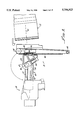
- FIG. 1 is a perspective view of a compact autoloader or ammunition transfer apparatus in accordance with the present invention, shown as it may be installed between a magazine and a gun which may be disposed on a combat vehicle, such as a tank, not shown;
- FIG. 2 is a side view of the transfer apparatus position for withdrawing an ammunition round from the magazine
- FIG. 3 is a side view of the transfer apparatus at a position for inserting a withdrawn inverted ammunition round into a gun chamber;
- FIG. 3a is a side view of the transfer apparatus at a position for inserting a withdrawn inverted ammunition round into a gun chamber with the gun at an elevation angle with respect to the magazine and horizontal;
- FIG. 4 is a front view of the transfer apparatus shown at the stow position
- FIG. 5 is a perspective view of a transfer unit in accordance with the present invention spaced apart from a carrier for engaging flanges for rotating the transfer unit;
- FIG. 6 is a side view of the transfer apparatus shown in a stow position between a magazine and a gun;
- FIG. 7 is perspective view of an opposite side of the transfer unit generally showing a rammer for movement of ammunition rounds within the transfer unit and case riders for maintaining alignment of the ammunition round as it is inserted into the gun chamber;
- FIG. 8 is a cross-sectional side view of the transfer unit with an ammunition round disposed therein;
- FIG. 9 is a partially broken away perspective view of the transfer unit showing an extractor having three dogs for engaging a base of an ammunition round;
- FIG. 10 is a cross-sectional view of the transfer unit showing an opposite side of the extractor, a cam and a pawl, for engaging a slot in the transfer unit housing for operation of the extractor, the view being shown with extractor dogs in a closed position;
- FIG. 11 is a view similar to FIG. 10 showing opened and closed positions of the extractor, the view being shown with extractor dogs in an open position;
- FIG. 12 is an exploded view of the extractor and a tic toc mechanism for controlling movement of the extractor dogs;
- FIG. 13 is a perspective view of the housing end showing the position of the tic toc mechanism for closure of the extracted dogs.
- FIG. 14 is a view similar to FIG. 13 showing the tic toc in a position for opening the extractor dogs for release of ammunition;
- FIGS. 15a-15f are stage wise depictions of the transfer unit inserting an ammunition round into a gun chamber and the function of the case riders for maintaining alignment.
- FIG. 1 there is shown ammunition transfer apparatus 10 in accordance with the present invention for moving ammunition rounds (not shown in FIG. 1) from a magazine 12 to a gun 14, and more particularly transfer means 18 for withdrawing ammunition rounds from the magazine 12, inverting a withdrawn ammunition round end to end, and inserting inverted withdrawn ammunition rounds into the gun 14, as herein described in greater detail.
- a reciprocating elevation drive means 20 disposed between the magazine 12 and the gun 14 for alternately moving the transfer means 18 into a first position for withdrawing ammunition rounds from the magazine (see FIG. 2) and a second position for inserting inverted withdrawn ammunition rounds into the gun 14 (see FIG. 3).
- the transfer means 18 includes a transfer unit 24 which provides a means for withdrawing ammunition rounds from the magazine 12 and inserting withdrawn ammunition rounds into the gun 14 and a carrier 26 which is attached to the reciprocating elevation drive means 20 and the transfer unit 24 for causing up to approximately a 180° rotation of the transfer unit 24 between the first and the second positions as shown respectively in FIGS. 2 and 3.
- the transfer unit 24 due to its elevational movement by the drive means 20 is operational for withdrawing ammunition from various spaced apart points or compartments of the magazine 12 and inserting the withdrawn ammunition rounds into the gun while the gun is at various elevations for commencement of fire, see FIG. 3a. This enhances the effective firing rate of the gun since a return to horizontal is not necessary for reloading thereof.
- the reciprocating drive means also provides for enabling access to the magazine 12 and the gun 14 at different elevations as shown by comparing the side views shown in FIGS. 2 and 3.
- a longitudinal axis 30 of the magazine may coincide with the longitudinal axis of the gun 32 or alternatively, as shown in the FIG. 3a, the longitudinal axes 30, 32 may be at an angle with one another.
- the drive means 20 be mounted for reciprocating the transfer unit 24 in directions generally perpendicular to the longitudinal axes 30, 32 as shown in the FIG. 3. It must also be appreciated that overhead constraints are also imposed because of a turret top (not shown) enclosing the apparatus 10.
- the magazine 12 may be any suitable type such as, for example, described in U.S. Pat. No. 4,928,574 for storing and transferring ammunition to a port 38 which provides a means for accessing ammunition rounds from the magazine 12 in which a longitudinal axis of the ammunition rounds (not shown) coincides with or is generally parallel with the longitudinal axis 32 of the gun.
- U.S. Pat. No. 4,928,574 is to be incorporated herewith, in toto, in order to fully describe a magazine suitable for use with the present invention.
- the reciprocating elevation drive means 20 may comprise of chains 40, drive sprockets 42 and idler sprockets 44 held in a spaced apart relationship by a frame 46 and driven by motors 48 in order to move the transfer unit 24 in reciprocating directions which are generally perpendicular to the longitudinal axis 32 of the gun 14.
- the carrier 26 includes elevation frames 50 disposed on two sides 52, 54 of the transfer unit 24, see also FIG. 4.
- the carrier 26 includes a pivot motor 58 including a drive shaft 60 coupled to a flange 62 in a conventional manner for rotating the transfer unit 24 during movement from the first to the second position.
- resolvers are preferably provided in order to provide data relating to the exact position and orientation of the transfer unit to a control system, not shown.
- the control system may be of any suitable electronic/computer programmable system for coordinating movement and control of not only the transfer apparatus 10 but the magazine 12 for providing various different rounds of ammunition at a specific time and for firing of the gun.
- transfer apparatus 10 in accordance with the present invention provides for selectively withdrawing a ammunition round (not shown) from magazine 12, inverting the ammunition round and inserting same into the gun 14 with no inhibition to the recoil movement of the gun 14 during firing.
- the mount 68 also serves to support the transfer means 18 during non-use thereof when electrical operating power thereto may be shut off.
- FIGS. 7 and 8 there is shown within a transfer unit housing a rammer 76 which is disposed for movement along and within housing 72 by means of drives sprockets 80 and chains 82 and idler sprockets 84 for moving ammunition rounds into and out of the transfer unit 24. Attachment of the rammer 76 to the chains 82 in any conventional manner provides for reciprocal motion of the rammer 76 within the transfer unit housing 72 during pick up of ammunition from the magazine 12 and delivery and insertion of the ammunition into the gun 14.
- FIG. 8 shows a typical ammunition round 86 is shown within the transfer unit housing 72 held at a base 88 by an extractor 106 which provides means for temporarily griping the ammunition round 86 in order to withdraw the ammunition round 86 from the magazine 12.
- the movement of the rammer 76 via the chain 82 is provided by a rammer motor 92 and are connected by gears 94, 96 and sprocket 86. Operation of the motor 92 including reversible action thereof as well as control and direction of the pivot motor and motors 46 (see FIG. 6) for elevational movement of transfer unit 24 are all coordinated by a properly programmed control system (not shown) suitable for coordinating required movements of the transfer apparatus 10.
- an extractor 100 provides a means for temporarily gripping ammunition on base 88 by a groove 104 (FIG. 8) for withdrawing the ammunition round 86 of the magazine 12.
- a groove 104 (FIG. 8) for withdrawing the ammunition round 86 of the magazine 12.
- Included in the extractor are a plurality of dogs 106 which are disposed for radial movement with respect to a longitudinal axes 110 of the transfer unit, within slots 112 which provide the cam means for causing the radial movement of the dogs 106 in response to linear movement of the rammer 76 and extractor 106 along the housing 72.
- This movement is provided by a pawl 116 integrally extending from a cam plate 118 which is guided by a slot 120 in a housing body 122.
- cam plate 118 Clockwise and anti-clockwise movement of cam plate 118 is affected through a tic toc mechanism 132 shown in FIGS. 11-14.
- the dogs 106 are slidably mounted in an extractor plate 134 and include ends 138 for engaging slots 112 in the cam plate 118.
- Extractor 100 is mounted to a front plate 142 on the rammer 76 by means of screws 144.
- a spring 146 disposed within a spring sleeve 148 enable support of the ammunition round 86 in an elevated gun 14 during release of the dogs 106 and before engagement of retainers, not shown, in the gun chamber to prevent rearward movement of the ammunition round 86 due to gravity.
- the tic toc mechanism 132 is pivotably mounted within a housing base 152 within a forward opening 154 and pivoted therein by means of a motor 158.
- a potentiometer 160 provides a signal to the control system (not shown) regarding the position of the tic toc 132 within the opening 154.
- the forward base 152 includes an entry slot 164 aligned with the slot 120 for smooth movement of the pawl 116 therein.
- FIGS. 7 through 9 Another important aspect of the present invention is shown in FIGS. 7 through 9 and illustrated in FIGS. 15a-15f.
- case riders 174 attach to the rammer drive chain 82 at a spaced apart distance from the extractor 100 provides a means for maintaining an alignment of the ammunition round 86 inserted into the gun 14 within a gun chamber 176. Such alignment is important in order to prevent jamming of the ammunition round 86 as it is forced into the gun chamber 176 by the rammer 76.
- the case riders 174 physically control movement a forward case portion 86a which is significantly smaller in diameter than a case rim 86b and withdraw from contact therewith via movement of the chains 82 to enable the case rim 86b to enter the gun chamber 176.
- the taper is more clearly seen in FIG. 8.
- the transfer unit housing 72 is at an inclined attitude with respect to the longitudinal axis 32 and accordingly upward movement of the ammunition round 86 may cause misalignment with gun chamber 176. It is to be appreciated that the diagram shown in FIGS. 15a-15f is greatly exaggerated only to emphasize the function of the case riders 174 in stabilizing and guiding the ammunition round 86 into the gun chamber 176.
- the transfer unit housing 73 lowers in elevation also maintaining, in combination with the cam riders 174, alignment of the ammunition round 86 with the gun chamber 176.
Landscapes
- Engineering & Computer Science (AREA)
- General Engineering & Computer Science (AREA)
- Portable Nailing Machines And Staplers (AREA)
- Braking Systems And Boosters (AREA)
- Crystals, And After-Treatments Of Crystals (AREA)
- Toys (AREA)
- Warehouses Or Storage Devices (AREA)
- Vending Machines For Individual Products (AREA)
- Preliminary Treatment Of Fibers (AREA)
Abstract
Description
Claims (26)
Priority Applications (6)
| Application Number | Priority Date | Filing Date | Title |
|---|---|---|---|
| US08/680,912 US5756923A (en) | 1996-07-12 | 1996-07-12 | Compact autoloader |
| EP97936954A EP0910781B1 (en) | 1996-07-12 | 1997-07-07 | Compact autoloader |
| AT97936954T ATE295524T1 (en) | 1996-07-12 | 1997-07-07 | COMPACT AUTOMATIC CHARGER |
| AU39586/97A AU3958697A (en) | 1996-07-12 | 1997-07-07 | Compact autoloader |
| PCT/US1997/011868 WO1998002703A1 (en) | 1996-07-12 | 1997-07-07 | Compact autoloader |
| DE69733257T DE69733257T2 (en) | 1996-07-12 | 1997-07-07 | COMPACT AUTOMATIC LOADING DEVICE |
Applications Claiming Priority (1)
| Application Number | Priority Date | Filing Date | Title |
|---|---|---|---|
| US08/680,912 US5756923A (en) | 1996-07-12 | 1996-07-12 | Compact autoloader |
Publications (1)
| Publication Number | Publication Date |
|---|---|
| US5756923A true US5756923A (en) | 1998-05-26 |
Family
ID=24733033
Family Applications (1)
| Application Number | Title | Priority Date | Filing Date |
|---|---|---|---|
| US08/680,912 Expired - Lifetime US5756923A (en) | 1996-07-12 | 1996-07-12 | Compact autoloader |
Country Status (6)
| Country | Link |
|---|---|
| US (1) | US5756923A (en) |
| EP (1) | EP0910781B1 (en) |
| AT (1) | ATE295524T1 (en) |
| AU (1) | AU3958697A (en) |
| DE (1) | DE69733257T2 (en) |
| WO (1) | WO1998002703A1 (en) |
Cited By (4)
| Publication number | Priority date | Publication date | Assignee | Title |
|---|---|---|---|---|
| US6694857B2 (en) * | 2000-02-18 | 2004-02-24 | Alvis Hagglunds Ab | Apparatus for discharging shells from an ammunition magazine, and a shell-discharging arrangement comprising two such apparatuses |
| US6772669B1 (en) * | 1999-09-23 | 2004-08-10 | Bofors Defence Aktiebolag | Method and arrangement for loading artillery pieces by means of flick ramming |
| KR100702939B1 (en) * | 2000-06-01 | 2007-04-03 | 삼성테크윈 주식회사 | Shell transporting apparatus and shell transporting method using the same |
| US8215225B1 (en) * | 2010-06-03 | 2012-07-10 | The United States Of America As Represented By The Secretary Of The Army | Large caliber autoloader |
Citations (9)
| Publication number | Priority date | Publication date | Assignee | Title |
|---|---|---|---|---|
| US3241447A (en) * | 1963-11-28 | 1966-03-22 | Bofors Ab | Cartridge ramming device of a gun |
| US4038906A (en) * | 1974-10-18 | 1977-08-02 | Ab Bofors | Method of and device for achieving a rapid transfer in a tank of a round from a magazine to the ramming position at the firearm of the tank |
| US4079659A (en) * | 1975-09-12 | 1978-03-21 | Ab Bofors | Device for transferring ammunition for tank |
| US4640181A (en) * | 1980-05-07 | 1987-02-03 | Kuka Wehrtechnik Gmbh | Automatic gun loading device for a tank |
| US4690031A (en) * | 1983-06-03 | 1987-09-01 | Rheinmetall Gmbh | Automatic loader for an armored vehicle having a rotatable turret |
| US4928574A (en) * | 1987-10-05 | 1990-05-29 | Western Design Corporation | Ammunition magazine system |
| US4947728A (en) * | 1988-03-08 | 1990-08-14 | Wegmann & Co. Gmbh | Combat vehicle, especially armored howitzer |
| US5196643A (en) * | 1990-04-04 | 1993-03-23 | Kuka Wehrtechnik Gmbh | Apparatus for loading tubular weapons, particularly tank howitzers |
| US5440966A (en) * | 1993-08-10 | 1995-08-15 | Fmc Corporation | Material hand-off device and process |
-
1996
- 1996-07-12 US US08/680,912 patent/US5756923A/en not_active Expired - Lifetime
-
1997
- 1997-07-07 AU AU39586/97A patent/AU3958697A/en not_active Abandoned
- 1997-07-07 EP EP97936954A patent/EP0910781B1/en not_active Expired - Lifetime
- 1997-07-07 WO PCT/US1997/011868 patent/WO1998002703A1/en active IP Right Grant
- 1997-07-07 DE DE69733257T patent/DE69733257T2/en not_active Expired - Lifetime
- 1997-07-07 AT AT97936954T patent/ATE295524T1/en not_active IP Right Cessation
Patent Citations (9)
| Publication number | Priority date | Publication date | Assignee | Title |
|---|---|---|---|---|
| US3241447A (en) * | 1963-11-28 | 1966-03-22 | Bofors Ab | Cartridge ramming device of a gun |
| US4038906A (en) * | 1974-10-18 | 1977-08-02 | Ab Bofors | Method of and device for achieving a rapid transfer in a tank of a round from a magazine to the ramming position at the firearm of the tank |
| US4079659A (en) * | 1975-09-12 | 1978-03-21 | Ab Bofors | Device for transferring ammunition for tank |
| US4640181A (en) * | 1980-05-07 | 1987-02-03 | Kuka Wehrtechnik Gmbh | Automatic gun loading device for a tank |
| US4690031A (en) * | 1983-06-03 | 1987-09-01 | Rheinmetall Gmbh | Automatic loader for an armored vehicle having a rotatable turret |
| US4928574A (en) * | 1987-10-05 | 1990-05-29 | Western Design Corporation | Ammunition magazine system |
| US4947728A (en) * | 1988-03-08 | 1990-08-14 | Wegmann & Co. Gmbh | Combat vehicle, especially armored howitzer |
| US5196643A (en) * | 1990-04-04 | 1993-03-23 | Kuka Wehrtechnik Gmbh | Apparatus for loading tubular weapons, particularly tank howitzers |
| US5440966A (en) * | 1993-08-10 | 1995-08-15 | Fmc Corporation | Material hand-off device and process |
Cited By (4)
| Publication number | Priority date | Publication date | Assignee | Title |
|---|---|---|---|---|
| US6772669B1 (en) * | 1999-09-23 | 2004-08-10 | Bofors Defence Aktiebolag | Method and arrangement for loading artillery pieces by means of flick ramming |
| US6694857B2 (en) * | 2000-02-18 | 2004-02-24 | Alvis Hagglunds Ab | Apparatus for discharging shells from an ammunition magazine, and a shell-discharging arrangement comprising two such apparatuses |
| KR100702939B1 (en) * | 2000-06-01 | 2007-04-03 | 삼성테크윈 주식회사 | Shell transporting apparatus and shell transporting method using the same |
| US8215225B1 (en) * | 2010-06-03 | 2012-07-10 | The United States Of America As Represented By The Secretary Of The Army | Large caliber autoloader |
Also Published As
| Publication number | Publication date |
|---|---|
| DE69733257T2 (en) | 2006-01-26 |
| ATE295524T1 (en) | 2005-05-15 |
| EP0910781B1 (en) | 2005-05-11 |
| EP0910781A4 (en) | 2001-04-18 |
| AU3958697A (en) | 1998-02-09 |
| WO1998002703A1 (en) | 1998-01-22 |
| EP0910781A1 (en) | 1999-04-28 |
| DE69733257D1 (en) | 2005-06-16 |
Similar Documents
| Publication | Publication Date | Title |
|---|---|---|
| US4614052A (en) | Firearm magazine and magazine loader | |
| CA1300948C (en) | Method and apparatus for orienting and loading rim-fire cartridges | |
| US4676137A (en) | Weapon firearm with magazine | |
| WO1989004454A1 (en) | Method and apparatus for orienting and loading cartridges | |
| AU649738B2 (en) | Firearm | |
| US20030168053A1 (en) | Paintball loader | |
| JPS6244200B2 (en) | ||
| EP0205661A2 (en) | Loader for small-arms magazines | |
| US4727790A (en) | Automated shell loading apparatus for externally mounted tank cannon | |
| CA2242887C (en) | System for the loading of a mortar | |
| US5756923A (en) | Compact autoloader | |
| EP0058814B1 (en) | Vertical loading system for a gun mount | |
| DE50309631D1 (en) | SHOOTING MODULE | |
| EP0195093B1 (en) | Ammunition magazine | |
| KR930002792A (en) | Tank gun autoloader | |
| DE3167597D1 (en) | Firearms with rotary magazines | |
| US5261310A (en) | Apparatus for autoloading tank cannons | |
| USH164H (en) | High capacity magazine for weapons | |
| JPS61501720A (en) | Device for delivering and loading bullets into a weapon in any direction and at any height | |
| USH1121H (en) | Primer feed mechanism | |
| JPS63217198A (en) | Charger for cylindrical firearm | |
| US5610362A (en) | Ammunition feed device and method | |
| US7500326B2 (en) | Manually loaded magazine pistol | |
| US7228779B2 (en) | Automatic primer feed mechanism | |
| US3894471A (en) | Rapid fire weapon for turret installation |
Legal Events
| Date | Code | Title | Description |
|---|---|---|---|
| AS | Assignment |
Owner name: WESTERN DESIGN CORPORATION, CALIFORNIA Free format text: ASSIGNMENT OF ASSIGNORS INTEREST;ASSIGNORS:GOLDEN, MICHAEL D.;YU, DINO K.;REEL/FRAME:008108/0525 Effective date: 19960710 |
|
| STCF | Information on status: patent grant |
Free format text: PATENTED CASE |
|
| FEPP | Fee payment procedure |
Free format text: PAYOR NUMBER ASSIGNED (ORIGINAL EVENT CODE: ASPN); ENTITY STATUS OF PATENT OWNER: LARGE ENTITY |
|
| FPAY | Fee payment |
Year of fee payment: 4 |
|
| FPAY | Fee payment |
Year of fee payment: 8 |
|
| AS | Assignment |
Owner name: MEGGITT DEFENSE SYSTEMS, INC.,CALIFORNIA Free format text: ASSIGNMENT OF ASSIGNORS INTEREST;ASSIGNOR:WESTERN DESIGN CORPORATION;REEL/FRAME:018584/0289 Effective date: 20061129 Owner name: MEGGITT DEFENSE SYSTEMS, INC., CALIFORNIA Free format text: ASSIGNMENT OF ASSIGNORS INTEREST;ASSIGNOR:WESTERN DESIGN CORPORATION;REEL/FRAME:018584/0289 Effective date: 20061129 |
|
| FPAY | Fee payment |
Year of fee payment: 12 |