EP0331142B1 - Numerisch gesteuerte Einrichtung mit Kompensierung für toten Gang - Google Patents
Numerisch gesteuerte Einrichtung mit Kompensierung für toten Gang Download PDFInfo
- Publication number
- EP0331142B1 EP0331142B1 EP89103571A EP89103571A EP0331142B1 EP 0331142 B1 EP0331142 B1 EP 0331142B1 EP 89103571 A EP89103571 A EP 89103571A EP 89103571 A EP89103571 A EP 89103571A EP 0331142 B1 EP0331142 B1 EP 0331142B1
- Authority
- EP
- European Patent Office
- Prior art keywords
- lost motion
- motor
- servo
- amount
- control device
- Prior art date
- Legal status (The legal status is an assumption and is not a legal conclusion. Google has not performed a legal analysis and makes no representation as to the accuracy of the status listed.)
- Expired - Lifetime
Links
Images


Classifications
-
- G—PHYSICS
- G05—CONTROLLING; REGULATING
- G05B—CONTROL OR REGULATING SYSTEMS IN GENERAL; FUNCTIONAL ELEMENTS OF SUCH SYSTEMS; MONITORING OR TESTING ARRANGEMENTS FOR SUCH SYSTEMS OR ELEMENTS
- G05B19/00—Programme-control systems
- G05B19/02—Programme-control systems electric
- G05B19/18—Numerical control [NC], i.e. automatically operating machines, in particular machine tools, e.g. in a manufacturing environment, so as to execute positioning, movement or co-ordinated operations by means of programme data in numerical form
- G05B19/404—Numerical control [NC], i.e. automatically operating machines, in particular machine tools, e.g. in a manufacturing environment, so as to execute positioning, movement or co-ordinated operations by means of programme data in numerical form characterised by control arrangements for compensation, e.g. for backlash, overshoot, tool offset, tool wear, temperature, machine construction errors, load, inertia
-
- G—PHYSICS
- G05—CONTROLLING; REGULATING
- G05B—CONTROL OR REGULATING SYSTEMS IN GENERAL; FUNCTIONAL ELEMENTS OF SUCH SYSTEMS; MONITORING OR TESTING ARRANGEMENTS FOR SUCH SYSTEMS OR ELEMENTS
- G05B2219/00—Program-control systems
- G05B2219/30—Nc systems
- G05B2219/41—Servomotor, servo controller till figures
- G05B2219/41043—Memory table with motor current and corresponding correction for lost motion
Definitions
- NC devices numerical control devices
- an NC device such as a numerically controlled (NC) machine tool
- NC numerically controlled
- a semi-closed loop system which is one example of a servo loop system for a numerically controlled (NC) machine tool.
- the torque of the servo motor is converted into a linear motion by a ball thread feed drive mechanism to linearly move a movable part of the NC machine tool, and in this operation, the position control of the movable part is carried out as follows:
- the position detection of the movable part is not made at its end; that is, the angle of rotation of the movable part is detected with a detector coupled to the end of the ball thread or the drive motor thereby to indirectly detect the position of the movable part.
- the feed drive mechanism is "twisted” or “bent” depending on a load applied thereto.
- the stop position of the movable part when positioned in place in a forward (positive) direction will differ from that of the movable part when positioned in a reverse (negative) direction.
- a method has been employed in which the value with the feed speed set to about 100 mm/min, the difference is measured, and it is applied, as a backlash correcting value including a lost motion correcting value, to the NC device, to correct the amount of mechanical movement.
- the lost motion which is one of the factors causing the difference between the two stop positions, attributes to a mechanism different from the play (backlash) of the ball thread in the drive system.
- a linearly movable part such as a table, saddle or slide in a machine tool (hereinafter referred to as "a table”, when applicable, for simplification in description) in brief.
- FIG. 9 shows the arrangement of a general ball thread feed drive mechanism.
- the ball thread feed drive mechanism comprises a number of mechanical components such as a ball thread, bearings, brackets, and parts for mounting and securing these components.
- various parts are displaced by a torque of the drive motor, and by the load of the system.
- the torque of the drive motor is transmitted through a coupling to the ball thread shaft to which tension has been given in advance to improve its rigidity, and to the nut section combined with the ball thread shaft, thus linearly driving the table which is fixedly secured to the nut section and is supported by linear bearings.
- the bearing section supporting the ball thread shaft and the linear bearing section supporting the table are suitably pre-loaded, thus providing their best mechanical characteristics.
- the frictions affecting the torque is greatly changed by the pre-load, the viscosity and quantity of lubricant used, and the feed speed.
- the displacement in motion position of the table attributing to the torque depends on the displacement (elastic deformation) of the various parts, the ball thread, the ball thread shaft, the bracket section, and the stationary structure of the motor drive system.
- the twisting and bending of the ball thread shaft being the function of the length between the drive section and the nut section, can be expressed as follows: ⁇ SM Tw ⁇ k L ⁇ S N ⁇ M Tw + ⁇ S M ⁇ M Tw + ⁇ S B ⁇ M Tw + ⁇ S ⁇ S M Tw + ⁇ S ⁇ C
- This displacement changes with the torque; that is, it changes when the speed of the table is increased from substantially zero (at rest) at around the speed of feed used for actual work, thus being proportional to the variations in the position of the table, the inertial moments of the moving parts, and the coefficients of frictions of the bearing sections and the table.
- the displacement mentioned above may be disregarded when the structure is made sufficiently rigid against the load. However, in the case where it is impossible to increase the rigidity because of the mechanical structure or manufacturing cost, sometimes those of the resultant machine are considerably large.
- the torque is inverted in direction, and the table coupled through the ball thread to the servo motor will not be moved even if the servo motor rotates as much as the sum of the displacement in the forward direction and that in the reverse direction (two times the amount of displacement ⁇ SM Tw ).
- the amount of correction of backlash which has been initially measured and set with the speed of feed of about 100 mm/min, is not that which is determined by taking into account the speed of the feed, the load on the table, and the length of the ball thread from the drive section. Accordingly, the positioning effected under the conditions different from those preset is not sufficiently high in accuracy.
- FIG. 10 is a graphical representation indicating the follow-up characteristics of an NC machine tool.
- FIGS. 11 and 12 are also graphical representation generally indicating amounts of lost motion with speed of feed.
- a conventional NC machine tool has the lost motion which changes essentially with machining conditions; however, it has no means for detecting only the lost motion. Accordingly, the NC device itself has no function of correcting the lost motion, and the correction has been performed in terms of backlash correction. Thus, whenever the machining conditions change, the machining accuracy is changed. Recently, there has been a strong demand for the provision of a stable and accurate machining technique, and accordingly for the correction of lost motion.
- the present inventors have found it through experiments that the drive current of the servo motor can provide data sufficiently high in accuracy for detection of the above-described torque without provision or a particular sensor.
- An object of the present invention is to provide a numerical control device which is capable of correcting position errors caused by lost motion with high accuracy.
- a numerical control device comprising: motor current detecting means for detecting at a given time the drive current of a servo-motor in a servo-system for servo-controlling a mechanical system; means having a table which includes values which relate the motor current of said servo motor to the corresponding amount of lost motion correction; said means using a motor current dtected at a given time instant by said motor current detecting means and utilizing the result of said calculation, to correct the lost motion of said mechanical system.
- a numerical control device comprising: motor current detecting means for detecting at a given time the drive current of a servo motor in a servo system for servo-controlling a movable part of a mechanical system; and means having a function representing a drive current of said servo motor and the amount of lost motion correction corresponding thereto, for calculating an amount of lost motion correction according to said function by using a motor current detected at a given time instant by said motor current detection means, to correct the lost motion of said moveable part.
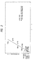
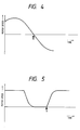
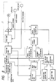
- FIGS. 1 through 5 are diagrams for a description of a first embodiment of this motion correction based on the drive current detected at a given time instant by said motor current detection means and the distance stored in said storing means, to correct the lost motion of said mechanical system. More specifically, FIG. 1 is a graphical representation indicating amounts of lost motion with motor output torque in an arc interpolation; FIG. 2 is a graphical representation indicating amounts of lost motion with motor output torque in a linear interpolation; FIG. 3 is a block diagram showing the arrangement of a numerical control device for the correction of lost motion, which is a first embodiment of this invention; FIG. 4 is a graphical representation showing the time instant the motor feedback speed is inverted; and FIG.
- FIG. 5 is a graphical representation showing the time instant the motor starts movement.
- FIG. 6 is a block diagram showing the arrangement of a numerical control device for the correction of lost motion, which is a second embodiment of the invention.
- FIG. 7 is a block diagram showing the arrangement of one application of the numerical control device shown in FIG. 3.
- FIG. 8 is a block diagram showing the arrangement of one application of the numerical control device shown in FIG. 3.
- FIG. 9 is an explanatory diagram showing a general ball thread feed drive mechanism.
- FIG. 10 is a graphical representation indicating the follow-up characteristics of a machine.
- FIGS. 11 and 12 are graphical representation indicating general relations between amounts of lost motion and feed speeds.
- the lost motion phenomenon results from the elastic deformation of the feed system and stationary structure of the NC machine tool, and therefore its magnitude is changed by the frictional resistance of the table. Accordingly, the backlash correcting function of applying a predetermined correcting pulse at the time of reversing the direction of motion is insufficient to correct the lost motion. Therefore, in the invention, research is conducted on the relationship between amounts of lost motion and servo motor drive currents (hereinafter referred to merely as "drive currents", when applicable) in advance, and the lost motion correction is carried out according to the relationship thus researched.
- drive currents servo motor drive currents
- FIG. 1 is a graphical representation indicating amounts of lost motion with drive currents in an arc interpolation.
- the graphical representation is obtained by measuring from the result of experiments the torque provided immediately before the direction of motion is reversed and the amount of lost motion at that time instant, and by plotting those data for each speed.
- the drive current relates linearly to the amount of lost motion.
- FIG. 2 shows relationships between amounts of lost motion and drive currents when, in a quick feed or linear interpolation, the movable part is at rest. In this case also, a linear relation is established between the amount of lost motion and the drive current.
- reference numeral 1 designates an acceleration and deceleration control device which receives interpolation data such as movement increment data, and performs the acceleration and deceleration control of a primary delay circuit for instance, and outputs a speed instruction for the motor; 2, a servo mechanism for performing the positioning control of the motor according to the output of the acceleration and deceleration control device 1; 3, a motor feedback speed memory device for storing a motor feedback speed (data) outputted by the servo mechanism 2; 4, a speed inversion discriminator for receiving the motor feedback speed stored in the motor feedback speed memory device, to determine whether or not the motor feedback speed is inverted in polarity, and 5, a movement start discriminator for receiving the motor feedback speed from the motor feedback speed memory device 3, to determine whether or not the motor movement is started.
- reference numeral 6 designates a motor feedback current memory device for storing a motor feedback current (data) outputted by the servo mechanism 2; 7, proportional constant memory device for storing the proportional constant of a motor feedback current value and an amount of lost motion; and 8, a constant term memory device for storing the constant term in the proportion relation of a motor feedback current value and an amount of lost motion.
- the proportional constant memory device 7 and the constant term memory device 8 are RAMs (random access memories) in which the numerical values of the proportional constant and of the constant term are loaded for instance through a keyboard.
- reference numeral 9 designates a lost motion correction data calculating device having a table/function means, the device 9 receiving the data stored in the proportional constant memory device, the constant term memory device, and the motor feedback current memory device 6, to calculate an amount of lost motion correction.
- the latter 2 control the motor according to the data applied thereto.
- the motor feedback speed is sampled and applied to the motor feedback speed memory device 3.
- the speed inversion discriminator 4 obtains for instance the product of a motor feedback speed sampled and that sampled before it by receiving them from the motor feedback speed memory device 3, and determines whether or not the product is, for instance, negative, thereby to obtain the time instant ( a in FIG. 4) where the motor feedback speed is inverted in polarity, and applies a motor feedback current value sampling instruction to the motor feedback current memory device 6.
- the movement start discriminator 5 receives motor feedback speeds from the motor feedback speed memory device 3 to determine, for instance, whether or not a motor feedback speed sampled is zero and that sampled before it is not zero, thereby to obtain the time instant ( b in FIG. 5) where the motor starts movement, and applies a motor feedback current value sampling instruction to the motor feedback current memory device 6.
- the motor feedback current memory 6 samples the motor feedback current outputted by the servo mechanism 2, and applies it to the lost motion correction data calculating device 9.
- the calculating device 9 applies the motor feedback current value applied thereto by the motor feedback current memory device 6 and the data stored in the proportional constant memory device 7 and the constant term memory device 8 to the table/function means built in it, to obtain an amount of lost motion correction ⁇ .
- the amount of lost motion correction obtained by the lost motion correction data calculating device 9 together with the output of the acceleration and deceleration control device 1 is applied to the servo mechanism 2.
- FIG. 6 shows another embodiment of the invention.
- reference numeral 10 designates a speed instruction memory device; and 11, a delay element.
- position data such as speed instruction applied to the servo mechanism 2 by the acceleration and deceleration control device 1
- adjustment is made with the delay element with the aid of the servo mechanism.
- FIG. 7 shows one application of the embodiment illustrated in FIG. 3.
- reference numeral 12 designates a position memory device 12, which stores the distance between the ball thread device section and the nut section.
- FIG. 8 shows one application of the second embodiment illustrated in FIG. 6.
- reference numeral 12 designates a position memory device, which stores the length between the ball thread drive section and the nut section.
- the operation of the circuit shown in FIG. 8 is substantially similar to that of the circuit shown in FIG. 6.
- the amount of lost motion correction is obtained according to equation (5).
- the relation of proportion is established between the amount of lost motion correction and the drive current; however it goes without saying that, when a different relation is held therebetween, the correction can be made by use of the functional equation corresponding thereto.
- the relation between the drive current and the amount of lost motion correction is obtained through the table/function.
- the relation between the drive current and the amount of lost motion correction stored may be stored in table means (memory device) so as to be used as data, or the table means may be combined with the function, for the same effect.
- the RAMs are employed as the proportional constant memory device 7 and the constant term memory device 8; however, it goes without saying that ROMs (read-only memories) may be used therefor.
- logic circuits may be employed for the above-described data storing or calculating operations.
- the numerical control device of the invention has the table/function representing the drive current of the servo motor at a given time instant and the corresponding amount of lost motion correction, and the means for utilizing the drive current at the given time instant which is detected by the drive current detecting means to correct the lost motion according to the table/function is operation for the correction of lost motion. Therefore, with the numerical control device of the invention, the position error caused by the lost motion can be corrected with high accuracy. If necessary, the length between the drive section and the nut section can be utilized for the correction of lost motion, and accordingly, the machining operation can be achieved with higher accuracy.
Landscapes
- Engineering & Computer Science (AREA)
- Human Computer Interaction (AREA)
- Manufacturing & Machinery (AREA)
- Physics & Mathematics (AREA)
- General Physics & Mathematics (AREA)
- Automation & Control Theory (AREA)
- Numerical Control (AREA)
- Control Of Position Or Direction (AREA)
Claims (3)
- Numerische Steuereinrichtung mit:
einem Motorstromdetektor (6) zur Feststellung des Antriebsstromes eines Servomotors (2) in einem Servosystem zur Servosteuerung eines mechanischen Systems zu einer bestimmten Zeit;
einer Einrichtung (9), die eine Tabelle enthält, welche den Motorstrom des Servomotors (2) mit dem entsprechenden Korrekturwert des toten Ganges verknüpft;
wobei diese Einrichtung (9) den zu einem bestimmten Zeitpunkt durch den Motorstromdetektor (6) festgestellten Motorstrom zu einer Berechnung verwendet, um mit deren Ergebnis den toten Gang des mechanischen Systems zu korrigieren. - Numerische Steuereinrichtung mit
einem Motorstromdetektor (6) zur Feststellung des Antriebsstromes eines Servomotors (2) in einem Servosystem zur Servosteuerung eines beweglichen Teils in einem mechanischen System zu einer bestimmten Zeit
und
einer Einrichtung (9) mit einer Funktion, die einen Antriebsstrom des Servomotors und den diesem entsprechenden Korrekturwert des toten Ganges darstellt, um einen Korrekturwert des toten Ganges entsprechend dieser Funktion unter Verwendung des zu einem bestimmten Zeitpunkt durch den Motorstromdetektor (6) festgestellten Motorstromes zu berechnen und den toten Gang des beweglichen Teils des mechanischen Systems zu korrigieren. - Numerische Steuereinrichtung nach Anspruch 2, bei der das mechanische System eine Kugelspindel und einen Mutterbereich aufweist, der funktionell mit der Kugelspindel verbunden ist;
bei der eine Einrichtung (12) zur Speicherung des Abstandes des Mutterbereichs auf der Torsion und Durchbiegung unterliegenden Kugelspindel vorgesehen ist
und die Recheneinrichtung (9) einen Korrekturwert des toten Ganges auf der Grundlage des vom Motorstromdetektor (6) zu einem bestimmten Zeitpunkt festgestellten Antriebsstromes und des in der Speichereinrichtung (12) gespeicherten Abstandes berechnet, um den toten Gang des Mutterbereichs zu korrigieren.
Applications Claiming Priority (2)
| Application Number | Priority Date | Filing Date | Title |
|---|---|---|---|
| JP48118/88 | 1988-03-01 | ||
| JP63048118A JPH0833763B2 (ja) | 1988-03-01 | 1988-03-01 | 数値制御装置 |
Publications (3)
| Publication Number | Publication Date |
|---|---|
| EP0331142A2 EP0331142A2 (de) | 1989-09-06 |
| EP0331142A3 EP0331142A3 (en) | 1990-10-17 |
| EP0331142B1 true EP0331142B1 (de) | 1994-08-31 |
Family
ID=12794409
Family Applications (1)
| Application Number | Title | Priority Date | Filing Date |
|---|---|---|---|
| EP89103571A Expired - Lifetime EP0331142B1 (de) | 1988-03-01 | 1989-03-01 | Numerisch gesteuerte Einrichtung mit Kompensierung für toten Gang |
Country Status (6)
| Country | Link |
|---|---|
| US (1) | US4961034A (de) |
| EP (1) | EP0331142B1 (de) |
| JP (1) | JPH0833763B2 (de) |
| KR (1) | KR910007054B1 (de) |
| DE (1) | DE68917754T2 (de) |
| HK (1) | HK1004297A1 (de) |
Cited By (1)
| Publication number | Priority date | Publication date | Assignee | Title |
|---|---|---|---|---|
| US6166508A (en) * | 1996-08-09 | 2000-12-26 | Brose Fahrzeugteile Gmbh & Co. Kg | Process for controlling the displacement of the window pane of a motor vehicle door |
Families Citing this family (19)
| Publication number | Priority date | Publication date | Assignee | Title |
|---|---|---|---|---|
| JP2762364B2 (ja) * | 1989-03-20 | 1998-06-04 | ファナック株式会社 | サーボモータのフィードフォワード制御方法 |
| JPH0371206A (ja) * | 1989-08-10 | 1991-03-27 | Mitsubishi Electric Corp | Nc工作機械の機械誤差補正装置 |
| JP2935713B2 (ja) * | 1989-08-22 | 1999-08-16 | ファナック株式会社 | 数値制御装置 |
| JPH03180909A (ja) * | 1989-12-11 | 1991-08-06 | Mitsubishi Electric Corp | 数値制御装置 |
| JPH03246707A (ja) * | 1990-02-26 | 1991-11-05 | Fanuc Ltd | 系統別位置補正方式 |
| JPH03290706A (ja) * | 1990-04-09 | 1991-12-20 | Mitsubishi Electric Corp | 数値制御装置 |
| JP2636087B2 (ja) * | 1991-03-28 | 1997-07-30 | 松下電器産業株式会社 | 部品供給方法 |
| JPH0667716A (ja) * | 1992-08-19 | 1994-03-11 | Mitsubishi Electric Corp | 数値制御装置並びに数値制御方法 |
| JP3481004B2 (ja) * | 1995-02-02 | 2003-12-22 | ファナック株式会社 | 外乱オブザーバを使用したバックラッシュ補正方法 |
| KR100241148B1 (ko) * | 1995-07-13 | 2000-03-02 | 이종수 | 수치 제어기의 백래시 보정 장치 및 그 방법 |
| DE19632910C2 (de) * | 1996-08-16 | 2002-07-25 | Brose Fahrzeugteile | Verfahren zum berührungslosen Anfahren der unteren Anschlagsposition einer fremdkraftbetätigten Fensterscheibe eines Kraftfahrzeugs |
| JP3169838B2 (ja) * | 1996-08-21 | 2001-05-28 | 東芝機械株式会社 | サーボモータの制御方法 |
| DE19711979A1 (de) | 1997-03-12 | 1998-10-08 | Brose Fahrzeugteile | Verfahren zur elektrischen Steuerung und Regelung der Bewegung von elektrisch betriebenen Aggregaten |
| JP2001166805A (ja) * | 1999-12-13 | 2001-06-22 | Toshiba Mach Co Ltd | ハイブリッド制御方式の工作機械のロストモーション補正値設定方法およびその方法をコンピュータに実行させるプログラムを記録したコンピュータ読み取り可能な記録媒体および数値制御工作機械 |
| JP2004533909A (ja) * | 2001-07-13 | 2004-11-11 | コーニンクレッカ フィリップス エレクトロニクス エヌ ヴィ | 動作データを記憶する記憶手段を有するフードプロセッサ |
| JP2004280506A (ja) * | 2003-03-17 | 2004-10-07 | Fanuc Ltd | 数値制御装置 |
| JP4510723B2 (ja) * | 2005-08-22 | 2010-07-28 | オークマ株式会社 | ロストモーション補正機能を有する位置制御装置 |
| JP5991249B2 (ja) * | 2013-03-27 | 2016-09-14 | ブラザー工業株式会社 | 数値制御装置 |
| US11385139B2 (en) | 2018-11-21 | 2022-07-12 | Martin E. Best | Active backlash detection methods and systems |
Family Cites Families (27)
| Publication number | Priority date | Publication date | Assignee | Title |
|---|---|---|---|---|
| JPS4835259A (de) * | 1971-09-10 | 1973-05-24 | ||
| US3866212A (en) * | 1973-10-23 | 1975-02-11 | Giddings & Lewis | Position control system with plural signal transmission through common inductive device |
| US4081732A (en) * | 1976-03-02 | 1978-03-28 | Tadamasa Aoyama | Automatic positioning method and apparatus |
| US4478009A (en) * | 1978-05-09 | 1984-10-23 | Rukavina Daniel M | Automatic control system for machine tools |
| JPS5776608A (en) * | 1980-10-30 | 1982-05-13 | Fanuc Ltd | Position error correction device |
| US4341986A (en) * | 1981-01-22 | 1982-07-27 | The United States Of America As Represented By The Secretary Of The Navy | Servo control system for the positioning of an apparatus |
| DE3121048A1 (de) * | 1981-05-27 | 1982-12-16 | Licentia Patent-Verwaltungs-Gmbh, 6000 Frankfurt | Anordnung zur steuerung der geschwindigkeit eines von einem antrieb bewegbaren gegenstands |
| GB2103833B (en) * | 1981-06-17 | 1984-11-14 | Renishaw Electrical Ltd | Numerically controlled machine tool |
| JPS5846413A (ja) * | 1981-09-14 | 1983-03-17 | Hitachi Ltd | 電気サ−ボ機構 |
| US4459525A (en) * | 1982-02-03 | 1984-07-10 | Ricoh Company, Ltd. | Motor speed control system |
| US4506321A (en) * | 1982-09-08 | 1985-03-19 | Imec Corporation | Motion control system with adaptive deceleration |
| JPS5947985A (ja) * | 1982-09-13 | 1984-03-17 | Ricoh Co Ltd | サ−ボモ−タの速度制御方式 |
| JPS5981705A (ja) * | 1982-11-02 | 1984-05-11 | Fanuc Ltd | Nc工作機械における補正方法 |
| DE3306555C2 (de) * | 1983-02-25 | 1986-03-27 | Brown, Boveri & Cie Ag, 6800 Mannheim | Regeleinrichtung für Werkzeugmaschinen mit einer durch einen Motor über ein Schaltgetriebe angetriebenen Arbeitsspindel od. dgl. |
| JPS59161708A (ja) * | 1983-03-04 | 1984-09-12 | Fanuc Ltd | サ−ボ駆動ユニツト |
| JPS59197901A (ja) * | 1983-04-25 | 1984-11-09 | Canon Inc | 運動制御装置 |
| EP0126388B1 (de) * | 1983-05-13 | 1989-11-08 | Hitachi, Ltd. | Verfahren zur Steuerung einer numerisch gesteuerten Werkzeugmaschine |
| JPS602088A (ja) * | 1983-06-15 | 1985-01-08 | Ricoh Co Ltd | サ−ボモ−タ駆動方式 |
| US4578763A (en) * | 1983-08-15 | 1986-03-25 | International Cybernetics Corp. | Sampled data servo control system with deadband compensation |
| US4574227A (en) * | 1983-11-14 | 1986-03-04 | Datapoint Corporation | Dual mode servo |
| DE3408551A1 (de) * | 1984-03-08 | 1985-09-12 | Siemens AG, 1000 Berlin und 8000 München | Verfahren zum verringern von bahnfehlern bei rechnergesteuerten werkzeugmaschinen oder industrierobotern |
| AU549174B2 (en) * | 1984-05-08 | 1986-01-16 | Matsushita Electric Industrial Co., Ltd. | Control system for dc motors |
| JPS6190205A (ja) * | 1984-10-09 | 1986-05-08 | Komatsu Ltd | ロボツトの絶対位置決め誤差補償方法 |
| US4698569A (en) * | 1985-06-13 | 1987-10-06 | Yoshikazu Kimura | Apparatus for locating a carrier at a desired position |
| US4713596A (en) * | 1985-07-10 | 1987-12-15 | General Electric Company | Induction motor drive system |
| JPS6294251A (ja) * | 1985-10-17 | 1987-04-30 | Toshiba Mach Co Ltd | 位置制御装置 |
| JPS63123605A (ja) * | 1986-11-12 | 1988-05-27 | Fanuc Ltd | タツピング加工制御装置 |
-
1988
- 1988-03-01 JP JP63048118A patent/JPH0833763B2/ja not_active Expired - Lifetime
-
1989
- 1989-02-25 KR KR1019890002255A patent/KR910007054B1/ko not_active IP Right Cessation
- 1989-03-01 DE DE68917754T patent/DE68917754T2/de not_active Expired - Lifetime
- 1989-03-01 EP EP89103571A patent/EP0331142B1/de not_active Expired - Lifetime
- 1989-03-01 US US07/317,390 patent/US4961034A/en not_active Expired - Lifetime
-
1998
- 1998-04-28 HK HK98103588A patent/HK1004297A1/xx not_active IP Right Cessation
Cited By (1)
| Publication number | Priority date | Publication date | Assignee | Title |
|---|---|---|---|---|
| US6166508A (en) * | 1996-08-09 | 2000-12-26 | Brose Fahrzeugteile Gmbh & Co. Kg | Process for controlling the displacement of the window pane of a motor vehicle door |
Also Published As
| Publication number | Publication date |
|---|---|
| JPH0833763B2 (ja) | 1996-03-29 |
| EP0331142A2 (de) | 1989-09-06 |
| HK1004297A1 (en) | 1998-11-20 |
| KR910007054B1 (ko) | 1991-09-16 |
| DE68917754T2 (de) | 1995-02-16 |
| JPH01222302A (ja) | 1989-09-05 |
| EP0331142A3 (en) | 1990-10-17 |
| US4961034A (en) | 1990-10-02 |
| DE68917754D1 (de) | 1994-10-06 |
| KR890015098A (ko) | 1989-10-28 |
Similar Documents
| Publication | Publication Date | Title |
|---|---|---|
| EP0331142B1 (de) | Numerisch gesteuerte Einrichtung mit Kompensierung für toten Gang | |
| US5952804A (en) | Servo control method and servo control system for feed drive system | |
| EP0460224B1 (de) | Verfahren zur steuerung eines servomotors | |
| JP3215067B2 (ja) | 移動方向反転時の位置補正方法 | |
| US6566835B1 (en) | Nc machine tool, and method of controlling nc machine tool | |
| US7571669B2 (en) | Machining apparatus for noncircular shapes | |
| EP0557530A1 (de) | Numerische steuerungseinrichtung | |
| KR910006500B1 (ko) | 서어보모터 제어장치 | |
| EP0277656B1 (de) | Vorrichtung zur genauen Positionierung | |
| KR890015099A (ko) | 공작기계 에러보정장치 | |
| EP1505463B1 (de) | Vorrichtung zur Positionssteuerung und Verfahren zur Positionssteuerung für Werkzeugmaschinen | |
| KR20120127061A (ko) | 공작기계의 백래시 자동 검출과 보상을 위한 방법 및 장치 | |
| KR910006499B1 (ko) | 수치 제어장치 | |
| US5513114A (en) | Apparatus for and method of compensating for positioning error | |
| KR100450455B1 (ko) | 서보 제어 방법 | |
| US5517100A (en) | Method of controlling a servo motor | |
| JP3811088B2 (ja) | サーボ制御方法 | |
| JP2002023852A (ja) | 数値制御工作機械の送り機構の補正装置および数値制御工作機械 | |
| JPH06225565A (ja) | 電動機駆動系の慣性負荷測定方式 | |
| Suzuki et al. | A stick motion compensation system with a dynamic model | |
| JP3246572B2 (ja) | 電動機駆動系の負荷定数測定方法 | |
| JP2777759B2 (ja) | 推力適応制御機能を備えた電気式推力発生装置 | |
| JPH05318257A (ja) | 工具交換装置 | |
| JPH01193140A (ja) | 送りねじのバツクラツシユ補正方法 | |
| JPH0446715B2 (de) |
Legal Events
| Date | Code | Title | Description |
|---|---|---|---|
| PUAI | Public reference made under article 153(3) epc to a published international application that has entered the european phase |
Free format text: ORIGINAL CODE: 0009012 |
|
| AK | Designated contracting states |
Kind code of ref document: A2 Designated state(s): DE FR GB |
|
| PUAL | Search report despatched |
Free format text: ORIGINAL CODE: 0009013 |
|
| AK | Designated contracting states |
Kind code of ref document: A3 Designated state(s): DE FR GB |
|
| 17P | Request for examination filed |
Effective date: 19901205 |
|
| 17Q | First examination report despatched |
Effective date: 19921204 |
|
| RAP3 | Party data changed (applicant data changed or rights of an application transferred) |
Owner name: IHARA, YUKITOSHI Owner name: KAKINO, YOSHIAKI, DR. Owner name: MITSUBISHI DENKI KABUSHIKI KAISHA |
|
| RBV | Designated contracting states (corrected) |
Designated state(s): DE GB |
|
| GRAA | (expected) grant |
Free format text: ORIGINAL CODE: 0009210 |
|
| AK | Designated contracting states |
Kind code of ref document: B1 Designated state(s): DE GB |
|
| REF | Corresponds to: |
Ref document number: 68917754 Country of ref document: DE Date of ref document: 19941006 |
|
| PLBE | No opposition filed within time limit |
Free format text: ORIGINAL CODE: 0009261 |
|
| STAA | Information on the status of an ep patent application or granted ep patent |
Free format text: STATUS: NO OPPOSITION FILED WITHIN TIME LIMIT |
|
| 26N | No opposition filed | ||
| REG | Reference to a national code |
Ref country code: GB Ref legal event code: IF02 |
|
| PGFP | Annual fee paid to national office [announced via postgrant information from national office to epo] |
Ref country code: GB Payment date: 20050223 Year of fee payment: 17 |
|
| PG25 | Lapsed in a contracting state [announced via postgrant information from national office to epo] |
Ref country code: GB Free format text: LAPSE BECAUSE OF NON-PAYMENT OF DUE FEES Effective date: 20060301 |
|
| GBPC | Gb: european patent ceased through non-payment of renewal fee |
Effective date: 20060301 |
|
| PGFP | Annual fee paid to national office [announced via postgrant information from national office to epo] |
Ref country code: DE Payment date: 20080228 Year of fee payment: 20 |