EP0330846A2 - Plansichter - Google Patents
Plansichter Download PDFInfo
- Publication number
- EP0330846A2 EP0330846A2 EP89101573A EP89101573A EP0330846A2 EP 0330846 A2 EP0330846 A2 EP 0330846A2 EP 89101573 A EP89101573 A EP 89101573A EP 89101573 A EP89101573 A EP 89101573A EP 0330846 A2 EP0330846 A2 EP 0330846A2
- Authority
- EP
- European Patent Office
- Prior art keywords
- sieve
- screen
- plansifter
- housing
- frame
- Prior art date
- Legal status (The legal status is an assumption and is not a legal conclusion. Google has not performed a legal analysis and makes no representation as to the accuracy of the status listed.)
- Withdrawn
Links
Images

Classifications
-
- B—PERFORMING OPERATIONS; TRANSPORTING
- B07—SEPARATING SOLIDS FROM SOLIDS; SORTING
- B07B—SEPARATING SOLIDS FROM SOLIDS BY SIEVING, SCREENING, SIFTING OR BY USING GAS CURRENTS; SEPARATING BY OTHER DRY METHODS APPLICABLE TO BULK MATERIAL, e.g. LOOSE ARTICLES FIT TO BE HANDLED LIKE BULK MATERIAL
- B07B1/00—Sieving, screening, sifting, or sorting solid materials using networks, gratings, grids, or the like
- B07B1/46—Constructional details of screens in general; Cleaning or heating of screens
- B07B1/50—Cleaning
- B07B1/52—Cleaning with brushes or scrapers
- B07B1/522—Cleaning with brushes or scrapers with brushes
-
- B—PERFORMING OPERATIONS; TRANSPORTING
- B07—SEPARATING SOLIDS FROM SOLIDS; SORTING
- B07B—SEPARATING SOLIDS FROM SOLIDS BY SIEVING, SCREENING, SIFTING OR BY USING GAS CURRENTS; SEPARATING BY OTHER DRY METHODS APPLICABLE TO BULK MATERIAL, e.g. LOOSE ARTICLES FIT TO BE HANDLED LIKE BULK MATERIAL
- B07B1/00—Sieving, screening, sifting, or sorting solid materials using networks, gratings, grids, or the like
- B07B1/46—Constructional details of screens in general; Cleaning or heating of screens
- B07B1/50—Cleaning
- B07B1/54—Cleaning with beating devices
Definitions
- the invention relates to a plan sifter according to the preamble of claim 1.
- plan sifters are used in mill operations for screening (sifting) the ground products.
- a so-called square plan sifter is known from practice, in which the individual screen frames stacked one on top of the other have an essentially square outline shape.
- Each sieve frame has a rectangular insert frame which is provided with the sieve covering.
- the insertion frame is directly adjacent to the outer sieve frame on one side where the visible material is fed in, while on the other three sides product channels for removing the sieve overflow and the sieve diarrhea are incorporated into the outer sieve frame.
- a further differentiation of the visible products is made possible by the fact that additional product channels are formed between the outer circumference of the sieve frame and a box-shaped sieve housing which accommodates the entire sieve stack.
- the sieve frames are relatively heavy. In the case of high material throughput, the cavities formed over the individual screen coverings must be enlarged by additional intermediate frames. This leads to a further increase in the weight of the screen stack without creating additional screen area.
- the entire sieve compartment ie the sieve housing with one or more sieve stacks, is set in a horizontal circular oscillation during the viewing process. Since the mechanical stability of the box-shaped sieve housing is not sufficient to absorb the centrifugal forces that occur, the sieve stacks must be in the vertical direction to be firmly clamped. A stable and correspondingly heavy tensioning mechanism is therefore required, which contributes to a further increase in weight.
- Each sieve frame has a smooth bottom on which a freely movable floor scraper rests.
- a corrugated grid for supporting screen cleaning bodies is arranged between the floor and the screen covering.
- the screen cleaning bodies are formed, for example, by short pieces of braided belt material, which are provided with a metal button on the underside and are excited to vibrate during their random movements over the corrugated grille, so that they easily strike against the screen covering. This design of the screen cleaning mechanism causes considerable noise and also contributes to the relatively high overall weight of the screen frame.
- the sieve compartment thus has a high overall vibration mass, which must be balanced in conventional plan sifters by a correspondingly large counterweight, so that the plan sifter has a very high total weight.
- the invention has for its object to reduce the total weight of the plan sifter.
- the screen frames thus consist only of a one-piece frame provided with the screen covering over the entire surface and have a significantly lower weight than conventional screen frames, since no material is required to form the product channels. Since the sieve frames are held, for example, with their corners in the sieve housing and thus the inner cross section of the sieve housing is separated into at least four anyway Subdivide segments, practically no additional material is required for the formation of the product channels in the spaces between the screen frame and the screen housing, so that a considerable weight saving is achieved in the overall arrangement.
- Another advantage of the construction according to the invention is that the manufacture of the screen frame is considerably simplified.
- the sieve frames can be arranged offset from one another in a conventional manner in order to enable the transfer of the visible material from one sieve to the next lower one. If necessary, suitable spacers can be inserted or attached to the sieve frame to fix the sieve frame in the offset positions.
- all the sieve frames are preferably aligned with one another in such a way that the four outer legs of all the sieve frames lie exactly one above the other.
- the sieve frame can thus be held in the sieve housing in a simple manner with the aid of continuous vertical strips.
- the visible material is fed onto the individual sieves with the aid of feed plates attached to the sieve frame, which project essentially horizontally into the product channels.
- This construction also offers the advantageous possibility of dividing the material flows by designing the feed plates in such a way that they only occupy part of the cross section of the product channels, so that part of the visible material fed through falls through the feed plate of the next lower screen. In this way, with a high material throughput, the visible material can be guided in parallel over two screens lying one above the other.
- the overall height of the sieves connected in parallel and the total volume over the sieve coverings corresponds approximately to the conditions in the conventional arrangement with a sieve and an intermediate frame.
- the arrangement according to the invention has double the screen area.
- a construction with a square screen frame and a cylindrical screen housing is particularly advantageous.
- the sieve frames can be inserted in any orientation, so that the viewing scheme can be varied in many ways.
- the cylindrical sieve housing enables simple manufacture, for example from two cylindrical aluminum half-shells, and has high stability, so that high centrifugal forces can be absorbed.
- the sieve frames therefore only need to be braced relatively weakly in the vertical direction.
- a lining attached to the inner surfaces of the sieve housing for example made of foamed plastic, enables effective noise damping and simple sealing at the edges of the feed plates and also prevents material erosion on the walls of the sieve housing.
- the inventor has previously proposed, in a plan sifter with four sieve compartments arranged in a square, to connect the diagonally opposite sieve compartments to one another by a common yoke and to control the circular vibrations of the two units so formed that the centers of gravity of the two units around the Rotate the center of gravity of the overall system so that the two units are balanced against each other and counterweights can be dispensed with (patent application P 37 30 015).
- the cylindrical design of the screen housing described above is particularly advantageous, since in this case, even when the four cylindrical screen housings are arranged in a narrow space in the center, a relatively large free space remains, which ensures a stable design of the yokes for connecting the diagonally opposite screen housing enables and in which the drive device and devices for stable guidance of the yokes can be accommodated.
- the task of reducing the weight of the plan sifter and simplifying the structure of the sieve frame is, according to claim, that the sieve cleaning body freely movable in the sieve frame itself with a stick-like Support tilting foot on the smooth sieve bottom.
- the screen cleaning body preferably has the shape of a three-armed star. Due to the cantilevered arms of the star, a high moment of inertia is achieved during the tilting movement with a relatively low overall weight, so that sufficiently violent blows are exerted on the fabric.
- the star-shaped design also has the advantage that the arms of the screen cleaning body can penetrate well into the corners of the screen, so that an effective cleaning of the screen covering is also achieved there. While conventional sieve cleaning bodies made of belt material are rounded at the corners over time so that they can no longer penetrate into the corners of the sieve, the star-shaped sieve cleaning body retains its star-shaped shape even with partial wear.
- the screen cleaning body preferably consists of a rubber-elastic plastic, so that at most very little wear occurs. Due to the spring action of the arms of the star when bumping against the walls of the screen frame, the screen cleaning body is also excited to violent movements, so that the cleaning effect is enhanced while on the other hand, due to the flexibility of the arms, excessive strain on the fabric is avoided. Because of these properties, the star-shaped screen cleaning element is also an advantage for conventional screen frames with corrugated grids.
- the sieve cleaning body can also be combined with the floor clearers which are already lying on the sieve bottom. This enables a shortening of the stick-like foot and thus a saving in weight and a shortening of the tilting radius.
- a further advantage is that the engagement of the foot of the screen cleaning body in the floor clearer prevents the latter from being thrown out of the screen frame through the discharge slot for the screen diarrhea.
- An impact body is advantageously arranged on the sieve bottom, approximately below the middle of the sieve covering. While it can be observed with conventional screen cleaning bodies and screen frames that the screen cleaning body is mostly in the central region of the screen, the impact body has the function of driving the screen cleaning body into the edge and corner areas of the screen by frequent collisions.
- a sieve compartment 10 of a plan sifter has a cylindrical sieve housing 12 which accommodates a number of sieve frames 14 stacked one above the other and exactly aligned with one another.
- the sieve frames 14 are held at the corners by vertically extending strips 16 which are triangular in cross section and which are fastened to the inner wall of the sieve housing 12.
- the sieve housing 12 is formed by two half-shells 18 made of aluminum sheet, which are detachably screwed together in a dividing plane running through two diagonally opposite corners of the sieve frame 14 via vertically extending flanges 20. After loosening one of the half-shells 18, the inserted screen frames 14 can be easily removed.
- the segments of the half-shells 18 formed between the strips 16 each have a vertically extending, approximately trapezoidal stiffening profile 22 made of aluminum sheet on the inside.
- the surfaces of the half-shells 18 and the stiffening profiles 22 and the strips 16 facing the interior of the sieve housing are provided with a lining made of food-compatible, foamed plastic, felt or the like, which is not specified in any more detail.
- the screen frame 14 has a cross grating 26 provided on its upper side with a screen covering 24, which is formed by outer frame members 28, 30 and central webs 32, 34.
- a screen covering 24 is formed by outer frame members 28, 30 and central webs 32, 34.
- the cross grille 26 is closed off by a smooth, continuous floor 36, which is on two opposite Edges are provided with spacer bars 38 for support on the next lower screen frame.
- the frame members 30 and the central web 32 are spaced apart from the bottom 36, so that discharge slots 40 are formed for the sieve diarrhea.
- the sieve frame 14 constructed in this way consists only of a relatively small number of differently shaped woods, so that rational mass production is made possible.
- the product guidance described above can be changed in a simple manner by inserting the sieve frames 14 in different orientations and / or by attaching the feed plates 52, 54 to other sides of the sieve frame.
- FIG. 2 shows two different embodiments of screen cleaning bodies 58 and 60, each of which has a stem-like foot 62.
- the foot 62 engages in a recess in a disc-shaped bottom clearer 64 lying flat on the bottom 36, so that the bottom clearer 64 and the screen cleaning body 58 move together over the bottom surface during the shaking movements of the screen.
- the foot 62 lies directly on the floor 36.
- the lower end of the foot 62 is somewhat rounded, so that the screen cleaning body has a tendency to tip over until it strikes the screen covering 24 with its outer edge and rebounds.
- the top of the screen cleaning bodies are provided with knobs or brushes 66 for gentle cleaning of the screen covering. Due to friction with the floor 36 and in particular due to collisions with the frame members or middle webs of the oscillating sieve frame, the sieve cleaning bodies are constantly held in an irregular tumbling movement, so that they gradually sweep over the entire sieve covering 24 at random.
- baffles 68 fixed to the bottom 36 are provided, on which the bottom clearer 64 or the foot 62 is additionally pushed, so that the screen cleaning body is often thrown into the edge regions and corners of the screen frame.
- the screen cleaning body 60 has the shape of a three-pointed star with relatively long and slender arms 70 which penetrate well into the corners of the screen covering.
- the screen cleaning body 60 is made of a rubber-elastic material, so that the arms 70 act as springs when they collide with the frame members of the screen frame and stimulate the screen cleaning body to violent translational and rotational movements.
- the elastic cushioning of the bumps also reduces noise.
- the thickness of the screen cleaning body is dimensioned such that the arms have a softer suspension behavior when deflected vertically. In this way, good contact with the screen covering is ensured and overuse of the fine screen gauze is avoided.
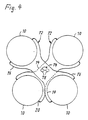
- FIG. 4 illustrates the assembly of four cylindrical sieve compartments 10 arranged in a square in a plan sifter.
- the diagonally opposite sieve compartments are each connected to one another by a common yoke 72.
- Each yoke 72 has a wide central web 74 and forms two semicircular forks 76 at its opposite ends, each of which firmly holds one of the two half-shells 18 of the housing of the associated sieve compartment 10.
- the central webs 74 of the yokes 72 are provided with central bores 78, in which two are at 180 ° offset crank pins of a drive crankshaft, not shown, are mounted.
- the two yokes 72 with the associated sieve compartments 10 are driven in such a way that they revolve around a stationary common center of gravity. Balancing by counterweights is not necessary with this construction.
- the cylindrical shape of the sieve compartments 10 enables a broad and correspondingly stable design of the central webs 74 of the yokes 72.
Priority Applications (1)
| Application Number | Priority Date | Filing Date | Title |
|---|---|---|---|
| EP92118340A EP0536803B1 (fr) | 1988-01-30 | 1989-01-30 | Nettoyeur pour tamis, en particulier pour plansichter |
Applications Claiming Priority (2)
| Application Number | Priority Date | Filing Date | Title |
|---|---|---|---|
| DE3802799 | 1988-01-30 | ||
| DE3802799A DE3802799A1 (de) | 1988-01-30 | 1988-01-30 | Plansichter |
Related Child Applications (2)
| Application Number | Title | Priority Date | Filing Date |
|---|---|---|---|
| EP92118340.6 Division-Into | 1989-01-30 | ||
| EP92118340A Division EP0536803B1 (fr) | 1988-01-30 | 1989-01-30 | Nettoyeur pour tamis, en particulier pour plansichter |
Publications (2)
| Publication Number | Publication Date |
|---|---|
| EP0330846A2 true EP0330846A2 (fr) | 1989-09-06 |
| EP0330846A3 EP0330846A3 (fr) | 1990-06-27 |
Family
ID=6346328
Family Applications (2)
| Application Number | Title | Priority Date | Filing Date |
|---|---|---|---|
| EP92118340A Expired - Lifetime EP0536803B1 (fr) | 1988-01-30 | 1989-01-30 | Nettoyeur pour tamis, en particulier pour plansichter |
| EP89101573A Withdrawn EP0330846A3 (fr) | 1988-01-30 | 1989-01-30 | Plansichter |
Family Applications Before (1)
| Application Number | Title | Priority Date | Filing Date |
|---|---|---|---|
| EP92118340A Expired - Lifetime EP0536803B1 (fr) | 1988-01-30 | 1989-01-30 | Nettoyeur pour tamis, en particulier pour plansichter |
Country Status (4)
| Country | Link |
|---|---|
| EP (2) | EP0536803B1 (fr) |
| AT (1) | ATE127043T1 (fr) |
| DE (2) | DE8816420U1 (fr) |
| ES (1) | ES2078624T3 (fr) |
Cited By (8)
| Publication number | Priority date | Publication date | Assignee | Title |
|---|---|---|---|---|
| WO1991004802A1 (fr) * | 1989-10-04 | 1991-04-18 | Rueter Reinhard | Cribleur et procede de criblage de controle |
| WO1993016815A1 (fr) * | 1992-02-29 | 1993-09-02 | Bühler AG | Dispositif pour tamis plan |
| DE19706601C1 (de) * | 1997-02-20 | 1998-11-12 | Buehler Ag | Siebrahmen für Plansichter und Verfahren zu dessen Herstellung |
| US6260710B1 (en) | 1996-08-20 | 2001-07-17 | Buhler Ag | Flat sifter |
| EP1224984A2 (fr) * | 2001-01-19 | 2002-07-24 | Bühler AG | Tamis |
| RU2687727C2 (ru) * | 2014-10-24 | 2019-05-15 | Бюлер Аг | Ситоочиститель, узел грохота и способ |
| CN112938019A (zh) * | 2021-04-06 | 2021-06-11 | 江西诺泰生物科技有限公司 | 一种固体饮料包装机可拆卸式投料口除杂装置 |
| EP4197655A1 (fr) | 2021-12-20 | 2023-06-21 | Bühler AG | Tamis et cadre présentant une meilleure connectabilité |
Families Citing this family (5)
| Publication number | Priority date | Publication date | Assignee | Title |
|---|---|---|---|---|
| DE59707513D1 (de) * | 1997-11-29 | 2002-07-18 | Buehler Ag | Siebreiniger für Plansichter |
| DE19825617A1 (de) * | 1998-06-08 | 1999-12-09 | Filip Gmbh Muellereibuersten | Vorrichtung zur Siebrahmen- und Bodenreinigung eines Siebkastens |
| EP1078697B1 (fr) | 1999-08-18 | 2003-10-22 | ALLGAIER WERKE GmbH | Fond de tamis pour tamis circulaire |
| EP2465616B1 (fr) | 2010-12-15 | 2013-11-06 | Sefar AG | Nettoyeur de tamis pour séparateur plan |
| KR101571955B1 (ko) * | 2014-01-27 | 2015-11-25 | 장상국 | 수평 및 상하 진동을 하는 체질용 곡물 선별장치 |
Citations (9)
| Publication number | Priority date | Publication date | Assignee | Title |
|---|---|---|---|---|
| DE388500C (de) * | 1922-11-01 | 1924-01-19 | Masch Fabrk Und Muehlenbauanst | Freischwingender Vierfachplansichter |
| US2086199A (en) * | 1936-04-10 | 1937-07-06 | Gump B F Co | Cloth cleaner |
| FR892887A (fr) * | 1943-03-26 | 1944-05-23 | Appareil de tamisage | |
| GB927469A (en) * | 1959-09-16 | 1963-05-29 | Buehler Ag Geb | Improvements in or relating to plansifters |
| CH450125A (de) * | 1965-12-08 | 1968-01-15 | Union Seidengaze Gmbh | Siebreiniger |
| GB1134640A (en) * | 1965-01-21 | 1968-11-27 | Southwestern Eng Co | Self-cleaning vibratory separators |
| US3422955A (en) * | 1966-04-11 | 1969-01-21 | Smico Inc | Superimposed gyratory sifters |
| SU1125068A1 (ru) * | 1983-07-19 | 1984-11-23 | Lejkin Yakov | Ситова рама дл рассевов с круговым поступательным движением |
| DE8631814U1 (fr) * | 1986-11-27 | 1987-02-19 | Filip, Martin, 4830 Guetersloh, De |
Family Cites Families (3)
| Publication number | Priority date | Publication date | Assignee | Title |
|---|---|---|---|---|
| FR1282737A (fr) * | 1960-12-17 | 1962-01-27 | Socam Sa | Dispositif pour le dégommage des fonds d'appareils de tamisage |
| US3422995A (en) * | 1967-11-13 | 1969-01-21 | Apaw Sa | Portioning and dispensing device including adjustment means to vary the volume of the proportions |
| US4288320A (en) * | 1980-05-05 | 1981-09-08 | Litton Systems, Inc. | Vibrating screen with screen deck unclogging mechanism |
-
1988
- 1988-01-30 DE DE8816420U patent/DE8816420U1/de not_active Expired
- 1988-01-30 DE DE3802799A patent/DE3802799A1/de active Granted
-
1989
- 1989-01-30 ES ES92118340T patent/ES2078624T3/es not_active Expired - Lifetime
- 1989-01-30 EP EP92118340A patent/EP0536803B1/fr not_active Expired - Lifetime
- 1989-01-30 AT AT92118340T patent/ATE127043T1/de not_active IP Right Cessation
- 1989-01-30 EP EP89101573A patent/EP0330846A3/fr not_active Withdrawn
Patent Citations (9)
| Publication number | Priority date | Publication date | Assignee | Title |
|---|---|---|---|---|
| DE388500C (de) * | 1922-11-01 | 1924-01-19 | Masch Fabrk Und Muehlenbauanst | Freischwingender Vierfachplansichter |
| US2086199A (en) * | 1936-04-10 | 1937-07-06 | Gump B F Co | Cloth cleaner |
| FR892887A (fr) * | 1943-03-26 | 1944-05-23 | Appareil de tamisage | |
| GB927469A (en) * | 1959-09-16 | 1963-05-29 | Buehler Ag Geb | Improvements in or relating to plansifters |
| GB1134640A (en) * | 1965-01-21 | 1968-11-27 | Southwestern Eng Co | Self-cleaning vibratory separators |
| CH450125A (de) * | 1965-12-08 | 1968-01-15 | Union Seidengaze Gmbh | Siebreiniger |
| US3422955A (en) * | 1966-04-11 | 1969-01-21 | Smico Inc | Superimposed gyratory sifters |
| SU1125068A1 (ru) * | 1983-07-19 | 1984-11-23 | Lejkin Yakov | Ситова рама дл рассевов с круговым поступательным движением |
| DE8631814U1 (fr) * | 1986-11-27 | 1987-02-19 | Filip, Martin, 4830 Guetersloh, De |
Non-Patent Citations (1)
| Title |
|---|
| SOVIET UNION INVENTIONS ILLUSTRATED, Woche 8522, 11. Juli 1985, Sektion P, Zusammenfassung Nr. 85-133952/22, Derwent Publications Ltd, London, GB; & SU-A-1125 068 (LEIKIN YAI) 23-11-1984 * |
Cited By (13)
| Publication number | Priority date | Publication date | Assignee | Title |
|---|---|---|---|---|
| WO1991004802A1 (fr) * | 1989-10-04 | 1991-04-18 | Rueter Reinhard | Cribleur et procede de criblage de controle |
| WO1993016815A1 (fr) * | 1992-02-29 | 1993-09-02 | Bühler AG | Dispositif pour tamis plan |
| EP0694341A1 (fr) | 1992-02-29 | 1996-01-31 | Bühler Ag | Dispositif pour le nettoyage des tamis |
| US5538139A (en) * | 1992-02-29 | 1996-07-23 | Buehler Ag | Arrangement for a plansifter |
| US6260710B1 (en) | 1996-08-20 | 2001-07-17 | Buhler Ag | Flat sifter |
| US6202857B1 (en) | 1997-02-20 | 2001-03-20 | Buhler Ag | Frame for flat sifter and process for producing the same |
| DE19706601C1 (de) * | 1997-02-20 | 1998-11-12 | Buehler Ag | Siebrahmen für Plansichter und Verfahren zu dessen Herstellung |
| EP1224984A2 (fr) * | 2001-01-19 | 2002-07-24 | Bühler AG | Tamis |
| EP1224984A3 (fr) * | 2001-01-19 | 2002-11-27 | Bühler AG | Tamis |
| RU2687727C2 (ru) * | 2014-10-24 | 2019-05-15 | Бюлер Аг | Ситоочиститель, узел грохота и способ |
| CN112938019A (zh) * | 2021-04-06 | 2021-06-11 | 江西诺泰生物科技有限公司 | 一种固体饮料包装机可拆卸式投料口除杂装置 |
| EP4197655A1 (fr) | 2021-12-20 | 2023-06-21 | Bühler AG | Tamis et cadre présentant une meilleure connectabilité |
| WO2023117137A1 (fr) | 2021-12-20 | 2023-06-29 | Bühler AG | Tamis et cadre à connectabilité améliorée |
Also Published As
| Publication number | Publication date |
|---|---|
| ES2078624T3 (es) | 1995-12-16 |
| EP0536803B1 (fr) | 1995-08-30 |
| DE8816420U1 (fr) | 1989-08-10 |
| EP0536803A1 (fr) | 1993-04-14 |
| DE3802799A1 (de) | 1989-08-10 |
| ATE127043T1 (de) | 1995-09-15 |
| EP0330846A3 (fr) | 1990-06-27 |
| DE3802799C2 (fr) | 1989-12-21 |
Similar Documents
| Publication | Publication Date | Title |
|---|---|---|
| EP0694341B1 (fr) | Dispositif pour le nettoyage des tamis | |
| DE3802799C2 (fr) | ||
| DE3114574C2 (fr) | ||
| DE2951291B1 (de) | Siebmaschine | |
| DE19825617A1 (de) | Vorrichtung zur Siebrahmen- und Bodenreinigung eines Siebkastens | |
| DE3741966C2 (fr) | ||
| EP0405477A1 (fr) | Appareil de tamisage | |
| DE1242079B (de) | Siebboden | |
| DE2256307A1 (de) | Plansichter | |
| DE1507741B1 (de) | Selbstreinigendes Sichtersieb fuer Ruettelsichter | |
| WO1999028053A1 (fr) | Nettoyeur de tamis pour crible plat | |
| EP0218575A2 (fr) | Dispositif de tamisage | |
| DE3807843A1 (de) | Vorrichtung zum vermahlen und separieren von korngut | |
| DE2923474C2 (de) | Siebmaschine | |
| DE3018741C2 (fr) | ||
| DE3121947C2 (de) | Rüttelvorrichtung und Anordnung der Rüttelvorrichtung an einem Wärmetauscher | |
| DE4323901C2 (de) | Schwingsieb | |
| DE3326481C1 (de) | Siebmaschine | |
| DE3114573A1 (de) | "vibrationssieb mit selbsttragendem siebmaschendrahtgewebe" | |
| CH637850A5 (en) | Vibrating ball mill | |
| AT389062B (de) | Siebvorrichtung | |
| DE1258713B (de) | Schwingsieb mit in einem Siebkasten eingespanntem, zusammen mit diesem in Schwingungen versetztem Siebbelag und mit einer Abklopfvorrichtung | |
| AT393466B (de) | Vibrationstrennvorrichtung | |
| DE2153710A1 (de) | Abfallseparator für grüne Bohnen | |
| DE1300720B (de) | Vibrations-Arbeitsvorrichtung |
Legal Events
| Date | Code | Title | Description |
|---|---|---|---|
| PUAI | Public reference made under article 153(3) epc to a published international application that has entered the european phase |
Free format text: ORIGINAL CODE: 0009012 |
|
| AK | Designated contracting states |
Kind code of ref document: A2 Designated state(s): AT BE CH DE ES FR GB GR IT LI LU NL SE |
|
| RBV | Designated contracting states (corrected) |
Designated state(s): AT BE CH ES FR GB IT LI SE |
|
| REG | Reference to a national code |
Ref country code: DE Ref legal event code: 8566 |
|
| PUAL | Search report despatched |
Free format text: ORIGINAL CODE: 0009013 |
|
| AK | Designated contracting states |
Kind code of ref document: A3 Designated state(s): AT BE CH ES FR GB IT LI SE |
|
| 17P | Request for examination filed |
Effective date: 19901207 |
|
| 17Q | First examination report despatched |
Effective date: 19911216 |
|
| STAA | Information on the status of an ep patent application or granted ep patent |
Free format text: STATUS: THE APPLICATION IS DEEMED TO BE WITHDRAWN |
|
| 18D | Application deemed to be withdrawn |
Effective date: 19930217 |