EP0330192A2 - Roller shutter for closing openings - Google Patents
Roller shutter for closing openings Download PDFInfo
- Publication number
- EP0330192A2 EP0330192A2 EP19890103139 EP89103139A EP0330192A2 EP 0330192 A2 EP0330192 A2 EP 0330192A2 EP 19890103139 EP19890103139 EP 19890103139 EP 89103139 A EP89103139 A EP 89103139A EP 0330192 A2 EP0330192 A2 EP 0330192A2
- Authority
- EP
- European Patent Office
- Prior art keywords
- roller shutter
- guide
- locking
- guide rail
- pressure plate
- Prior art date
- Legal status (The legal status is an assumption and is not a legal conclusion. Google has not performed a legal analysis and makes no representation as to the accuracy of the status listed.)
- Granted
Links
Images


Classifications
-
- E—FIXED CONSTRUCTIONS
- E06—DOORS, WINDOWS, SHUTTERS, OR ROLLER BLINDS IN GENERAL; LADDERS
- E06B—FIXED OR MOVABLE CLOSURES FOR OPENINGS IN BUILDINGS, VEHICLES, FENCES OR LIKE ENCLOSURES IN GENERAL, e.g. DOORS, WINDOWS, BLINDS, GATES
- E06B9/00—Screening or protective devices for wall or similar openings, with or without operating or securing mechanisms; Closures of similar construction
- E06B9/24—Screens or other constructions affording protection against light, especially against sunshine; Similar screens for privacy or appearance; Slat blinds
- E06B9/26—Lamellar or like blinds, e.g. venetian blinds
- E06B9/28—Lamellar or like blinds, e.g. venetian blinds with horizontal lamellae, e.g. non-liftable
- E06B9/34—Lamellar or like blinds, e.g. venetian blinds with horizontal lamellae, e.g. non-liftable roller-type; Roller shutters with adjustable lamellae
-
- E—FIXED CONSTRUCTIONS
- E06—DOORS, WINDOWS, SHUTTERS, OR ROLLER BLINDS IN GENERAL; LADDERS
- E06B—FIXED OR MOVABLE CLOSURES FOR OPENINGS IN BUILDINGS, VEHICLES, FENCES OR LIKE ENCLOSURES IN GENERAL, e.g. DOORS, WINDOWS, BLINDS, GATES
- E06B9/00—Screening or protective devices for wall or similar openings, with or without operating or securing mechanisms; Closures of similar construction
- E06B9/02—Shutters, movable grilles, or other safety closing devices, e.g. against burglary
- E06B9/08—Roll-type closures
- E06B9/11—Roller shutters
- E06B9/15—Roller shutters with closing members formed of slats or the like
- E06B9/165—Roller shutters with closing members formed of slats or the like with slats disappearing in each other; with slats the distance between which can be altered
-
- E—FIXED CONSTRUCTIONS
- E06—DOORS, WINDOWS, SHUTTERS, OR ROLLER BLINDS IN GENERAL; LADDERS
- E06B—FIXED OR MOVABLE CLOSURES FOR OPENINGS IN BUILDINGS, VEHICLES, FENCES OR LIKE ENCLOSURES IN GENERAL, e.g. DOORS, WINDOWS, BLINDS, GATES
- E06B9/00—Screening or protective devices for wall or similar openings, with or without operating or securing mechanisms; Closures of similar construction
- E06B9/56—Operating, guiding or securing devices or arrangements for roll-type closures; Spring drums; Tape drums; Counterweighting arrangements therefor
- E06B9/80—Safety measures against dropping or unauthorised opening; Braking or immobilising devices; Devices for limiting unrolling
- E06B9/82—Safety measures against dropping or unauthorised opening; Braking or immobilising devices; Devices for limiting unrolling automatic
- E06B9/86—Safety measures against dropping or unauthorised opening; Braking or immobilising devices; Devices for limiting unrolling automatic against unauthorised opening
-
- E—FIXED CONSTRUCTIONS
- E06—DOORS, WINDOWS, SHUTTERS, OR ROLLER BLINDS IN GENERAL; LADDERS
- E06B—FIXED OR MOVABLE CLOSURES FOR OPENINGS IN BUILDINGS, VEHICLES, FENCES OR LIKE ENCLOSURES IN GENERAL, e.g. DOORS, WINDOWS, BLINDS, GATES
- E06B9/00—Screening or protective devices for wall or similar openings, with or without operating or securing mechanisms; Closures of similar construction
- E06B9/02—Shutters, movable grilles, or other safety closing devices, e.g. against burglary
- E06B9/08—Roll-type closures
- E06B9/11—Roller shutters
- E06B9/15—Roller shutters with closing members formed of slats or the like
- E06B2009/1577—Slat end pieces used for guiding shutter
- E06B2009/1583—Slat end pieces used for guiding shutter inserted in slat cavity
-
- E—FIXED CONSTRUCTIONS
- E06—DOORS, WINDOWS, SHUTTERS, OR ROLLER BLINDS IN GENERAL; LADDERS
- E06B—FIXED OR MOVABLE CLOSURES FOR OPENINGS IN BUILDINGS, VEHICLES, FENCES OR LIKE ENCLOSURES IN GENERAL, e.g. DOORS, WINDOWS, BLINDS, GATES
- E06B9/00—Screening or protective devices for wall or similar openings, with or without operating or securing mechanisms; Closures of similar construction
- E06B9/02—Shutters, movable grilles, or other safety closing devices, e.g. against burglary
- E06B9/08—Roll-type closures
- E06B9/11—Roller shutters
- E06B9/15—Roller shutters with closing members formed of slats or the like
- E06B2009/1577—Slat end pieces used for guiding shutter
- E06B2009/1588—Slat end pieces used for guiding shutter inserted in engaging section of adjacent slats
-
- E—FIXED CONSTRUCTIONS
- E06—DOORS, WINDOWS, SHUTTERS, OR ROLLER BLINDS IN GENERAL; LADDERS
- E06B—FIXED OR MOVABLE CLOSURES FOR OPENINGS IN BUILDINGS, VEHICLES, FENCES OR LIKE ENCLOSURES IN GENERAL, e.g. DOORS, WINDOWS, BLINDS, GATES
- E06B9/00—Screening or protective devices for wall or similar openings, with or without operating or securing mechanisms; Closures of similar construction
- E06B9/56—Operating, guiding or securing devices or arrangements for roll-type closures; Spring drums; Tape drums; Counterweighting arrangements therefor
- E06B9/80—Safety measures against dropping or unauthorised opening; Braking or immobilising devices; Devices for limiting unrolling
- E06B2009/801—Locking arrangements
- E06B2009/805—Locking arrangements located on or in the guides
Definitions
- the invention relates to a roller shutter according to the preamble of claim 1.
- roller shutter requires relatively thick roller shutter slats in the construction according to the generic literature reference, so that the articulation axes of the roller shutter slats in the upper and lower area are not aligned with one another but are offset from one another.
- the invention has for its object to provide a roller shutter in which the shutter bars can be made from commercially available roller shutter profile elements, which is burglar-proof in that the roller shutter can no longer be pushed up is and is constructed more simply than the generic roller shutter known.
- the individual roller shutter bars are connected to one another via connectors so that the connecting axes or hinge axes of the roller shutter bars to the front and rear guide bodies are aligned with one another in the vertical position of the roller shutter bars and are not offset with respect to one another. Furthermore, a locking element is switched on at least in one of the guide bodies guided in the associated slide rail, which makes it impossible to move the roller shutter rods from below when the roller shutter rods are raised.
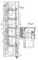
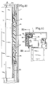
- 1 denotes a guide rail in which a slide rail 4 is formed from the same material.
- the individual roller shutter slats are designated by 2, which are connected to one another and to one another via the axes of rotation 5 and 6 and via the guide bodies 7 and 8 connected to these axes of rotation. From the illustration in the drawings it can be seen that the guide body 8 run in the slide rail 4 and thus also the associated axes of rotation 6, while the guide body 7 freely in space the guide rail 1 and thus also the axes of rotation 5 connected to these guide bodies 7.
- the guide bodies 7 and 8 connect to one another via connectors 22, which contain the axes of rotation 5 and 6 and which also create a bearing seat 23 (FIG. 3), into which the guide bodies 7 insert when the roller shutter bars 2 are placed vertically.
- the guide bodies 7 close, which cannot be seen from the drawing, to the winding shaft (not shown in the drawing), and from this it can be seen that in the illustration according to FIG. 1, when the winding shaft is rotated, the guide body 7 from its first in FIG 1 shown position is guided into the position shown in Fig. 2 and that when all the shutter bars 2 are placed vertically, rolling up the shutter is possible.
- a slide rail 31 is mounted in the guide rail 1 and, viewed in the longitudinal axis of the guide rail 1, can be moved up and down.
- This slide rail 31 carries locking hooks 32 which cooperate with the handlebar 30 and lock this handlebar in the illustration according to FIG. 1. 1, the locking hooks 1 are moved downward, they release the locking with the handlebars 30 and come with their rear side into contact with a sliding skid 35 of the handlebar below and thereby move the handlebars 30 into space of the guide rail 1.
- the links in turn carry a pressure plate 24 which, in the position shown in FIG. 1, abuts approximately on the rear wall 25 of the guide rail 1 and in which in FIG. 2 position shown on the handlebar 30 has been placed on the back of the vertically placed shutter bars 2.
- the movement of the pressure plate 24 from the position shown in FIG. 1 to the position shown in FIG. 2 can be spring-assisted, so that the pressure plate 24 bears securely and firmly against the rear of the roller shutter bars 2.
- the movement of the slide rail 31 is controlled by an unlocking lever 29 which is operated by the roller shutter bars. From the illustration in Fig. 1 it can be seen that with an upward movement, for example by a corresponding rotation of the winding shaft, the top roller shutter rod 2 pivots the unlocking lever 29 counterclockwise. As a result, the unlocking lever 29 controls the slide rail 31 downward, for example via an eccentric control, the locking hooks 32 release the handlebar 30, and the pressure plate 24 can then move in the direction of the slide rail 4 in the guide rail 1.
- a control cam 28 is provided at the lower end of the roller shutter curtain, the upper side of which is designed as an overrun runner 37, so that it strives when lifting the Roller shutter to guide the pressure plate 24 back into the position shown in Fig. 1.
- This movement can be further supported by the fact that, after the pressure plate 24 has moved back, a guide roller 36 arranged on the adjusting cam 28 comes into contact with the front of the pressure plate 24 and the latter is full constantly moved back so that the locking hook 32 can lock the handlebar 30 again.
- Fig. 1 it can also be seen that the lowermost roller shutter bar is fixed and does not tilt like the roller shutter bars 2 arranged above it and that a seal 38 can be provided on the underside of the roller shutter curtain.
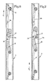
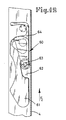
- two guide bodies 8 have been replaced and replaced on the one hand by a locking element 26 and on the other hand by a separate guide body 8a.
- the formation of these two components can be seen more clearly from FIGS. 6 and 7. It can be seen here that the locking element 26 carries a locking claw 27 pivotably seen approximately centrally over its length, namely pivoting about the axis 39. The locking claw 27 is mounted in the locking element 26 with this axis.
- the locking element 26 moves upwards and thereby the guide body 8a pushes the locking claw 27 outwards, which then lockingly comes into contact with the inner wall of the slide rail 4.
- the guide bodies 7 and 8 are made of plastic, as are the connectors 22, in the case of the locking element 26, provision is made for this to be made of metal, as is the guide body 8a adjoining the locking element 26.
- the components 22, 23, 8 and 7 can be used in their function both as a "left-hand roller” and as a “right-hand roller” if the connection to the roller shutter rod 2 is adapted accordingly in the curvature and the shape of the guide body 7 is adapted.
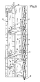
- the slide rail 31a can be seen, which is actuated by the unlocking lever 29.
- the slide rail 31a carries pins 50 which protrude into the space of the guide rail 1.
- These pins 50 engage in a locking body 51 mounted in the guide rail 1, specifically in — as can be clearly seen from FIG. 10 —
- This locking body 51 provided slot holes, which extend obliquely to the longitudinal axis of the locking body 51, so that since the locking body 51 is indirectly or directly fixed in the guide rail 1, when the slide rail 31a moves through the pins 50 of the locking body up and down becomes. This can be seen particularly clearly from FIG. 10.
- the locking body 51 is supported directly or indirectly via compression springs 54 on the guide rail 1, so that these compression springs 54 always strive to guide the locking body 51 into the locking position shown in FIG. 10.
- the actual pressure plate 24 is locked in that, in the position shown in FIG. 10, the upper edge of the locking body 51 engages in a groove 53 in the pressure plate 24.
- the locking body 51 is moved out of this groove 53 by the movement of the slide rail 31a and the consequent forced movement mediated via the pins 50.
- the then inevitable movement of the pressure plate 24 from the position shown in FIG. 8 into the position shown in FIG. 9 takes place in that in each case a spring 55 is provided within the link 30a, which strives to always link the link 30a in the Fig. 9 lead position.
- the links 30a like the links 30 according to the embodiment according to FIGS. 1 to 7, are arranged stationary in the guide rail 1.
- FIG. 12 shows a modified embodiment of the locking device previously described in FIGS. 6 and 7.
- a locking element 60 is provided, which consists of a partial element 61 and a partial element connected to it 64, wherein the two sub-elements 61 and 64 can move against each other.
- the sub-element 64 engages in a recess 62 of the sub-element 61 via an axis 63.
- the axis 63 carries a roller 65.
- the recess 62 is designed so that it widens from bottom to top and the outer diameter of the roller 65 is designed such that this outer diameter is larger than the smallest opening width of the recess 62, but smaller than the largest opening width of the recess 62.
- Fig. 12 it can be seen that if one tries to push the sub-element 61 upwards (in the direction of arrow F2), a wedge-like jamming of the roller 65 takes place, on the one hand between the rear wall of the recess 62 and on the other hand, the inner wall of the slide rail 4. Since, in contrast to the embodiment described with reference to FIGS. 6 and 7, the actual locking element cannot be cut into the guide rail 4, the embodiment described with reference to FIG. 12 works more reliably, but is in the same way burglar-proof like the previously described embodiment.
Abstract
Description
Die Erfindung bezieht sich auf einen Rolladen gemäß dem Oberbegriff des Patentanspruches 1.The invention relates to a roller shutter according to the preamble of
Aus der gattungsbildenden EP B1 59 362 ist ein Rolladen für Öffnungsabschlüsse bekannt, mit dem ein absolut sicheres dichtes Verschließen der Fensteröffnung möglich ist, der aber gleichzeitig eine Licht- und Sonneneintrittsregulierung durch Schrägstellung der Lamellen ermöglicht und der schließlich aufgrund seiner Konstruktion, unabhängig in welcher Stellung sich die Rollädenstäbe befinden, einbruchsicher ist. Außerdem soll durch den neuen Rolladen die Schall- und Wärmeisolierung verbessert werden.From the generic EP B1 59 362, a roller shutter for opening closures is known, with which an absolutely secure, tight closing of the window opening is possible, but which at the same time enables light and sun entry regulation by inclining the slats and, finally, due to its construction, regardless of the position the roller shutter bars are burglar-proof. In addition, the new roller shutters are intended to improve sound and heat insulation.
Der bekannte Rolladen benötigt bei der Konstruktion gemäß der gattungsbildenden Literaturstelle relativ dicke Rolladenstäbe, so daß die Anlenkachsen der Rolladenstäbe im oberen und unteren Bereich nicht miteinander fluchten, sondern gegeneinander versetzt sind.The known roller shutter requires relatively thick roller shutter slats in the construction according to the generic literature reference, so that the articulation axes of the roller shutter slats in the upper and lower area are not aligned with one another but are offset from one another.
Der Erfindung liegt die Aufgabe zugrunde, einen Rolladen zu schaffen, bei dem die Rolladenstäbe aus handelsüblichen Rolladenprofilelementen gefertigt werden können, der einbruchsicher ist dadurch, daß ein Hochschieben des Rolladens nicht mehr möglich ist und der einfacher aufgebaut ist, als der gattungsbildende bekannte Rolladen.The invention has for its object to provide a roller shutter in which the shutter bars can be made from commercially available roller shutter profile elements, which is burglar-proof in that the roller shutter can no longer be pushed up is and is constructed more simply than the generic roller shutter known.
Diese der Erfindung zugrundeliegende Aufgabe wird durch die Lehre des Hauptanspruches gelöst.This object on which the invention is based is achieved by the teaching of the main claim.
Vorteilhafte Ausgestaltungen sind in den Unteransprüchen erläutert.Advantageous configurations are explained in the subclaims.
Mit anderen Worten ausgedrückt, wird vorgeschlagen, daß die einzelnen Rolladenstäbe über Verbinder miteinander so verbunden sind, daß die Anschlußachsen oder Gelenkachsen der Rolladenstäbe an die vorderen und hinteren Führungskörper in der Vertikalstellung der Rolladenstäbe miteinander fluchten und nicht gegeneinander versetzt sind. Weiterhin ist zumindest in einem der in der zugehörigen Gleitschiene geführten Führungskörper ein Riegelelement eingeschaltet, daß bei Anheben der Rolladenstäbe von unten her ein Bewegen der Rolladenstäbe unmöglich macht.In other words, it is proposed that the individual roller shutter bars are connected to one another via connectors so that the connecting axes or hinge axes of the roller shutter bars to the front and rear guide bodies are aligned with one another in the vertical position of the roller shutter bars and are not offset with respect to one another. Furthermore, a locking element is switched on at least in one of the guide bodies guided in the associated slide rail, which makes it impossible to move the roller shutter rods from below when the roller shutter rods are raised.
Vorteilhafte Ausgestaltungen sind in den Unteransprüchen erläutert.Advantageous configurations are explained in the subclaims.
Ausführungsbeispiele sogenannter "Linksroller" gemäß der Erfindung werden nachfolgend anhand der Zeichnungen beschrieben.Exemplary embodiments of so-called "left-hand rollers" according to the invention are described below with reference to the drawings.
Die Zeichnungen zeigen dabei in
- Fig. 1 in einer Schnittdarstellung eine Seitenansicht auf einen Rolladenabschnitt bei horizontal eingestellten Rolladenstäben,
- Fig. 2 eine Darstellung bei vertikal eingestellten Rolladenstäben,
- Fig. 3 in größerem Maßstab zur Verdeutlichung unter Wegbruch einiger Teile die Verbindung der Rolladenstäbe miteinander,
- Fig. 4 eine Darstellung gemäß Fig. 3, wobei aber in die Führungskörper ein Riegelelement eingeschaltet ist,
- Fig. 5 eine Schnittdarstellung gemäß der Linie 5 - 5 in Fig. 1 durch die Führungsschiene zur Aufnahme der Rolladenstabführungen,
- Fig. 6 in größerem Maßstab das Riegelelement in seiner unwirksamen Lage,
- Fig. 7 das Riegelelement im Riegelzustand,
- Fig. 8 eine Fig. 1 entsprechende abgeänderte Ausführungsform,
- Fig. 9 eine Fig. 2 entsprechende Darstellung der Ausführungsform nach Fig. 8,
- Fig. 10 eine Schnittdarstellung gemäß der Linie 10 - 10 in Fig. 11,
- Fig. 11 einen Schnitt gemäß der Linie 11 - 11 durch Fig. 8 und
- Fig. 12 eine abgeänderte Ausführungsform der Verriegelungsvorrichtung.
- 1 is a sectional side view of a roller shutter section with horizontally adjusted shutter bars,
- 2 is an illustration with vertically adjusted roller shutter bars,
- 3 on a larger scale to illustrate the connection of the roller shutter bars with each other,
- 4 shows a representation according to FIG. 3, but with a locking element being switched on in the guide body,
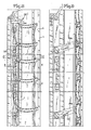
- 5 shows a sectional view along the line 5 - 5 in FIG. 1 through the guide rail for receiving the roller shutter rod guides,
- 6 on a larger scale the locking element in its inactive position,
- 7 the locking element in the locking state,
- 8 shows a modified embodiment corresponding to FIG. 1,
- 9 shows a representation corresponding to FIG. 2 of the embodiment according to FIG. 8,
- 10 is a sectional view taken along the line 10-10 in Fig. 11,
- 11 shows a section along the line 11-11 through FIGS. 8 and
- Fig. 12 shows a modified embodiment of the locking device.
In den Zeichnungen gemäß Fig. 1 - 7 (siehe besonders Fig. 5) ist mit 1 eine Führungsschiene bezeichnet, in der eine Gleitschiene 4 materialeinheitlich ausgeformt ist. Mit 2 sind die einzelnen Rolladenstäbe bezeichnet, die untereinander und miteinander über die Drehachsen 5 und 6 und über die mit diesen Drehachsen verbundenen Führungskörper 7 und 8 verbunden sind. Aus der Darstellung in den Zeichnungen ist erkennbar, daß die Führungskörper 8 in der Gleitschiene 4 laufen und damit auch die zugehörigen Drehachsen 6, während die Führungskörper 7 frei im Raum der Führungsschiene 1 stehen und damit auch die mit diesen Führungskörpern 7 verbundenen Drehachsen 5.In the drawings according to FIGS. 1-7 (see particularly FIG. 5), 1 denotes a guide rail in which a
Die Führungskörper 7 und 8 schließen aneinander über Verbinder 22 an, die die Drehachsen 5 und 6 beinhalten und die außerdem eine Lageraufnahme 23 (Fig. 3) schaffen, in die sich die Führungskörper 7 einlegen, wenn die Rolladenstäbe 2 vertikal gestellt sind.The
Die Führungskörper 7 schließen, was aus der Zeichnung nicht zu erkennen ist, an die in der Zeichnung nicht dargestellte Wickelwelle an, und hieraus wird erkennbar, daß bei der Darstellung gemäß Fig. 1 bei einem Drehen der Wickelwelle zuerst der Führungskörper 7 aus seiner in Fig. 1 dargestellten Stellung in die in Fig. 2 dargestellte Stellung geführt wird und daß, wenn derart alle Rolladenstäbe 2 vertikal gestellt sind, ein Aufrollen des Rolladens möglich ist.The
In der Führungsschiene 1 ist eine Gleitschiene 31 gelagert, die in Längsachse der Führungsschiene 1 gesehen auf und ab bewegt werden kann. Diese Gleitschiene 31 trägt Riegelhaken 32, die mit Lenker 30 zusammenarbeiten und bei der Darstellung gemäß Fig. 1 diese Lenker verriegeln. Werden nunmehr bei der Darstellung gemäß Fig. 1 die Riegelhaken 1 nach unten bewegt, geben sie die Verriegelung mit den Lenkern 30 frei und kommen mit ihrer Rückseite mit einer Aufgleitkufe 35 des sich darunter befindlichen Lenkers in Kontakt und bewegen dadurch die Lenker 30 in den Raum der Führungsschiene 1. Die Lenker ihrerseits tragen eine Druckplatte 24, die bei der in Fig. 1 dargestellten Stellung etwa an der Rückwand 25 der Führungsschiene 1 anliegt und bei der in Fig. 2 dargestellten Stellung über die Lenker 30 an die Rückseite der vertikal gestellten Rolladenstäbe 2 gelegt worden ist. Hierbei kann die Bewegung der Druckplatte 24 aus der in Fig. 1 dargestellten Stellung in die in Fig. 2 dargestellte Stellung federunterstützt sein, so daß ein sicheres und festes Anliegen der Druckplatte 24 an der Rückseite der Rolladenstäbe 2 erfolgt.A
Die Bewegung der Gleitschiene 31 wird durch einen Entriegelungshebel 29 gesteuert, der von den Rolladenstäben betätigt wird. Aus der Darstellung in Fig. 1 ist ersichtlich, daß bei einer Hochbewegung, beispielsweise durch entsprechende Drehung der Wickelwelle, der oberste Rolladenstab 2 den Entriegelungshebel 29 entgegen dem Uhrzeigersinn nach oben schwenkt. Hierdurch steuert der Entriegelungshebel 29 beispielsweise über eine Exzentersteuerung die Gleitschiene 31 nach unten, die Riegelhaken 32 geben die Lenker 30 frei, und so kann sich dann die Druckplatte 24 in Richtung auf die Gleitschiene 4 in der Führungsschiene 1 bewegen.The movement of the
Um die Druckplatte aus der in Fig. 2 dargestellten Stellung wieder in die in Fig. 1 dargestellte Stellung zurückzuführen, ist am unteren Ende des Rolladenpanzers ein Stellnocken 28 vorgesehen, dessen Oberseite als Auflaufkufe 37 ausgebildet ist, so daß er bestrebt ist, bei Anheben des Rolladens die Druckplatte 24 wieder zurück in die in Fig. 1 dargestellte Stellung zu führen. Diese Bewegung kann noch dadurch unterstützt werden, daß dann, nach Zurückbewegung der Druckplatte 24, eine an dem Stellnocken 28 angeordnete Führungsrolle 36 mit der Vorderseite der Druckplatte 24 in Kontakt kommt und diese voll ständig zurückbewegt, so daß dadurch die Riegelhaken 32 die Lenker 30 wieder verriegeln können.In order to return the pressure plate from the position shown in FIG. 2 back to the position shown in FIG. 1, a
Aus Fig. 1 ist weiterhin ersichtlich, daß der unterste Rolladenstab feststeht und nicht kippt, wie die darüber angeordneten Rolladenstäbe 2 und daß an der Unterseite des Rolladenpanzers eine Dichtung 38 vorgesehen sein kann.From Fig. 1 it can also be seen that the lowermost roller shutter bar is fixed and does not tilt like the
Aus der Darstellung in Fig. 3 ist die Verbindung der Rolladenstäbe 2 mit den ihnen zugeordneten Führungskörpern 7 und 8 über die Drehachsen 5 und 6 deutlicher erkennbar, wobei auch sehr deutlich die Lageraufnahme 23 erkennbar ist. Hieraus ist weiterhin erkennbar, daß bei Hochziehen des Rolladenpanzers nunmehr die Drehachsen 5 und 6 miteinander auf einer Vertikallinie fluchten.The connection of the
Bei der Ausführungsform gemäß Fig. 4 sind zwei Führungskörper 8 ausgewechselt und einerseits durch ein Riegelelement 26 und andererseits durch einen gesonderten Führungskörper 8a ersetzt. Die Ausbildung dieser beiden Bauteile geht deutlicher aus Fig. 6 und 7 hervor. Hier ist erkennbar, daß das Riegelelement 26 etwa mittig über seine Länge gesehen schwenkbar eine Riegelklaue 27 trägt, und zwar schwenkbar um die Achse 39. Mit dieser Achse ist die Riegelklaue 27 in dem Riegelelement 26 gelagert.In the embodiment according to FIG. 4, two
An die Riegelklaue 27 schließt über die Drehachse 6a der Führungskörper 8a an, so daß bei einem Zug am Rolladen in Richtung des Pfeiles F₁ von oben her die Riegelklaue in die in Fig. 6 dargestellte Stellung eingeschwenkt wird, d.h. nicht mit den Wandungen der Gleitschiene 4 in Kontakt kommen kann.At the
Wird nunmehr versucht, den Rolladenpanzer von unten her hoch zu drücken und also ein Druck in Richtung des Pfeiles F₂ auf den Rolladenpanzer von unten her ausgeübt, schiebt sich das Riegelelement 26 nach oben und hierdurch drückt der Führungskörper 8a die Riegelklaue 27 nach außen, die dann verriegelnd mit der Innenwand der Gleitschiene 4 in Kontakt kommt. Während normalerweise die Führungskörper 7 und 8 aus Kunststoff bestehen, ebenso wie die Verbinder 22, ist im Fall des Riegelelementes 26 vorgesehen, dieses aus Metall herzustellen, ebenso wie den an das Riegelelement 26 anschließenden Führungskörper 8a.If attempts are now made to push the roller shutter armor up from below and thus exert a pressure in the direction of arrow F₂ on the roller shutter armor from below, the
Die Bauteile 22, 23, 8 und 7 können in ihrer Funktion sowohl als "Linksroller" als auch als "Rechtsroller" eingesetzt werden, wenn der Anschluß an den Rolladenstab 2 in der Wölbung entsprechend angepaßt wird und der Führungskörper 7 in seiner Form angepaßt ist.The
Bei der Ausführungsform gemäß den Fig. 8 bis 11 ist eine leicht abgewandelte Verriegelungsvorrichtung für die Druckplatte 24 vorgesehen, wobei alle mit der vorhergehenden Ausführungsform gleichen Teile die gleichen Bezugszeichen tragen.In the embodiment according to FIGS. 8 to 11, a slightly modified locking device for the
In Fig. 8 bis 11 ist die Gleitschiene 31a erkennbar, die von dem Entriegelungshebel 29 betätigt wird. Anstelle der Riegelhaken 32 gemäß der Ausführungsform nach Fig. 1 bis 7 trägt die Gleitschiene 31a Zapfen 50, die in den Raum der Führungsschiene 1 vorstehen. Diese Zapfen 50 greifen dabei in einen in der Führungsschiene 1 gelagerten Riegelkörper 51 ein, und zwar in - wie aus Fig. 10 deutlich zu ersehen - diesem Riegelkörper 51 vorgesehene Langlochschlitze, die sich schräg zur Längsachse des Riegelkörpers 51 erstrecken, so daß, da der Riegelkörper 51 in der Führungsschiene 1 mittelbar oder unmittelbar ortsfest angeordnet ist, bei einer Bewegung der Gleitschiene 31a durch die Zapfen 50 der Riegelkörper auf- und abbewegt wird. Dies wird besonders deutlich aus Fig. 10 erkennbar. Der Riegelkörper 51 stützt sich dabei über Druckfedern 54 an der Führungsschiene 1 mittelbar oder unmittelbar ab, so daß diese Druckfedern 54 immer bestrebt sind, den Riegelkörper 51 in die in Fig. 10 dargestellte Verriegelungsstellung zu führen. Die Verriegelung der eigentlichen Druckplatte 24 erfolgt dadurch, daß in der in Fig. 10 dargestellten Stellung die Oberkante des Riegelkörpers 51 in eine Nut 53 der Druckplatte 24 eingreift. Durch die Bewegung der Gleitschiene 31a und die dadurch bedingte Zwangsbewegung vermittelt über die Zapfen 50 wird der Riegelkörper 51 aus dieser Nut 53 herausbewegt. Die dann zwangsläufig erfolgende Bewegung der Druckplatte 24 aus der in Fig. 8 dargestellten Stellung in die in Fig. 9 dargestellte Stellung erfolgt dadurch, daß innerhalb der Lenker 30a jeweils eine Feder 55 vorgesehen ist, die bestrebt ist, stets die Lenker 30a in die in Fig. 9 dargestellte Stellung zu führen. Die Lenker 30a sind dabei ebenso wie die Lenker 30 gemäß der Ausführungsform nach Fig. 1 bis 7 ortsfest in der Führungsschiene 1 angeordnet.8 to 11, the
In Fig. 12 ist eine abgeänderte Ausführungsform der vorher in den Fig. 6 und 7 beschriebenen Verriegelungsvorrichtung dargestellt. Hierbei wird ein Riegelelement 60 vorgesehen, das aus einem Teilelement 61 besteht und einem damit verbundenen Teilelement 64, wobei sich die beiden Teilelemente 61 und 64 gegeneinander bewegen können. Das Teilelement 64 greift über eine Achse 63 in eine Ausnehmung 62 des Teilelementes 61 ein. Die Achse 63 trägt eine Rolle 65.FIG. 12 shows a modified embodiment of the locking device previously described in FIGS. 6 and 7. In this case, a locking
Die Ausnehmung 62 ist so gestaltet, daß sie sich von unten nach oben erweitert und der Außendurchmesser der Rolle 65 ist so gestaltet, daß dieser Außendurchmesser größer als die kleinste Öffnungsweite der Ausnehmung 62 ist, aber kleiner als die größte Öffnungsweite der Ausnehmung 62. Insbesondere beim Betrachten der Fig. 12 wird dabei erkennbar, daß dann, wenn man bestrebt ist, das Teilelement 61 nach oben zu schieben (in Richtung des Pfeiles F₂), ein keilartiges Verklemmen der Rolle 65 erfolgt, und zwar einerseits zwischen der Rückwandung der Ausnehmung 62 und andererseits der Innenwandung der Gleitschiene 4. Da im Gegensatz zu der anhand von Fig. 6 und 7 beschriebenen Ausführungsform kein Einschneiden des eigentlichen Riegelelementes in die Führungsschiene 4 erfolgen kann, arbeitet die anhand von Fig. 12 vorstehend beschriebene Ausführungsform sicherer, aber ist in gleicher Weise einbruchsicher wie die vorher beschriebene Ausführungsform.The
Anstelle einer nur einseitig vorgesehenen Ausnehmung 62 ist es selbstverständlich auch möglich, ein Teilelement zu schaffen, das beiderseits mit Ausnehmung versehen ist, wobei dann das damit zusammenarbeitende Teilelement mit zwei Achsen in entsprechende Ausnehmungen eingreift.Instead of a
Claims (14)
daß die Führungskörper (7) an der oberen Drehachse (5) der Rolladenstäbe (2) anschließen und zur Wickelwelle führen, daß jeder Rolladenstab (2) endseitig fest einen Verbinder (22) aufweist, der einen Endes die Drehachse (5) trägt und anderen Endes die Drehachse (6) aufweist, an der der in der Gleitschiene (4) geführte Führungskörper (8) anschließt,
daß der Verbinder (22) im Bereich der von ihm getragenen Drehachse (6) in Längsachse des Rolladenstabes (2) in Richtung auf die Gleitschiene (4) vom Rolladenstab (2) aus vorspringt und eine Lageraufnahme (23) für den Führungskörper (7) schafft (Fig. 1, 2 und 4).1. Roller shutters for opening closures with guide rails (1) arranged in the area of each of the two vertical opening sides for receiving pressure-tight and articulated guide bodies (7, 8) running in two rows, the length of which corresponds to the height of the roller shutter bars (2) and on which the Roller shutter slats (2) are articulated but rotatably but rotatably in the longitudinal direction of the bar relative to the guide bodies (7, 8) via two parallel axes of rotation (5, 6) and the guide bodies (8) are exclusively mounted on a guide rail (4) that is fixed in the guide rail (1) and are guided so that they can move, while the guide bodies (7) can be moved up and down in the space of the guide rail (1) and can be adjusted transversely to the longitudinal axis of the guide rail (1), characterized in that
that the guide bodies (7) connect to the upper axis of rotation (5) of the roller shutter bars (2) and lead to the winding shaft, that each roller shutter bar (2) has a connector (22) at one end which carries the axis of rotation (5) at one end and others End has the axis of rotation (6) to which the guide body (8) guided in the slide rail (4) connects,
that the connector (22) projects in the area of the axis of rotation (6) carried by it in the longitudinal axis of the roller shutter rod (2) in the direction of the slide rail (4) from the roller shutter rod (2) and a bearing holder (23) for the Guide body (7) creates (Fig. 1, 2 and 4).
Priority Applications (1)
| Application Number | Priority Date | Filing Date | Title |
|---|---|---|---|
| AT89103139T ATE74397T1 (en) | 1988-02-25 | 1989-02-23 | ROLLER SHUTTERS FOR OPENING CLOSURES. |
Applications Claiming Priority (4)
| Application Number | Priority Date | Filing Date | Title |
|---|---|---|---|
| DE3805834 | 1988-02-25 | ||
| DE3805834 | 1988-02-25 | ||
| DE3809058 | 1988-03-18 | ||
| DE3809058A DE3809058A1 (en) | 1988-02-25 | 1988-03-18 | ROLLER SHUTTER FOR OPENING CLOSES |
Publications (3)
| Publication Number | Publication Date |
|---|---|
| EP0330192A2 true EP0330192A2 (en) | 1989-08-30 |
| EP0330192A3 EP0330192A3 (en) | 1990-02-28 |
| EP0330192B1 EP0330192B1 (en) | 1992-04-01 |
Family
ID=25865162
Family Applications (1)
| Application Number | Title | Priority Date | Filing Date |
|---|---|---|---|
| EP89103139A Expired - Lifetime EP0330192B1 (en) | 1988-02-25 | 1989-02-23 | Roller shutter for closing openings |
Country Status (3)
| Country | Link |
|---|---|
| EP (1) | EP0330192B1 (en) |
| DE (2) | DE3809058A1 (en) |
| ES (1) | ES2030543T3 (en) |
Cited By (16)
| Publication number | Priority date | Publication date | Assignee | Title |
|---|---|---|---|---|
| EP0382172A2 (en) * | 1989-02-07 | 1990-08-16 | Günther Erber | Louvered roller shutter |
| EP0623732A2 (en) * | 1993-05-04 | 1994-11-09 | E. KINDT AG, vormals Hans Kiefer AG | Safety device for venetian blinds or roller blinds |
| WO1995014152A1 (en) * | 1993-11-17 | 1995-05-26 | Andreas Erber | Louvrable roller blind |
| EP0667441A1 (en) * | 1994-02-15 | 1995-08-16 | Sui Kuo Cheng | An iron rolling door |
| WO1998037299A2 (en) * | 1997-02-20 | 1998-08-27 | Miller James V | Rolling protective shutters |
| US5887636A (en) * | 1996-05-02 | 1999-03-30 | Neukam; Helmut | Venetian blind |
| US6095224A (en) * | 1998-01-16 | 2000-08-01 | Miller; James V. | Shutter tracks for rolling protective shutters |
| ES2162571A1 (en) * | 1999-07-23 | 2001-12-16 | Barros Alberto Alemany | Venetian blind with moving blades. |
| US6422289B1 (en) | 1997-02-20 | 2002-07-23 | James V. Miller | Deployment control for rolling protective shutters |
| EP1130212A3 (en) * | 2000-03-03 | 2003-07-09 | Günther Erber | Slat insert for roller shutter and other profiles |
| CN102493748A (en) * | 2011-12-19 | 2012-06-13 | 湖南湘联节能科技股份有限公司 | Roller shutter with turnover curtain cloth |
| DE102012007141A1 (en) | 2012-04-10 | 2013-10-10 | Bernhard Spindler | Venetian blinds |
| CN103953273A (en) * | 2014-05-27 | 2014-07-30 | 常州天经新型建材有限公司 | Novel dimmable shutter |
| CN104358508A (en) * | 2014-11-07 | 2015-02-18 | 常州天经新型建材有限公司 | Novel light-adjustable blind window |
| CN105455835A (en) * | 2014-09-03 | 2016-04-06 | 上海联影医疗科技有限公司 | Roller shutter cover plate moving structure |
| CN106089004A (en) * | 2016-08-22 | 2016-11-09 | 张学录 | A kind of electric up-down curtain |
Families Citing this family (6)
| Publication number | Priority date | Publication date | Assignee | Title |
|---|---|---|---|---|
| AT401799B (en) * | 1993-01-27 | 1996-11-25 | Erber Siegfried | Venetian-blind-type roller shutter |
| ES2196936B1 (en) * | 2000-10-27 | 2005-03-01 | Ramon Casals Artigas | POSITIONING SYSTEM OF OREINTABLE LAMPS IN ROLLING BLINDS. |
| DE102005037775B4 (en) * | 2005-08-10 | 2012-11-08 | Roma Kg | Venetian blind |
| DE102005037756B4 (en) * | 2005-08-10 | 2013-07-11 | Roma Kg | roller shutter |
| ES2325010B1 (en) * | 2007-04-13 | 2010-06-01 | Albert Alemany Barros | "ROLLABLE PERSIAN WITH MOBILE LAMPS". |
| IT1399142B1 (en) * | 2010-04-02 | 2013-04-05 | Filippo De | FOLDABLE WITH ANTI-BURNING SYSTEM |
Citations (3)
| Publication number | Priority date | Publication date | Assignee | Title |
|---|---|---|---|---|
| EP0056650A2 (en) * | 1981-01-20 | 1982-07-28 | Hüppe GmbH | Roller shutter |
| EP0059362A1 (en) * | 1981-03-04 | 1982-09-08 | Jan Hofman | Roller shutter for the closure of openings |
| EP0189091A2 (en) * | 1985-01-19 | 1986-07-30 | Helmut Rathmann | Roller shutter with louvre |
-
1988
- 1988-03-18 DE DE3809058A patent/DE3809058A1/en not_active Withdrawn
-
1989
- 1989-02-23 DE DE8989103139T patent/DE58901061D1/en not_active Expired - Fee Related
- 1989-02-23 EP EP89103139A patent/EP0330192B1/en not_active Expired - Lifetime
- 1989-02-23 ES ES198989103139T patent/ES2030543T3/en not_active Expired - Lifetime
Patent Citations (3)
| Publication number | Priority date | Publication date | Assignee | Title |
|---|---|---|---|---|
| EP0056650A2 (en) * | 1981-01-20 | 1982-07-28 | Hüppe GmbH | Roller shutter |
| EP0059362A1 (en) * | 1981-03-04 | 1982-09-08 | Jan Hofman | Roller shutter for the closure of openings |
| EP0189091A2 (en) * | 1985-01-19 | 1986-07-30 | Helmut Rathmann | Roller shutter with louvre |
Cited By (22)
| Publication number | Priority date | Publication date | Assignee | Title |
|---|---|---|---|---|
| EP0382172A3 (en) * | 1989-02-07 | 1991-03-13 | Günther Erber | Louvered roller shutter |
| US5188161A (en) * | 1989-02-07 | 1993-02-23 | Gunther Erber | Louverable rolling shutter |
| EP0382172A2 (en) * | 1989-02-07 | 1990-08-16 | Günther Erber | Louvered roller shutter |
| EP0623732A2 (en) * | 1993-05-04 | 1994-11-09 | E. KINDT AG, vormals Hans Kiefer AG | Safety device for venetian blinds or roller blinds |
| EP0623732A3 (en) * | 1993-05-04 | 1995-07-05 | Kindt Ag | Safety device for venetian blinds or roller blinds. |
| WO1995014152A1 (en) * | 1993-11-17 | 1995-05-26 | Andreas Erber | Louvrable roller blind |
| EP0667441A1 (en) * | 1994-02-15 | 1995-08-16 | Sui Kuo Cheng | An iron rolling door |
| US5887636A (en) * | 1996-05-02 | 1999-03-30 | Neukam; Helmut | Venetian blind |
| US6422289B1 (en) | 1997-02-20 | 2002-07-23 | James V. Miller | Deployment control for rolling protective shutters |
| WO1998037299A2 (en) * | 1997-02-20 | 1998-08-27 | Miller James V | Rolling protective shutters |
| WO1998037299A3 (en) * | 1997-02-20 | 1998-10-22 | James V Miller | Rolling protective shutters |
| US6095224A (en) * | 1998-01-16 | 2000-08-01 | Miller; James V. | Shutter tracks for rolling protective shutters |
| ES2162571A1 (en) * | 1999-07-23 | 2001-12-16 | Barros Alberto Alemany | Venetian blind with moving blades. |
| EP1130212A3 (en) * | 2000-03-03 | 2003-07-09 | Günther Erber | Slat insert for roller shutter and other profiles |
| CN102493748A (en) * | 2011-12-19 | 2012-06-13 | 湖南湘联节能科技股份有限公司 | Roller shutter with turnover curtain cloth |
| DE102012007141A1 (en) | 2012-04-10 | 2013-10-10 | Bernhard Spindler | Venetian blinds |
| WO2013153035A2 (en) | 2012-04-10 | 2013-10-17 | Bernhard Spindler | Louvre-type roller shutter curtain |
| CN103953273A (en) * | 2014-05-27 | 2014-07-30 | 常州天经新型建材有限公司 | Novel dimmable shutter |
| CN105455835A (en) * | 2014-09-03 | 2016-04-06 | 上海联影医疗科技有限公司 | Roller shutter cover plate moving structure |
| CN104358508A (en) * | 2014-11-07 | 2015-02-18 | 常州天经新型建材有限公司 | Novel light-adjustable blind window |
| CN106089004A (en) * | 2016-08-22 | 2016-11-09 | 张学录 | A kind of electric up-down curtain |
| CN106089004B (en) * | 2016-08-22 | 2018-08-28 | 张学录 | A kind of electric up-down curtain |
Also Published As
| Publication number | Publication date |
|---|---|
| EP0330192B1 (en) | 1992-04-01 |
| ES2030543T3 (en) | 1992-11-01 |
| EP0330192A3 (en) | 1990-02-28 |
| DE58901061D1 (en) | 1992-05-07 |
| DE3809058A1 (en) | 1989-09-07 |
Similar Documents
| Publication | Publication Date | Title |
|---|---|---|
| EP0330192B1 (en) | Roller shutter for closing openings | |
| EP0356728B1 (en) | Control device for the closure sequence of double-wing doors | |
| EP0382172B1 (en) | Louvered roller shutter | |
| DE2920581C2 (en) | Additional locking, in particular central locking, for windows, doors or the like. | |
| EP1959080B1 (en) | Fitting for a sliding leaf of a door or window | |
| DE10014760B4 (en) | Rear window roller blind with sprung wheels | |
| EP0692597B1 (en) | Roof window with a locking device | |
| EP0679774A1 (en) | Tilting/oscillating roof window | |
| DE3310020C2 (en) | ||
| EP0178610B1 (en) | Lock | |
| EP0218020B1 (en) | Protruding sliding roof for motor vehicles | |
| DE2261385C3 (en) | Electromagnetic locking device of a lock | |
| DE2618110A1 (en) | Drive for up and over door - has driven chain within slotted profile and carriers and switch actuators | |
| EP0021080A1 (en) | Lifting, sliding or swinging door or window | |
| DE8435367U1 (en) | Locking device for locking an extension arm for parallel sliding sashes of windows, doors or the like. | |
| EP0059362A1 (en) | Roller shutter for the closure of openings | |
| DE2852670C2 (en) | ||
| EP0074502A1 (en) | Sectional door | |
| DE1905074C2 (en) | Window casement with ventilating flap locking mechanism - has swivelling and setting arm pairs forming two armed elbow levers | |
| EP3162995B1 (en) | Part of a fitting for a wing of a window or a door | |
| EP0980951B1 (en) | Fitting for adjustable-in-parallel and subsequently slidable windows, doors or the like | |
| DE102017208711A1 (en) | Sectional door, comprising a door and a passive mechanical safety device, which aims to prevent and / or limit the opening of the door in the open position of the gate of such a gate. | |
| DE19811373C2 (en) | Group of elements which form a unit of hinge arm-hinge and can be used on folding wing frames | |
| DE1708430C2 (en) | Locking device for a tilt sash | |
| EP1561891A2 (en) | Swinging mechanism for opening and closing a door with a door leaf and a door frame, especially for a vehicle door |
Legal Events
| Date | Code | Title | Description |
|---|---|---|---|
| PUAI | Public reference made under article 153(3) epc to a published international application that has entered the european phase |
Free format text: ORIGINAL CODE: 0009012 |
|
| AK | Designated contracting states |
Kind code of ref document: A2 Designated state(s): AT BE CH DE ES FR GB GR IT LI NL SE |
|
| PUAL | Search report despatched |
Free format text: ORIGINAL CODE: 0009013 |
|
| AK | Designated contracting states |
Kind code of ref document: A3 Designated state(s): AT BE CH DE ES FR GB GR IT LI NL SE |
|
| 17P | Request for examination filed |
Effective date: 19900216 |
|
| 17Q | First examination report despatched |
Effective date: 19910527 |
|
| DIN1 | Information on inventor provided before grant (deleted) | ||
| RAP1 | Party data changed (applicant data changed or rights of an application transferred) |
Owner name: HOFMAN PATENT HOLDING HOLLAND B.V. |
|
| RIN1 | Information on inventor provided before grant (corrected) |
Inventor name: HOFMAN, JAN |
|
| GRAA | (expected) grant |
Free format text: ORIGINAL CODE: 0009210 |
|
| AK | Designated contracting states |
Kind code of ref document: B1 Designated state(s): AT BE CH DE ES FR GB GR IT LI NL SE |
|
| PG25 | Lapsed in a contracting state [announced via postgrant information from national office to epo] |
Ref country code: GR Free format text: LAPSE BECAUSE OF FAILURE TO SUBMIT A TRANSLATION OF THE DESCRIPTION OR TO PAY THE FEE WITHIN THE PRESCRIBED TIME-LIMIT Effective date: 19920401 |
|
| REF | Corresponds to: |
Ref document number: 74397 Country of ref document: AT Date of ref document: 19920415 Kind code of ref document: T |
|
| REF | Corresponds to: |
Ref document number: 58901061 Country of ref document: DE Date of ref document: 19920507 |
|
| ET | Fr: translation filed | ||
| ITF | It: translation for a ep patent filed |
Owner name: ING. DORIGUZZI ANDREA |
|
| GBT | Gb: translation of ep patent filed (gb section 77(6)(a)/1977) | ||
| PGFP | Annual fee paid to national office [announced via postgrant information from national office to epo] |
Ref country code: SE Payment date: 19930105 Year of fee payment: 5 |
|
| PLBE | No opposition filed within time limit |
Free format text: ORIGINAL CODE: 0009261 |
|
| STAA | Information on the status of an ep patent application or granted ep patent |
Free format text: STATUS: NO OPPOSITION FILED WITHIN TIME LIMIT |
|
| PGFP | Annual fee paid to national office [announced via postgrant information from national office to epo] |
Ref country code: GB Payment date: 19930218 Year of fee payment: 5 |
|
| 26N | No opposition filed | ||
| PG25 | Lapsed in a contracting state [announced via postgrant information from national office to epo] |
Ref country code: GB Effective date: 19940223 |
|
| PG25 | Lapsed in a contracting state [announced via postgrant information from national office to epo] |
Ref country code: SE Effective date: 19940224 |
|
| GBPC | Gb: european patent ceased through non-payment of renewal fee |
Effective date: 19940223 |
|
| EUG | Se: european patent has lapsed |
Ref document number: 89103139.5 Effective date: 19940910 |
|
| REG | Reference to a national code |
Ref country code: CH Ref legal event code: PUE Owner name: HOFMAN PATENT HOLDING HOLLAND B.V. TRANSFER- ARKER |
|
| NLS | Nl: assignments of ep-patents |
Owner name: ARKERVAART B.V. |
|
| REG | Reference to a national code |
Ref country code: FR Ref legal event code: TP |
|
| REG | Reference to a national code |
Ref country code: ES Ref legal event code: PC2A Owner name: ARKERVAART B.V. |
|
| PGFP | Annual fee paid to national office [announced via postgrant information from national office to epo] |
Ref country code: DE Payment date: 19971229 Year of fee payment: 10 |
|
| PGFP | Annual fee paid to national office [announced via postgrant information from national office to epo] |
Ref country code: ES Payment date: 19980210 Year of fee payment: 10 |
|
| PGFP | Annual fee paid to national office [announced via postgrant information from national office to epo] |
Ref country code: CH Payment date: 19980220 Year of fee payment: 10 |
|
| PGFP | Annual fee paid to national office [announced via postgrant information from national office to epo] |
Ref country code: AT Payment date: 19980224 Year of fee payment: 10 |
|
| PGFP | Annual fee paid to national office [announced via postgrant information from national office to epo] |
Ref country code: FR Payment date: 19980330 Year of fee payment: 10 |
|
| PG25 | Lapsed in a contracting state [announced via postgrant information from national office to epo] |
Ref country code: AT Free format text: LAPSE BECAUSE OF NON-PAYMENT OF DUE FEES Effective date: 19990223 |
|
| PG25 | Lapsed in a contracting state [announced via postgrant information from national office to epo] |
Ref country code: ES Free format text: LAPSE BECAUSE OF NON-PAYMENT OF DUE FEES Effective date: 19990224 |
|
| PG25 | Lapsed in a contracting state [announced via postgrant information from national office to epo] |
Ref country code: LI Free format text: LAPSE BECAUSE OF NON-PAYMENT OF DUE FEES Effective date: 19990228 Ref country code: CH Free format text: LAPSE BECAUSE OF NON-PAYMENT OF DUE FEES Effective date: 19990228 |
|
| REG | Reference to a national code |
Ref country code: CH Ref legal event code: PL |
|
| PG25 | Lapsed in a contracting state [announced via postgrant information from national office to epo] |
Ref country code: FR Free format text: LAPSE BECAUSE OF NON-PAYMENT OF DUE FEES Effective date: 19991029 |
|
| PG25 | Lapsed in a contracting state [announced via postgrant information from national office to epo] |
Ref country code: DE Free format text: LAPSE BECAUSE OF NON-PAYMENT OF DUE FEES Effective date: 19991201 |
|
| REG | Reference to a national code |
Ref country code: FR Ref legal event code: ST |
|
| PGFP | Annual fee paid to national office [announced via postgrant information from national office to epo] |
Ref country code: BE Payment date: 20000124 Year of fee payment: 12 |
|
| PGFP | Annual fee paid to national office [announced via postgrant information from national office to epo] |
Ref country code: NL Payment date: 20000229 Year of fee payment: 12 |
|
| PG25 | Lapsed in a contracting state [announced via postgrant information from national office to epo] |
Ref country code: BE Free format text: LAPSE BECAUSE OF NON-PAYMENT OF DUE FEES Effective date: 20010228 |
|
| BERE | Be: lapsed |
Owner name: ARKERVAART B.V. Effective date: 20010228 |
|
| PG25 | Lapsed in a contracting state [announced via postgrant information from national office to epo] |
Ref country code: NL Free format text: LAPSE BECAUSE OF NON-PAYMENT OF DUE FEES Effective date: 20010901 |
|
| NLV4 | Nl: lapsed or anulled due to non-payment of the annual fee |
Effective date: 20010901 |
|
| REG | Reference to a national code |
Ref country code: ES Ref legal event code: FD2A Effective date: 20010910 |
|
| PG25 | Lapsed in a contracting state [announced via postgrant information from national office to epo] |
Ref country code: IT Free format text: LAPSE BECAUSE OF NON-PAYMENT OF DUE FEES;WARNING: LAPSES OF ITALIAN PATENTS WITH EFFECTIVE DATE BEFORE 2007 MAY HAVE OCCURRED AT ANY TIME BEFORE 2007. THE CORRECT EFFECTIVE DATE MAY BE DIFFERENT FROM THE ONE RECORDED. Effective date: 20050223 |