EP0328835B1 - Central shaft internal combustion engine with annular, opposing and solidly joined pistons - Google Patents
Central shaft internal combustion engine with annular, opposing and solidly joined pistons Download PDFInfo
- Publication number
- EP0328835B1 EP0328835B1 EP88400391A EP88400391A EP0328835B1 EP 0328835 B1 EP0328835 B1 EP 0328835B1 EP 88400391 A EP88400391 A EP 88400391A EP 88400391 A EP88400391 A EP 88400391A EP 0328835 B1 EP0328835 B1 EP 0328835B1
- Authority
- EP
- European Patent Office
- Prior art keywords
- axial
- annular
- shaft
- radial
- holes
- Prior art date
- Legal status (The legal status is an assumption and is not a legal conclusion. Google has not performed a legal analysis and makes no representation as to the accuracy of the status listed.)
- Expired - Lifetime
Links
Images


Classifications
-
- F—MECHANICAL ENGINEERING; LIGHTING; HEATING; WEAPONS; BLASTING
- F01—MACHINES OR ENGINES IN GENERAL; ENGINE PLANTS IN GENERAL; STEAM ENGINES
- F01B—MACHINES OR ENGINES, IN GENERAL OR OF POSITIVE-DISPLACEMENT TYPE, e.g. STEAM ENGINES
- F01B3/00—Reciprocating-piston machines or engines with cylinder axes coaxial with, or parallel or inclined to, main shaft axis
- F01B3/04—Reciprocating-piston machines or engines with cylinder axes coaxial with, or parallel or inclined to, main shaft axis the piston motion being transmitted by curved surfaces
- F01B3/045—Reciprocating-piston machines or engines with cylinder axes coaxial with, or parallel or inclined to, main shaft axis the piston motion being transmitted by curved surfaces by two or more curved surfaces, e.g. for two or more pistons in one cylinder
-
- F—MECHANICAL ENGINEERING; LIGHTING; HEATING; WEAPONS; BLASTING
- F02—COMBUSTION ENGINES; HOT-GAS OR COMBUSTION-PRODUCT ENGINE PLANTS
- F02B—INTERNAL-COMBUSTION PISTON ENGINES; COMBUSTION ENGINES IN GENERAL
- F02B75/00—Other engines
- F02B75/28—Engines with two or more pistons reciprocating within same cylinder or within essentially coaxial cylinders
- F02B75/30—Engines with two or more pistons reciprocating within same cylinder or within essentially coaxial cylinders with one working piston sliding inside another
-
- F—MECHANICAL ENGINEERING; LIGHTING; HEATING; WEAPONS; BLASTING
- F02—COMBUSTION ENGINES; HOT-GAS OR COMBUSTION-PRODUCT ENGINE PLANTS
- F02B—INTERNAL-COMBUSTION PISTON ENGINES; COMBUSTION ENGINES IN GENERAL
- F02B75/00—Other engines
- F02B75/02—Engines characterised by their cycles, e.g. six-stroke
- F02B2075/022—Engines characterised by their cycles, e.g. six-stroke having less than six strokes per cycle
- F02B2075/025—Engines characterised by their cycles, e.g. six-stroke having less than six strokes per cycle two
-
- F—MECHANICAL ENGINEERING; LIGHTING; HEATING; WEAPONS; BLASTING
- F02—COMBUSTION ENGINES; HOT-GAS OR COMBUSTION-PRODUCT ENGINE PLANTS
- F02B—INTERNAL-COMBUSTION PISTON ENGINES; COMBUSTION ENGINES IN GENERAL
- F02B75/00—Other engines
- F02B75/02—Engines characterised by their cycles, e.g. six-stroke
- F02B2075/022—Engines characterised by their cycles, e.g. six-stroke having less than six strokes per cycle
- F02B2075/027—Engines characterised by their cycles, e.g. six-stroke having less than six strokes per cycle four
-
- F—MECHANICAL ENGINEERING; LIGHTING; HEATING; WEAPONS; BLASTING
- F02—COMBUSTION ENGINES; HOT-GAS OR COMBUSTION-PRODUCT ENGINE PLANTS
- F02B—INTERNAL-COMBUSTION PISTON ENGINES; COMBUSTION ENGINES IN GENERAL
- F02B3/00—Engines characterised by air compression and subsequent fuel addition
- F02B3/06—Engines characterised by air compression and subsequent fuel addition with compression ignition
Definitions
- the present invention relates to internal combustion engines with annular pistons, mounted in opposition and integral with each other, and with a central drive shaft, these engines using fuels such as diesel, kerosene, petrol, etc ... and may have two, four, six, eight cylinders or more.
- annular cylinders are each arranged on one side of a central corrugated member, and opening towards one another, and two annular pistons, mounted in opposition and each on one side of the corrugated central member, are mounted so that the head of each of the annular pistons slides with sealing in one of the annular cylinders.
- the reciprocating movement of the pistons is transformed into a rotary movement of the central drive shaft, which coaxially passes through the annular cylinders and pistons, by means of the corrugated central member, which is integral with the central shaft.
- the annular pistons each cooperate with the corrugated central member extending substantially radially between them, relative to the axis of rotation of the central shaft, so that the pistons move away from each other simultaneously or approach each other simultaneously.
- the central corrugated member is a radial plate having a corrugated edge and each of the opposite faces of which receives the thrust of one of the pistons, by means of axial fingers, interposed between the base of each annular piston and the opposite face. of the corrugated radial disc, the axial fingers associated with one of the pistons occupying positions offset in the circumferential direction relative to the axial fingers associated with the other piston.
- these pistons have inward radial projections, which penetrate into a groove formed in the external periphery of the plate, in order to keep the pistons always in contact with the plate, while the thrust of the pistons is applied to the tray by fingers.
- These axial fingers are retained by radial pins which extend towards the outside by projections penetrating into longitudinal grooves formed in the casing connecting the two annular cylinders to each other, so that the pistons are guided in alternating axial movement in the fixed cylinders in rotation, if the central shaft is a rotary drive shaft.
- the fuel mixture is supplied by the hollow engine shaft, by means of a cylindrical plug, integral with the cylinders and housed in the hollow shaft, so that the fuel mixture reaches all first in the chamber delimited between the two annular pistons and then enters the annular combustion chambers, between the piston heads and the bottom of the annular cylinders, when the annular pistons approach each other, in a cycle four-stroke as in a two-stroke cycle, the passage of the fuel mixture being ensured in axial channels extending over a certain axial distance in the internal face of the internal radial wall of the annular cylinders, and opening in the chambers combustion opposite a curved part of the corresponding annular piston head.
- the exhaust of the burnt gases is effected by exhaust orifices drilled in the external radial wall of each annular cylinder.
- the corresponding axial fingers transmit this thrust to the corrugations of the central disc, and are thus forced to move against the inclined parts of the corrugations, which causes the rotation of the corrugated disc, and therefore of the shaft, while the spacing of the two pistons from each other results from the rotation of this corrugated disc whose inclined parts force the axial fingers to push the pistons towards the bottom of the corresponding combustion chambers, under the effect of the inertia of rotation acquired by the corrugated disc and the shaft.
- each of the annular pistons has a corrugated profile, which corresponds to the corrugations of the central disc, and which comes into contact with these corrugations by means of rolling members such as balls.
- the projections of the undulations of a piston correspond to the recesses of the undulations of the opposite piston, in order to obtain movements of simultaneous separation or simultaneous bringing together of the two pistons.
- the pistons also have their corrugated base, but the corrugated central disc is replaced by a cross-shaped member, integral with the shaft, and carrying pairs of rollers positioned so that they come into contact with the wavy edges of the two pistons which, in this case, have perfectly corresponding corrugations, that is to say that the projections of the corrugations of one piston are opposite the projections of the corrugations of the opposite piston, so that the pistons move away from or approach each other simultaneously, as in all the other cases described in this English patent.
- the ignition is ensured by candles mounted in the bottoms of the cylinders, and the number and the shape of the corrugations will depend on the type of engine and the desired speed of rotation.
- This motor comprises a casing constituted by the assembly of two trunks of cylinders, and which has a central cylindrical bore, for the passage of a hollow shaft having, in its external lateral surface, two pairs of corrugated grooves, offset axially and at sinusoidal undulations, the central bore being surrounded by several cylindrical bores, distributed regularly in the peripheral direction around the central cylindrical bore and axes parallel to that of the latter.
- each peripheral cylindrical bore In each peripheral cylindrical bore are housed two independent pistons, the piston heads of which are turned towards one another so as to delimit between them a single combustion chamber per peripheral cylinder, and each of the pistons is connected by a mechanism of coupling to a pair of sinusoidal grooves, for the transformation of the reciprocating axial movement of the pistons into a rotational movement of the central hollow shaft.
- the two independent pistons housed in each peripheral circular cylindrical bore are pistons which approach or move away simultaneously, and the admission of fuel mixture into the combustion chamber delimited between the two pistons, as well as the exhaust of the burnt gases of this combustion chamber are provided axially in the hollow shaft and then, radially, by a complex system of valves and valves.
- each of the pistons to a pair of sinusoidal grooves of the hollow central shaft comprises two parallelepipedic pushers housed in radial passages of corresponding shape of the pistons and separated from one another radially by springs, of so that one is applied against the external lateral surface of the hollow shaft by means of balls retained in housings in a portion of a sphere hollowed out in the internal radial face of this pusher and engaged simultaneously in the sinusoidal grooves of the shaft, while the other pusher, in the external radial position, is applied against the internal radial face of the casing by means of balls, also housed in recesses in the portion of a sphere formed in the external radial face of this pusher and received moreover in longitudinal slots machined in the internal face of the casing.
- the combustion chamber further comprises a ball valve alternately placing one of the two chambers of the casing in communication with the combustion chamber, so that the combustion and expansion time of a combustible mixture causes the displacement of a piston towards the corresponding bottom of the cylinder and simultaneously the compression by the other piston of the combustible mixture, previously admitted into the corresponding housing chamber, towards the combustion chamber in which the valve ball is moved to close the communication with the other room.
- the transformation of the alternating axial movement of the pistons into the rotation movement of the central shaft is ensured by balls partially engaged in a spherical cap housing formed in the internal lateral surface of the connecting sleeve of the two pistons, thus than in a corrugated groove, of substantially sinusoidal shape, formed in the periphery of the central shaft.
- the internal combustion engine according to the invention which can be a spark ignition engine, of the two or four stroke type, petrol, or even a diesel engine, operating with a feed pump, or a turbo-compressor, a carburetor or an injection pump, and which can be combined with a gearbox, a clutch, and, where appropriate, with a dynamo, a battery, etc., is an engine of the type known by the English patent GB 11.027 and comprising at least one motor shaft, driven in rotation by at least one motor assembly that the shaft crosses coaxially, and which comprises a cylindrical casing, each axial end of which is integral with one of two annular and hollow cylinders, open towards one another and each closed by a bottom on the opposite side, and two annular pistons guided in axial translation in the casing, in which they are mounted in opposition, so that each of them has a piston head engaged in sealed and reciprocating axial sliding in one respectively of the two annular cylinders, in each which an annular combustion chamber is delimited between the corresponding
- Each combustion chamber is supplied by an intake system of an oxidizing gas and / or a fuel and is in communication, through the external radial wall of the corresponding annular cylinder, with an exhaust system for the burnt gases.
- the two pistons, the casing, the two cylinders and the shaft are mounted coaxial around the longitudinal axis of the shaft, and the alternating axial displacements of the pistons are transformed into rotation of the shaft around its axis by a mechanism transforming movement coupling the pistons to a central part of the shaft, and comprising fingers, one end of each of which is required to follow endless undulations, peripheral around the axis of the shaft and of the same axial amplitude , which are presented by a rigid member, the two pistons being integral with one another by their base and constitute a monolithic piston block, of which a central body slides in the casing so that the two pistons move simultaneously in axial direction and alternately in one direction and in the other, and the fingers of the movement transformation mechanism being radial fingers, retained in one of
- the engine proposed by the invention is characterized in that the piston block comprises, at each of its axial ends, a double axial skirt comprising two annular coaxial rings around the axis of the shaft and radially spaced one of the 'other, and one of which, in the external radial position, constitutes the actual annular piston head, sliding in an annular cylinder and comprising external and internal radial segments sliding against the respectively external and internal walls of the corresponding annular cylinder, while that the annular crown in the internal radial position on the double skirt guides the piston block in its axial displacements by sliding inside the internal wall of this annular cylinder, the internal crown of each double skirt of the piston block is advantageously hollow and comprises a flat and radial ring, which is axially spaced from the central body of the piston block to which it is secured by at least one column e substantially axial and rigid, and which slides axially with sealing in an annular waiting chamber, delimited between the internal wall of the corresponding annular cylinder and a coaxial sleeve
- the motor shaft can pass through a single motor assembly and be actuated by it, or else the motor shaft can pass through several motor assemblies and be actuated by one or more of those -ci, which allows to leave one or more engine assemblies at rest.
- the spacing of the annular cylinders is of course determined by the axial length of the common casing which separates them, so that when an annular piston is at its top dead center (TDC), the another annular piston is at its bottom dead center (PMB) in the other annular cylinder.
- the central part of the shaft is a swollen cylindrical part, of larger diameter than the adjacent axial parts of the shaft which are housed in the motor assembly , and in the cylindrical lateral surface of which is formed each corrugated groove in which the internal radial ends of the fingers move crossing radially the central body presented by the piston block and which is tubular and slides axially around the swollen central part of the shaft, each groove in this central part forming regular undulations, the number of which depends on the desired speed of rotation for the shaft.
- the central body of the annular piston block is traversed in its middle part by radial finger guide holes, these holes being grouped into at least two identical sets of at least two holes each, the different sets of holes being equidistant from each other.
- the radial fingers of the movement transformation device are simultaneously used to ensure the axial guidance of the piston block in the assembly formed by the casing and the two annular cylinders.
- the casing has axial openings, opening into its cylindrical bore, and each placed radially opposite a set of holes in the piston block, the radial fingers housed in the holes this assembly each having its external radial end engaged in the corresponding lumen, which thus guides them axially with the piston block in the casing.
- each of the fingers passing through the same set of holes drilled in the piston block is kept engaged in a corrugated groove in the central part. of the shaft by a cage, fixed on the external face of the casing around the corresponding lumen, and united with bearings ensuring good circulation of the external radial ends of these fingers in said corresponding lumen.
- the part of each finger which passes through the piston block is advantageously mounted in the corresponding hole formed in the piston block by means of at least one needle bearing.
- each radial finger guided in a radial hole and in a lumen which respectively pass through the piston block and the casing to be divided, substantially at mid-length, into two parts arranged end to end and such that the internal radial end of the internal radial part of the finger and the external radial end of the external radial part of the finger are engaged and can rotate independently of each other, and possibly in opposite directions, respectively in the corresponding groove of the shaft and in the corresponding light of the casing.
- the swollen central part of the shaft has two wavy grooves, and the central body of the piston block is pierced with four sets of two radial holes each, to accommodate eight fingers guided axially in four longitudinal housing light and which are closed to the outside by four cages.
- each double end skirt of the piston block simultaneously constitutes the actual piston head and a pump for admitting oxidant gas and / or fuel in the corresponding combustion chamber
- a circular flange coaxial with the casing, the piston block, and the cylinders, is fixed against the bottom of each annular cylinder and has a central opening provided with a passage and rotation guide bearing of the motor shaft.
- combustion gas and / or fuel intake system it is therefore advantageous for the combustion gas and / or fuel intake system to have an intake manifold extending parallel to and outside the casing, ending at each of the two axial ends of the assembly. motor by a substantially radial duct which is connected to an annular tube provided with axial openings arranged facing axial orifices formed in the flange on the corresponding side, and in which independent and compensated valves are mounted, allowing the supply of the corresponding waiting chamber for oxidizing gas and / or fuel.
- the flanges and the bottoms of the cylinders are advantageously pierced with opposite axial passages, opening out into a corresponding combustion chamber, and in which are mounted ignition flues. .
- the relative axial dimensions of the outer ring and the inner ring of each double skirt are chosen so that the annular pump thus associated with each piston head ensures good supply of the corresponding annular combustion chamber , by stirring at constant displacement of the quantity of combustible mixture necessary to obtain the best yield.
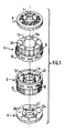
- FIGS 1 to 6 show an internal combustion engine, of the spark-ignition type and whose combustion cycle is two-stroke, to simplify the description below.
- This engine essentially comprises a piston block 1, consisting of two annular pistons 2 and 3 assembled in opposition by their base, of circular cross section, so that these assembled bases constitute a central body 1 a cylindrical and tubular by which the piston block 1 slide axially in the internal bore of a cylindrical casing 4, of circular section, each of the axial ends of which has a radial fixing flange.
- This casing 4 is, at each of its two axial ends, secured to an open axial end of an annular cylinder 5, in the form of a hollow crown.
- annular cylinders 5 are each closed at its axial end opposite to that by which it is secured to the casing, by a bottom 5 a against which is applied one of two circular flanges 6, each having a central opening 7 provided with a bearing 17 to allow the maintenance, the axial passage and the guiding in rotation of a motor shaft 8 or motor output shaft, which crosses coaxially, around its longitudinal axis AA, the casing 4, the two cylinders 5 on the one hand and on the other side of this casing 4, and the two end flanges 6 on either side of the cylinders 5, as well as the piston block 1 formed of the pistons 2 and 3 assembled.
- the monolithic piston block 1 formed by the assembly in opposition of the annular pistons 2 and 3, has a cylindrical and tubular central body 1 a which is pierced, in its middle part, with eight radial guide holes 18, grouped in four pairs of holes which are regularly distributed in circumferential direction around the longitudinal axis of the tubular piston block 1, that is to say which are positioned at 90 ° from each other, the two holes 18 of each pair being further axially spaced one of 1 other, parallel to each other in the same radial plane of the piston block 1.
- each annular piston 2 and 3 comprises a double axial skirt 2 a, 3 a, consisting of two coaxial annular rings, one of which, in an external radial position , is an outer or peripheral ring 9 which is radially spaced from the other, in the internal radial position or internal ring.
- This internal ring essentially consists of a flat ring 10 disposed radially and coaxially, and secured to the corresponding side of the central body 1 a of the piston block 1 by a plurality of axial columns 10 a , and the flat ring 10 is pierced with 11 has axial holes, regularly distributed over its surface in the circumferential direction, and with which are associated valves 11.
- valves 11 are leaf-spring valves which are fixed on the face of the flat ring 10 which faces the body central 1 a of the piston block, and which are prestressed in the closed position of the orifices 11 has drilled in the flat ring 10 of the internal crown, so that the latter can act as an intake pump, ensuring the supply of a cylinder 5 in a combustible mixture, as explained below.
- the outer ring 9 of the double axial skirt 2 a or 3 a of the piston 2 or 3 is shaped as the actual piston head, which is engaged so as to slide axially with sealing in both directions in one of the cylinders annular and hollow 5 (see FIGS. 2 and 5), in which an annular combustion chamber 12 is delimited between the corresponding bottom 5 a of the cylinder 5 and this external radial crown 9.
- the internal radial wall 13 of each cylinder 5 is pierced with intake holes 14, which open into the corresponding combustion chamber 12, when the external radial crown 9 or piston head proper is practically in its bottom dead center position (PMB), that is to say when it is moved axially as far as possible from the bottom 5 a of the corresponding cylinder 5.
- PMB bottom dead center position
- each annular cylinder 5 is pierced with holes 16 which open to the outside of the corresponding cylinder 5 to allow the escape of combustion gases.
- the exhaust holes 16 are grouped in sets of three holes arranged side by side in circumferential direction, these sets of three holes being themselves regularly distributed in this same circumferential direction.
- the two annular cylinders 5 are mounted in opposition, on either side of the housing 4, and being open one towards the other, in such a way that the external radial crown 9 of the double axial skirt 2 a or 3 a of each piston 2 or 3 can move axially in the combustion chamber 12 of the corresponding cylinder 5, the two cylinders 5 being separated from each other with a spacing which corresponds to the axial length of the casing 4.
- the shaft 8 has, at mid-length, a central part 19 which is swollen, of cylindrical shape of circular section, with a larger diameter than the adjacent axial parts of the shaft 8
- a central part 19 In the external lateral face of this central part 19 are formed two grooves 20, of square cross section, which are sinusoidal and peripheral grooves, closing on themselves, or even continuous and endless grooves, and these grooves 20 each form four regular undulations in the longitudinal direction of the shaft 8, and on its periphery, that is to say undulations of the same axial amplitude.
- the housing 4 has four slots 21 drilled radially and extending in the longitudinal direction so as to open into the internal cylindrical bore of the housing 4. These slots 21 are regularly distributed in the circumferential direction around the longitudinal axis of the casing 4, so that they are separated from each other by an angle of 90 °, in order to coincide each with one of the four pairs of guide holes 18 formed radially in the central body 1 a tubular of the piston block 1 shown in Figure 2.
- each of the fingers 22 is thus housed radially through the casing 4 and the piston block 1, so that its internal radial end is housed respectively in one of the two grooves 20 wavy in phase and offset axially along the shaft 8 with the same spacing as that which separates the two radial holes 18 from a pair of holes centered in the same radial plane of the central body 1 a .
- Each of the four pairs of radial fingers 22 is held so that the internal radial end of each of the two corresponding fingers 22 is engaged in that of the two grooves 20 which occupies the corresponding axial position on the central part 19 of the shaft 8, by means of one of four identical cages 23, fixed on the outer part of the casing 4, and each around one of the four slots 21, and each cage 23 contains two ball bearings (not shown) in order to improve the displacement, in the corresponding lumen 21 of the casing 4, of the external radial ends of the two fingers 22 projecting in this lumen 21.
- each of the fingers 22 is divided, substantially at mid-length, into two parts 22 a and 22 b , which allows the internal radial end of the internal radial part 22 a to roll in the corresponding groove 20 of the shaft 8, and at the external radial end of the corresponding external radial part 22 b , to rotate and roll in the cage 23 and in the slot 21 independently of one another, and in particular in the opposite direction.
- each flange 6 and each cylinder 5 have an annular shape and delimit a central opening for the passage of the drive shaft 8, and eight holes 24, equidistant in circumferential direction, are drilled in coincidence and in the axial direction through the flange 6 and the bottom 5 a of the adjacent cylinder, so as to open into the annular combustion chamber 12, to receive spark plugs which will be activated by a common or individual ignition device, not shown .
- the fuel mixture is supplied to the engine assembly by a supply system comprising a supply or intake manifold 25, which extends parallel to the shaft 8 but outside the casing 4, and which itself receives the fuel mixture coming from a carburetor (not shown) by a radial inlet opening 26.
- This inlet manifold 25, longitudinal, has its two ends connected perpendicularly by substantially radial conduits 25 a to two annular end tubes 27 which are applied coaxially against the external axial faces of the two flanges 6.
- each of the two annular tubes 27 is open on the side of the flange 6 corresponding, opposite orifices axial longitudinal 28 formed through the corresponding flange 6, and regularly distributed in circumferential direction, radially inside the spark plug holes 24.
- Each valve 29 can thus be moved axially towards the central body 1a of the piston block 1, so that the valve head is spaced from the corresponding seat machined in the inner axial face of the flange 6 corresponding to let in the combustible mixture in a waiting chamber 30 which is an annular chamber delimited radially between the internal radial wall 13 of the corresponding annular cylinder 5 and an axial sleeve 35, supported coaxially around the shaft 8 by the corresponding flange 6, and extending axially substantially up to the bulged part 19 of the shaft 8, and so that the central body 1 has the piston block 1 slides with sealing around this sleeve 35.
- the internal crown of the corresponding double axial skirt and which is formed by the flat ring 10 and its columns 10 a connecting to the central body 1 a , is also slidably mounted axially in this waiting chamber 30, which is subdivided into two x parts, including an upstream part 30 a , adjacent to the flange 6 and the corresponding valves 29, and of which the other part is a downstream part 30 b , adjacent to the central body 1 a .
- These two parts 30 a and 30 b are separated from each other by the flat ring 10, which slides with sealing on the one hand against the internal radial wall 13 of the corresponding annular cylinder 5 and on the other hand against the sleeve 35 delimiting this chamber 30.
- the internal crown formed of the flat ring 10 with its axial passages 11 a and its valves 11, is secured by the columns 10 a to the central body 1 a , and forms with the waiting chamber 30 a pump admission of fuel mixture into the corresponding annular combustion chamber 12, operating as follows: at start-up, during the first axial strokes of the piston block 1 in the casing 4 and the two cylinders 5, the filling of the combustion chambers 12 is imperfect, but a balance is established very quickly, and the filling becomes normal.
- this piston 2 moves towards its bottom dead center (PMB), that is to say it moves away from the bottom 5 a of the cylinder 5 in which slide the corresponding 9 piston head, which causes the admission of the combustible mixture in the upstream part 30a of the holding chamber 30.
- PMB bottom dead center
- This introduction of combustible mixture into this combustion chamber 12 drives out the gases previously burned in this chamber through the holes d 'exhaust 16 leading to peripheral tubes 31 connected to an exhaust manifold 32.
- the corresponding inner ring and its flat ring 10 undergo the same axial translation, which has for effect of compressing the upstream part 30 a of the chamber 30, while the downstream part 30 b is dilated.
- the intake pump constituted by the cooperation of the flat ring 10 of the inner ring of the double axial skirt of each piston 2 or 3, with the corresponding waiting chamber 30, operates as a fuel mixture suction pump in the upstream part 30 a this chamber and discharge of the combustible mixture of the downstream portion 30 b of the chamber inwardly of the corresponding 12 annular combustion chamber, after transfer of the upstream portion 30a to the downstream portion 30b.
- the intake pumps thus produced are therefore subjected to the same alternating axial movements as the pistons, which are the driving elements for the pumps and drive them, but which can only deliver their driving force because of the supply of fuel mixture provided by these pumps.
- Each outer ring 9, forming the actual piston head, of the corresponding piston 2 or 3 has internal and external segments 34 which allow good sealing against the inner and opposite cylindrical faces of the outer 15 and inner 13 radial walls defining the annular combustion chamber 12.
- the four pairs of radial fingers 22 transform the translational movement of the piston block 1 into a rotary movement of the motor shaft 8, by the fact that any axial movement of the piston block 1 causes the fingers 22 in a translational movement of the same amplitude, and these fingers 22 roll by their internal radial end in the corrugated grooves 20 of the shaft 8, causing a rotary movement of the latter.
- the axial spacing of the two holes 18 of a pair of holes in a particular angular position at the periphery of the central body 1 a corresponds to the spacing of the two corrugated grooves 20 of the central part 19 of the 'shaft 8 shown in Figure 4, and the height or amplitude of a ripple is substantially equal to the axial stroke of the piston 1.
- the radial fingers 22 can rotate on themselves in the holes 18 of the block piston 1 by means of needle bearings 33 mounted in each of these holes 18, as shown in FIGS. 5 and 6.
- the movement transformation mechanism is reversed, insofar as radial fingers are housed and retained in the bulged central part 19 of the motor shaft 8, so that one at less of their ends, in the external radial position, is engaged and can roll in one of the sinusoidal grooves formed in the cylindrical face in the internal radial position on the annular piston block 1, and in particular on its central body 1 a .
- each of the flanges 6 is necessary to ensure the admission of oxidant gas and / or fuel to the annular combustion chambers 12, as well as for the mounting and guiding of the rotary shaft. 8.
- these flanges 6 are only pierced with spark plug receiving holes if the engine is of the spark-ignition type. If this engine is a diesel engine, there is no need to drill the flanges 6 and the bottoms 5 has cylinders 5 for the spark plug housing.
- the internal combustion engine according to the invention finds more particularly its application for the equipment of airplanes and other types of aerodynes, because of the facility which it presents to adapt the rotation speed of the shaft. to the nature of the use, but, of course, such an engine can be used to equip marine or land vehicles.
Landscapes
- Engineering & Computer Science (AREA)
- Mechanical Engineering (AREA)
- General Engineering & Computer Science (AREA)
- Chemical & Material Sciences (AREA)
- Combustion & Propulsion (AREA)
- Cylinder Crankcases Of Internal Combustion Engines (AREA)
- Combustion Methods Of Internal-Combustion Engines (AREA)
Description
La présente invention se rapporte aux moteurs à combustion interne à pistons annulaires, montés en opposition et solidaires, et à arbre moteur central, ces moteurs utilisant des carburants tels que le gas-oil, le kérosène, l'essence etc.... et pouvant comporter, deux, quatre, six, huit cylindres et plus.The present invention relates to internal combustion engines with annular pistons, mounted in opposition and integral with each other, and with a central drive shaft, these engines using fuels such as diesel, kerosene, petrol, etc ... and may have two, four, six, eight cylinders or more.
Actuellement, les moteurs commercialisés du type à combustion interne, munis de pistons classiques, consomment une grande quantité d'énergie pour délivrer une faible puissance utile. Ce rendement relativement faible est dû principalement à la conception des organes mobiles constitués par les pistons, les bielles, le vilebrequin et les soupapes. Ces moteurs classiques sont de plus fragilisés par le grand nombre de pièces mobiles qu'ils comprennent et qui sont soumises à des efforts permanents et importants.Currently, commercial internal combustion type engines, fitted with conventional pistons, consume a large amount of energy to deliver a low useful power. This relatively low efficiency is mainly due to the design of the movable members constituted by the pistons, the connecting rods, the crankshaft and the valves. These conventional motors are further weakened by the large number of moving parts which they comprise and which are subjected to permanent and significant forces.
Dans le but de remédier à ces inconvénients, il a été déjà proposé par le brevet anglais n° 11.027 un moteur à combustion interne fonctionnant avec un meilleur rendement énergétique et de construction considérablement simplifiée.In order to remedy these drawbacks, it has already been proposed by English patent No. 11,027 an internal combustion engine operating with better fuel efficiency and considerably simplified construction.
L'avantage du moteur proposé dans ce brevet anglais réside dans la suppression des bielles et du vilebrequin, ce qui permet en outre d'obtenir un moteur dont la vitesse de rotation est adaptée à son utilisation, sans nuire à son rendement.The advantage of the engine proposed in this English patent resides in the elimination of the connecting rods and the crankshaft, which also makes it possible to obtain an engine whose speed of rotation is adapted to its use, without adversely affecting its performance.
Dans le moteur à combustion interne selon le brevet anglais n° 11.027, deux cylindres annulaires sont disposés chacun d'un côté d'un organe central ondulé, et en s'ouvrant l'un vers l'autre, et deux pistons annulaires, montés en opposition et chacun d'un côté de l'organe central ondulé, sont montés de sorte que la tête de chacun des pistons annulaires coulisse avec étanchéité dans l'un des cylindres annulaires. Ainsi, le mouvement alternatif des pistons est transformé en un mouvement rotatif de l'arbre moteur central, qui traverse coaxialement les cylindres et pistons annulaires, par l'intermédiaire de l'organe central ondulé, qui est solidaire de l'arbre central.In the internal combustion engine according to English Patent No. 11,027, two annular cylinders are each arranged on one side of a central corrugated member, and opening towards one another, and two annular pistons, mounted in opposition and each on one side of the corrugated central member, are mounted so that the head of each of the annular pistons slides with sealing in one of the annular cylinders. Thus, the reciprocating movement of the pistons is transformed into a rotary movement of the central drive shaft, which coaxially passes through the annular cylinders and pistons, by means of the corrugated central member, which is integral with the central shaft.
Les pistons annulaires coopèrent chacun avec l'organe central ondulé s'étendant sensiblement radialement entre eux, par rapport à l'axe de rotation de l'arbre central, de telle sorte que les pistons s'éloignent simultanément l'un de l'autre ou se rapprochent simultanément l'un de l'autre. L'organe central ondulé est un plateau radial ayant un bord ondulé et dont chacune des faces opposées reçoit la poussée de l'un des pistons, par l'intermédiaire de doigts axiaux, interposés entre la base de chaque piston annulaire et la face en regard du disque radial ondulé, les doigts axiaux associés à l'un des pistons occupant des positions décalées en direction circonférentielle par rapport aux doigts axiaux associés à l'autre piston. De plus, ces pistons présentent des saillies radiales vers l'intérieur, qui pénètrent dans une gorge ménagée dans la périphérie externe du plateau, dans le but de maintenir les pistons toujours en contact avec le plateau, alors que la poussée des pistons est appliquée au plateau par les doigts. Ces doigts axiaux sont retenus par des broches radiales qui se prolongent vers l'extérieur par des saillies pénétrant dans des gorges longitudinales ménagées dans le carter reliant les deux cylindres annulaires l'un à l'autre, de sorte que les pistons sont guidés en déplacement axial alternatif dans les cylindres fixes en rotation, si l'arbre central est un arbre moteur rotatif.The annular pistons each cooperate with the corrugated central member extending substantially radially between them, relative to the axis of rotation of the central shaft, so that the pistons move away from each other simultaneously or approach each other simultaneously. The central corrugated member is a radial plate having a corrugated edge and each of the opposite faces of which receives the thrust of one of the pistons, by means of axial fingers, interposed between the base of each annular piston and the opposite face. of the corrugated radial disc, the axial fingers associated with one of the pistons occupying positions offset in the circumferential direction relative to the axial fingers associated with the other piston. In addition, these pistons have inward radial projections, which penetrate into a groove formed in the external periphery of the plate, in order to keep the pistons always in contact with the plate, while the thrust of the pistons is applied to the tray by fingers. These axial fingers are retained by radial pins which extend towards the outside by projections penetrating into longitudinal grooves formed in the casing connecting the two annular cylinders to each other, so that the pistons are guided in alternating axial movement in the fixed cylinders in rotation, if the central shaft is a rotary drive shaft.
Si le moteur est à allumage commandé, le mélange combustible est alimenté par l'arbre moteur creux, par l'intermédiaire d'un boisseau cylindrique, solidaire des cylindres et logé dans l'arbre creux, de sorte que le mélange combustible parvient tout d'abord dans la chambre délimitée entre les deux pistons annulaires et pénètre ensuite dans les chambres de combustion annulaires, entre les têtes de pistons et le fond des cylindres annulaires, lorsque les pistons annulaires se rapprochent l'un de l'autre, dans un cycle à quatre temps comme dans un cycle à deux temps, le passage du mélange combustible étant assuré dans des canaux axiaux s'étendant sur une certaine distance axiale dans la face interne de la paroi radiale interne des cylindres annulaires, et s'ouvrant dans les chambres de combustion en regard d'une partie incurvée de la tête de piston annulaire correspondante. L'échappement des gaz brûlés est effectué par des orifices d'échappement percés dans la paroi radiale externe de chaque cylindre annulaire. Lorsque les pistons sont repoussés l'un vers l'autre par l'explosion du mélange combustible dans les chambres de combustion, les doigts axiaux correspondants transmettent cette poussée aux ondulations du disque central, et sont ainsi contraints de se déplacer contre les parties inclinées des ondulations, ce qui provoque la rotation du disque ondulé, et donc de l'arbre, tandis que l'écartement des deux pistons l'un de l'autre résulte de la rotation de ce disque ondulé dont les parties inclinées contraignent les doigts axiaux à repousser les pistons vers le fond des chambres de combustion correspondantes, sous l'effet de l'inertie de rotation acquise par le disque ondulé et l'arbre.If the engine is with spark ignition, the fuel mixture is supplied by the hollow engine shaft, by means of a cylindrical plug, integral with the cylinders and housed in the hollow shaft, so that the fuel mixture reaches all first in the chamber delimited between the two annular pistons and then enters the annular combustion chambers, between the piston heads and the bottom of the annular cylinders, when the annular pistons approach each other, in a cycle four-stroke as in a two-stroke cycle, the passage of the fuel mixture being ensured in axial channels extending over a certain axial distance in the internal face of the internal radial wall of the annular cylinders, and opening in the chambers combustion opposite a curved part of the corresponding annular piston head. The exhaust of the burnt gases is effected by exhaust orifices drilled in the external radial wall of each annular cylinder. When the pistons are pushed towards each other by the explosion of the combustible mixture in the combustion chambers, the corresponding axial fingers transmit this thrust to the corrugations of the central disc, and are thus forced to move against the inclined parts of the corrugations, which causes the rotation of the corrugated disc, and therefore of the shaft, while the spacing of the two pistons from each other results from the rotation of this corrugated disc whose inclined parts force the axial fingers to push the pistons towards the bottom of the corresponding combustion chambers, under the effect of the inertia of rotation acquired by the corrugated disc and the shaft.
Dans des variantes de réalisation, la base de chacun des pistons annulaires présente un profil ondulé, qui correspond aux ondulations du disque central, et qui vient en contact avec ces ondulations par l'intermédiaire d'organes de roulement tels que des billes. Dans ce cas, les saillies des ondulations d'un piston correspondent aux évidements des ondulations du piston opposé, pour obtenir des mouvements d'écartement simultané ou de rapprochement simultané des deux pistons.In alternative embodiments, the base of each of the annular pistons has a corrugated profile, which corresponds to the corrugations of the central disc, and which comes into contact with these corrugations by means of rolling members such as balls. In this case, the projections of the undulations of a piston correspond to the recesses of the undulations of the opposite piston, in order to obtain movements of simultaneous separation or simultaneous bringing together of the two pistons.
Dans une autre variante, les pistons ont également leur base ondulée, mais le disque central ondulé est remplacé par un organe en forme de croix, solidaire de l'arbre, et portant des paires de galets positionnés de sorte qu'elles viennent en contact avec les bords ondulés des deux pistons qui, dans ce cas, présentent des ondulations parfaitement correspondantes, c'est-à-dire que les saillies des ondulations d'un piston sont en face des saillies des ondulations du piston opposé, de telle manière que les pistons s'éloignent ou se rapprochent simultanément l'un de l'autre, comme dans tous les autres cas décrits dans ce brevet anglais.In another variant, the pistons also have their corrugated base, but the corrugated central disc is replaced by a cross-shaped member, integral with the shaft, and carrying pairs of rollers positioned so that they come into contact with the wavy edges of the two pistons which, in this case, have perfectly corresponding corrugations, that is to say that the projections of the corrugations of one piston are opposite the projections of the corrugations of the opposite piston, so that the pistons move away from or approach each other simultaneously, as in all the other cases described in this English patent.
L'allumage est assuré par des bougies montées dans les fonds des cylindres, et le nombre ainsi que la forme des ondulations dépendront du type de moteur et de la vitesse de rotation désirée.The ignition is ensured by candles mounted in the bottoms of the cylinders, and the number and the shape of the corrugations will depend on the type of engine and the desired speed of rotation.
Des perfectionnements à ce moteur ont été proposés dans le brevet US N° 4.090.478, qui décrit un moteur multicylindre et sinusoïdal. Ce moteur comprend un carter constitué par l'assemblage de deux troncs de cylindres, et qui présente un alésage cylindrique central, pour le passage d'un arbre creux présentant, dans sa surface latérale externe, deux paires de gorges ondulées, décalées axialement et à ondulations sinusoïdales, l'alésage central étant entouré de plusieurs alésages cylindriques, répartis régulièrement en direction périphérique autour de l'alésage cylindrique central et d'axes parallèles à celui de ce dernier. Dans chaque alésage cylindrique périphérique sont logés deux pistons indépendants, dont les têtes de pistons sont tournées l'une vers l'autre de façon à délimiter entre elles une unique chambre de combustion par cylindre périphérique, et chacun des pistons est relié par un mécanisme d'accouplement à une paire de gorges sinusoïdales, pour la transformation du mouvement axial alternatif des pistons en un mouvement de rotation de l'arbre creux central.Dans ce moteur, les deux pistons indépendants logés dans chaque alésage cylindrique circulaire périphérique sont des pistons qui se rapprochent ou s'éloignent simultanément, et l'admission de mélange combustible dans la chambre de combustion délimitée entre les deux pistons, ainsi que l'échappement des gaz brûlés de cette chambre de combustion sont assurés axialement dans l'arbre creux puis, radialement, par un système complexe de soupapes et clapets.De même, l'allumage est assuré partiellement par l'intérieur de l'arbre central creux, et à l'aide d'un mécanisme complexe. Le mécanisme d'accouplement de chacun des pistons à une paire de gorges sinusoïdales de l'arbre central creux comprend deux poussoirs parallélépipédiques logés dans des passages radiaux de forme correspondante des pistons et écartés l'un de l'autre radialement par des ressorts, de sorte que l'un soit appliqué contre la surface latérale externe de l'arbre creux par l'intermédiaire de billes retenues dans des logements en portion de sphère évidés dans la face radiale interne de ce poussoir et engagées simultanément dans les rainures sinusoïdales de l'arbre, tandis que l'autre poussoir, en position radiale externe, est appliqué contre la face radiale interne du carter par l'intermédiaire de billes, également logées dans des évidements en portion de sphère ménagés dans la face radiale externe de ce poussoir et reçues par ailleurs dans des lumières longitudinales usinées dans la face interne du carter.Improvements to this engine have been proposed in US Patent No. 4,090,478, which describes a multicylinder and sinusoidal engine. This motor comprises a casing constituted by the assembly of two trunks of cylinders, and which has a central cylindrical bore, for the passage of a hollow shaft having, in its external lateral surface, two pairs of corrugated grooves, offset axially and at sinusoidal undulations, the central bore being surrounded by several cylindrical bores, distributed regularly in the peripheral direction around the central cylindrical bore and axes parallel to that of the latter. In each peripheral cylindrical bore are housed two independent pistons, the piston heads of which are turned towards one another so as to delimit between them a single combustion chamber per peripheral cylinder, and each of the pistons is connected by a mechanism of coupling to a pair of sinusoidal grooves, for the transformation of the reciprocating axial movement of the pistons into a rotational movement of the central hollow shaft. In this motor, the two independent pistons housed in each peripheral circular cylindrical bore are pistons which approach or move away simultaneously, and the admission of fuel mixture into the combustion chamber delimited between the two pistons, as well as the exhaust of the burnt gases of this combustion chamber are provided axially in the hollow shaft and then, radially, by a complex system of valves and valves. Likewise, ignition is ensured partially by the interior of the hollow central shaft, and at the using a complex mechanism. The coupling mechanism of each of the pistons to a pair of sinusoidal grooves of the hollow central shaft comprises two parallelepipedic pushers housed in radial passages of corresponding shape of the pistons and separated from one another radially by springs, of so that one is applied against the external lateral surface of the hollow shaft by means of balls retained in housings in a portion of a sphere hollowed out in the internal radial face of this pusher and engaged simultaneously in the sinusoidal grooves of the shaft, while the other pusher, in the external radial position, is applied against the internal radial face of the casing by means of balls, also housed in recesses in the portion of a sphere formed in the external radial face of this pusher and received moreover in longitudinal slots machined in the internal face of the casing.
Il en résulte qu'un tel moteur présente une structure extrêmement complexe, et que ses coûts de fabrication et de maintenance sont très élevés.As a result, such an engine has an extremely complex structure, and its manufacturing and maintenance costs are very high.
On connaît également par le brevet US-3.786.790 un moteur à combustion interne à piston à double action monté alternatif dans un carter à deux chambres séparées l'une de l'autre par une cloison annulaire fixe. Dans chacune des deux chambres est logé un piston annulaire entourant un arbre moteur central qui traverse la cloison et, coaxialement, l'ensemble du carter, et les deux pistons annulaires sont solidaires l'un de l'autre par un manchon annulaire entourant également l'arbre central et traversant la cloison. Les deux pistons annulaires forment ainsi un bloc piston monolitique qui coulisse axialement et alternativement dans un sens et dans l'autre dans le carter. Une seule chambre de combustion est aménagée dans la cloison intermédiaire de séparation des deux chambres dans lesquelles coulissent les pistons annulaires. La chambre de combustion comporte de plus un clapet à bille mettant alternativement l'une des deux chambres du carter en communication avec la chambre de combustion, de sorte que le temps de combustion et d'expansion d'un mélange combustible provoque le déplacement d'un piston vers le fond correspondant du cylindre et simultanément la compression par l'autre piston du mélange combustible,préalablement admis dans la chambre de carter correspondante, vers la chambre de combustion dans laquelle la bille de clapet est déplacée pour obturer la communication avec l'autre chambre. Dans ce moteur également, la transformation du mouvement axial alternatif des pistons en mouvement de rotation de l'arbre central est assurée par des billes engagées partiellement dans un logement en calotte sphérique ménagé dans la surface latérale interne du manchon de liaison des deux pistons, ainsi que dans une rainure ondulée, de forme sensiblement sinusoïdale, ménagée dans la périphérie de l'arbre central.Also known from US Pat. No. 3,786,790 is an internal combustion piston engine with double action reciprocally mounted in a casing with two chambers separated from each other by a fixed annular partition. In each of the two chambers is housed an annular piston surrounding a central drive shaft which passes through the partition and, coaxially, the entire casing, and the two annular pistons are integral with one another by an annular sleeve also surrounding the central shaft and passing through the partition. The two annular pistons thus form a monolithic piston block which slides axially and alternately in one direction and in the other in the casing. A single combustion chamber is arranged in the intermediate partition separating the two chambers in which the annular pistons slide. The combustion chamber further comprises a ball valve alternately placing one of the two chambers of the casing in communication with the combustion chamber, so that the combustion and expansion time of a combustible mixture causes the displacement of a piston towards the corresponding bottom of the cylinder and simultaneously the compression by the other piston of the combustible mixture, previously admitted into the corresponding housing chamber, towards the combustion chamber in which the valve ball is moved to close the communication with the other room. Also in this engine, the transformation of the alternating axial movement of the pistons into the rotation movement of the central shaft is ensured by balls partially engaged in a spherical cap housing formed in the internal lateral surface of the connecting sleeve of the two pistons, thus than in a corrugated groove, of substantially sinusoidal shape, formed in the periphery of the central shaft.
L'inconvénient d'un tel moteur réside essentiellement dans les sollicitations extrêmes subies par le clapet à bille monté dans l'unique chambre de combustion ménagée dans la paroi intermédiaire, ainsi que dans la réalisation de cette chambre de combustion et du clapet à bille associé.The disadvantage of such an engine lies essentially in the extreme stresses undergone by the ball valve mounted in the single combustion chamber formed in the intermediate wall, as well as in the production of this combustion chamber and of the associated ball valve.
Par la présente invention, on se propose de perfectionner les moteurs à combustion connus par le brevet anglais GB 11.027, sans utiliser une structure aussi complexe et coûteuse que celle des moteurs selon le brevet US 4.090.478, mais d'une fiabilité et d'un rendement supérieurs à ceux des moteurs selon le brevet US 3.486.790, qui ne peuvent fonctionner qu'en combinaison avec des systèmes d'admission et d'échappement relativement complexes comportant un grand nombre de clapets.By the present invention, it is proposed to improve the combustion engines known by the English patent GB 11,027, without using a structure as complex and expensive as that of the engines according to US Pat. No. 4,090,478, but with reliability and higher efficiency than those of engines according to US Patent 3,486,790, which can only operate in combination with relatively complex intake and exhaust systems comprising a large number of valves.
On connaît déjà par les demandes de brevet DE-A-3226379 et DE-A-290893 des moteurs à combustion interne sensiblement du type de ceux décrits dans GB 11027 et comportant des pistons formant des ensembles rigides et fonctionnant comme blocs monolithiques. Le mécanisme de transformation qui accouple le bloc piston et l'arbre dans DE-3226379 est constitué par des doigts radiaux retenus dans le bloc piston et engagés pour suivre les ondulations autour de l'arbre.Already known from patent applications DE-A-3226379 and DE-A-290893 are internal combustion engines substantially of the type described in GB 11027 and comprising pistons forming rigid assemblies and operating as monolithic blocks. The transformation mechanism which couples the piston block and the shaft in DE-3226379 consists of radial fingers retained in the piston block and engaged to follow the undulations around the shaft.
Le moteur à combustion interne selon l'invention, qui peut être un moteur à allumage commandé, du type à deux ou quatre temps, à essence, ou encore un moteur diesel, fonctionnant avec une pompe d'alimentation, ou un turbo-compresseur, un carburateur ou une pompe à injection, et pouvant être combiné à une boîte à vitesses un embrayage, et, le cas échéant, à une dynamo, une batterie, etc...., est un moteur du type connu par le brevet anglais GB 11.027 et comportant au moins un arbre moteur, entraîné en rotation par au moins un ensemble moteur que l'arbre traverse coaxialement, et qui comprend un carter cylindrique, dont chaque extrémité axiale est solidaire de l'un de deux cylindres annulaires et creux, ouverts l'un vers l'autre et fermés chacun par un fond du côté opposé, et deux pistons annulaires guidés en translation axiale dans le carter, dans lequel ils sont montés en opposition, de sorte que chacun d'eux présente une tête de piston engagés à coulissement axial étanche et alternatif dans l'un respectivement des deux cylindres annulaires, dans chacun desquels une chambre de combustion annulaire est délimitée entre le fond de cylindre correspondant et la tête de piston. Chaque chambre de combustion est alimentée par un système d'admission d'un gaz comburant et/ou d'un carburant et est en communication, au travers de la paroi radiale externe du cylindre annulaire correspondant, avec un système d'échappement des gaz brûlés. Les deux pistons, le carter, les deux cylindres et l'arbre sont montés coaxiaux autour de l'axe longitudinal de l'arbre, et les déplacements axiaux alternatifs des pistons sont transformés en rotation de l'arbre autour de son axe par un mécanisme de transformation de mouvement accouplant les pistons à une partie centrale de l'arbre, et comportant des doigts, dont une extrémité de chacun est astreinte à suivre des ondulations sans fin, périphériques autour de l'axe de l'arbre et de même amplitude axiale, qui sont présentées par un organe rigide, les deux pistons étant solidaires l'un de l'autre par leur base et constituent un bloc-piston monolithique, dont un corps central coulisse dans le carter de sorte que les deux pistons se déplacent simultanément en direction axiale et alternativement dans un sens et dans l'autre, et les doigts du mécanisme de transformation de mouvement étant des doigts radiaux, retenus dans l'un des deux organes rigides constitués par la partie centrale de l'arbre et par le corps central du bloc-piston, tandis que les ondulations sont définies par au moins une rainure ménagée dans une surface axiale de l'autre organe rigide, et dans laquelle ou lesquelles est engagée une extrémité de chaque doigt radial.The internal combustion engine according to the invention, which can be a spark ignition engine, of the two or four stroke type, petrol, or even a diesel engine, operating with a feed pump, or a turbo-compressor, a carburetor or an injection pump, and which can be combined with a gearbox, a clutch, and, where appropriate, with a dynamo, a battery, etc., is an engine of the type known by the English patent GB 11.027 and comprising at least one motor shaft, driven in rotation by at least one motor assembly that the shaft crosses coaxially, and which comprises a cylindrical casing, each axial end of which is integral with one of two annular and hollow cylinders, open towards one another and each closed by a bottom on the opposite side, and two annular pistons guided in axial translation in the casing, in which they are mounted in opposition, so that each of them has a piston head engaged in sealed and reciprocating axial sliding in one respectively of the two annular cylinders, in each which an annular combustion chamber is delimited between the corresponding cylinder bottom and the piston head. Each combustion chamber is supplied by an intake system of an oxidizing gas and / or a fuel and is in communication, through the external radial wall of the corresponding annular cylinder, with an exhaust system for the burnt gases. . The two pistons, the casing, the two cylinders and the shaft are mounted coaxial around the longitudinal axis of the shaft, and the alternating axial displacements of the pistons are transformed into rotation of the shaft around its axis by a mechanism transforming movement coupling the pistons to a central part of the shaft, and comprising fingers, one end of each of which is required to follow endless undulations, peripheral around the axis of the shaft and of the same axial amplitude , which are presented by a rigid member, the two pistons being integral with one another by their base and constitute a monolithic piston block, of which a central body slides in the casing so that the two pistons move simultaneously in axial direction and alternately in one direction and in the other, and the fingers of the movement transformation mechanism being radial fingers, retained in one of the two rigid members constituted by the central part of the shaft and by the central body of the piston block, while the corrugations are defined by at least one groove formed in an axial surface of the another rigid member, and in which one or which is engaged one end of each radial finger.
Le moteur proposé par l'invention est caractérisé en ce que le bloc piston comporte, à chacune de ses extrémités axiales, une double jupe axiale comprenant deux couronnes annulaires coaxiales autour de l'axe de l'arbre et espacées radialement l'une de l'autre, et dont l'une, en position radiale externe, constitue la tête de piston annulaire proprement dite, coulissant dans un cylindre annulaire et comportant des segments radiaux externes et internes glissant contre les parois respectivement externe et interne du cylindre annulaire correspondant, tandis que la couronne annulaire en position radiale interne sur la double jupe guide le bloc piston dans ses déplacements axiaux par coulissement à l'intérieur de la paroi interne de ce cylindre annulaire, la couronne interne de chaque jupe double du bloc piston est avantageusement creuse et comporte un anneau plat et radial, qui est axialement espacé du corps central du bloc piston auquel il est solidarisé par au moins une colonne sensiblement axiale et rigide, et qui coulisse axialement avec étanchéité dans une chambre d'attente annulaire, délimitée entre la paroi interne du cylindre annulaire correspondant et un manchon coaxial, entourant l'arbre et fixe vis-à-vis du cylindre, correspondant, l'anneau plat de chaque couronne interne étant alors percé d'ouvertures axiales régulièrement réparties sur sa surface et associées à des clapets, de sorte que la couronne interne forme, avec la chambre d'attente, une pompe d'admission de gaz comburant et/ou de carburant dans la chambre de combustion correspondante, et dans laquelle les clapets sont destinés, d'une part, à ouvrir le passage par les ouvertures vers l'intérieur de cette couronne interne, lorsque cette dernière se déplace avec la tête de piston correspondante vers le fond du cylindre correspondant, afin d'admettre dans cette couronne interne creuse du gaz carburant et/ou du carburant disponible dans la chambre d'attente, et, d'autre part, à fermer les ouvertures de l'anneau plat lorsque cette couronne interne se déplace avec la tête de piston correspondante vers l'autre cylindre, afin de refouler du gaz comburant et/ou du carburant dans la chambre de combustion correspondante, par des orifices percés dans la paroi interne du cylindre correspondant, de préférence à proximité du point mort bas du piston annulaire correspondant.The engine proposed by the invention is characterized in that the piston block comprises, at each of its axial ends, a double axial skirt comprising two annular coaxial rings around the axis of the shaft and radially spaced one of the 'other, and one of which, in the external radial position, constitutes the actual annular piston head, sliding in an annular cylinder and comprising external and internal radial segments sliding against the respectively external and internal walls of the corresponding annular cylinder, while that the annular crown in the internal radial position on the double skirt guides the piston block in its axial displacements by sliding inside the internal wall of this annular cylinder, the internal crown of each double skirt of the piston block is advantageously hollow and comprises a flat and radial ring, which is axially spaced from the central body of the piston block to which it is secured by at least one column e substantially axial and rigid, and which slides axially with sealing in an annular waiting chamber, delimited between the internal wall of the corresponding annular cylinder and a coaxial sleeve, surrounding the shaft and fixed opposite the corresponding cylinder, the flat ring of each internal ring then being pierced with axial openings regularly distributed over its surface and associated with valves, so that the internal crown forms, with the waiting chamber, a pump for admitting oxidant gas and / or fuel into the corresponding combustion chamber, and in which the valves are intended, on the one hand, to open the passage through the openings towards the inside of this internal ring, when the latter moves with the corresponding piston head towards the bottom of the corresponding cylinder, in order to admit into this hollow internal ring fuel gas and / or fuel available in the chamber d '' and, on the other hand, to close the openings of the flat ring when this internal ring moves with the corresponding piston head towards the other cylinder, in order to push oxidant gas and / or fuel into the corresponding combustion chamber, through holes drilled in the internal wall of the corresponding cylinder, preferably near the bottom dead center of the corresponding annular piston.
Selon des variantes de réalisation du moteur selon l'invention, l'arbre moteur peut traverser un seul ensemble moteur et être actionné par celui-ci, ou encore l'arbre moteur peut traverser plusieurs ensembles moteurs et être actionné par un ou plusieurs de ceux-ci, ce qui permet de laisser un ou plusieurs ensembles moteurs au repos.According to alternative embodiments of the motor according to the invention, the motor shaft can pass through a single motor assembly and be actuated by it, or else the motor shaft can pass through several motor assemblies and be actuated by one or more of those -ci, which allows to leave one or more engine assemblies at rest.
De plus, dans chaque ensemble moteur, l'écartement des cylindres annulaires est bien entendu déterminé par la longueur axiale du carter commun qui les sépare, de telle sorte que lorsqu'un piston annulaire est à son point mort haut (P.M.H.), l'autre piston annulaire se trouve à son point mort bas (P.M.B.) dans l'autre cylindre annulaire.In addition, in each engine assembly, the spacing of the annular cylinders is of course determined by the axial length of the common casing which separates them, so that when an annular piston is at its top dead center (TDC), the another annular piston is at its bottom dead center (PMB) in the other annular cylinder.
Enfin, lorsque les efforts transmis entre les pistons et l'arbre central nécessitent leur distribution simultanément sur plusieurs rainures ondulées, les ondulations de ces rainures sont obligatoirement en phase.Finally, when the forces transmitted between the pistons and the central shaft require their distribution simultaneously over several grooves wavy, the corrugations of these grooves are necessarily in phase.
Dans une forme de réalisation avantageusement simple et fiable du mécanisme de transformation de mouvement, la partie centrale de l'arbre est une partie cylindrique renflée, de plus grand diamètre que les parties axiales adjacentes de l'arbre qui sont logées dans l'ensemble moteur, et dans la surface latérale cylindrique de laquelle est ménagée chaque rainure ondulée dans laquelle se déplacent les extrémités radiales internes des doigts traversant radialement le corps central présenté par le bloc piston et qui est tubulaire et coulisse axialement autour de la partie centrale renflée de l'arbre, chaque rainure dans cette partie centrale formant des ondulations régulières dont le nombre est fonction de la vitesse de rotation désirée pour l'arbre.In an advantageously simple and reliable embodiment of the movement transformation mechanism, the central part of the shaft is a swollen cylindrical part, of larger diameter than the adjacent axial parts of the shaft which are housed in the motor assembly , and in the cylindrical lateral surface of which is formed each corrugated groove in which the internal radial ends of the fingers move crossing radially the central body presented by the piston block and which is tubular and slides axially around the swollen central part of the shaft, each groove in this central part forming regular undulations, the number of which depends on the desired speed of rotation for the shaft.
Avantageusement, pour assurer une bonne distribution périphérique des efforts, simultanément sur les différentes ondulations d'une rainure de l'arbre, ainsi que des ondulations d'une rainure aux ondulations de la ou des autres rainures de l'arbre, le corps central du bloc piston annulaire est, selon l'invention, traversé dans sa partie médiane par des trous radiaux de guidage des doigts, ces trous étant groupés en au moins deux ensembles identiques d'au moins deux trous chacun, les différents ensembles de trous étant équidistants les uns des autres en direction circonférentielle autour de l'axe de l'arbre, et les trous de chaque ensemble étant parallèles les uns aux autres et décalés axialement dans un même plan radial, tandis que la partie centrale renflée de l'arbre présente des rainures ondulées en phase, en nombre égal au nombre de trous par ensemble de trous, et décalées axialement en correspondance avec les décalages axiaux des trous de chaque ensemble de trous.Advantageously, to ensure good peripheral distribution of the forces, simultaneously on the various undulations of a groove in the shaft, as well as undulations of a groove on the undulations of the other groove or grooves, the central body of the According to the invention, the annular piston block is traversed in its middle part by radial finger guide holes, these holes being grouped into at least two identical sets of at least two holes each, the different sets of holes being equidistant from each other. from each other in circumferential direction around the axis of the shaft, and the holes of each assembly being parallel to each other and offset axially in the same radial plane, while the central swollen part of the shaft has grooves wavy in phase, in number equal to the number of holes per set of holes, and offset axially in correspondence with the axial offsets of the holes of each set of holes.
Avantageusement de plus, les doigts radiaux du dispositif de transformation de mouvement sont simultanément utilisés pour assurer le guidage axial du bloc-piston dans l'ensemble constitué par le carter et les deux cylindres annulaires. A cet effet, selon l'invention, le carter présente des lumières axiales, débouchant dans son alésage cylindrique, et chacune placée radialement en vis-à-vis d'un ensemble de trous du bloc piston, les doigts radiaux logés dans les trous de cet ensemble ayant chacun son extrémité radiale externe engagée dans la lumière correspondante, qui les guide ainsi axialement avec le bloc piston dans le carter.Advantageously moreover, the radial fingers of the movement transformation device are simultaneously used to ensure the axial guidance of the piston block in the assembly formed by the casing and the two annular cylinders. To this end, according to the invention, the casing has axial openings, opening into its cylindrical bore, and each placed radially opposite a set of holes in the piston block, the radial fingers housed in the holes this assembly each having its external radial end engaged in the corresponding lumen, which thus guides them axially with the piston block in the casing.
Afin de garantir une bonne coopération des doigts radiaux avec les rainures correspondantes de l'arbre, l'extrémité radiale interne de chacun des doigts traversant un même ensemble de trous percés dans le bloc piston, est maintenue engagée dans une rainure ondulée de la partie centrale de l'arbre par une cage, fixée sur la face externe du carter autour de la lumière correspondante, et unie de roulements assurant une bonne circulation des extrémités radiales externes de ces doigts dans ladite lumière correspondante. De plus, la partie de chaque doigt qui traverse le bloc piston est avantageusement montée dans le trou correspondant ménagé dans le bloc piston par l'intermédiaire d'au moins un roulement à aiguilles.In order to guarantee good cooperation of the radial fingers with the corresponding grooves of the shaft, the internal radial end of each of the fingers passing through the same set of holes drilled in the piston block is kept engaged in a corrugated groove in the central part. of the shaft by a cage, fixed on the external face of the casing around the corresponding lumen, and united with bearings ensuring good circulation of the external radial ends of these fingers in said corresponding lumen. In addition, the part of each finger which passes through the piston block is advantageously mounted in the corresponding hole formed in the piston block by means of at least one needle bearing.
En outre, il est avantageux que chaque doigt radial guidé dans un trou radial et dans une lumière qui traversent respectivement le bloc piston et le carter, soit fractionné, sensiblement à mi-longueur, en deux parties disposées bout à bout et telles que l'extrémité radiale interne de la partie radiale interne du doigt et l'extrémité radiale externe de la partie radiale externe du doigt sont engagées et peuvent tourner indépendamment l'une de l'autre, et éventuellement en sens contraire, respectivement dans la rainure correspondante de l'arbre et dans la lumière correspondante du carter.In addition, it is advantageous for each radial finger guided in a radial hole and in a lumen which respectively pass through the piston block and the casing, to be divided, substantially at mid-length, into two parts arranged end to end and such that the internal radial end of the internal radial part of the finger and the external radial end of the external radial part of the finger are engaged and can rotate independently of each other, and possibly in opposite directions, respectively in the corresponding groove of the shaft and in the corresponding light of the casing.
Dans le meilleur mode de réalisation connu à ce jour, la partie centrale renflée de l'arbre présente deux rainures ondulées, et le corps central du bloc piston est percé de quatre ensembles de deux trous radiaux chacun, pour loger huit doigts guidés axialement dans quatre lumière longitudinales du carter et qui sont fermées vers l'extérieur par quatre cages.In the best embodiment known to date, the swollen central part of the shaft has two wavy grooves, and the central body of the piston block is pierced with four sets of two radial holes each, to accommodate eight fingers guided axially in four longitudinal housing light and which are closed to the outside by four cages.
Afin de compléter ce meilleur mode de réal isation, dans lequel chaque jupe double d'extrémité du bloc piston constitue simultanément la tête de piston proprement dite et une pompe d'admission de gaz comburant et/ou de carburant dans la chambre de combustion correspondante, il est avantageux que, de plus, un flasque circulaire, coaxial au carter, au bloc piston, et aux cylindres, soit fixé contre le fond de chaque cylindre annulaire et présente une ouverture centrale munie d'un roulement de passage et de guidage en rotation de l'arbre moteur.In order to complete this best embodiment, in which each double end skirt of the piston block simultaneously constitutes the actual piston head and a pump for admitting oxidant gas and / or fuel in the corresponding combustion chamber, it is advantageous that, in addition, a circular flange, coaxial with the casing, the piston block, and the cylinders, is fixed against the bottom of each annular cylinder and has a central opening provided with a passage and rotation guide bearing of the motor shaft.
Il est alors avantageux que le système d'admission du gaz comburant et/ou du carburant comporte une tubulure d'admission s'étendant parallèlement au carter et à l'extérieur de ce dernier en aboutissant à chacune des deux extrémités axiales de l'ensemble moteur par un conduit sensiblement radial qui est raccordé à un tube annulaire muni d'ouvertures axiales disposées en regard d'orifices axiaux ménagés dans le flasque du côté correspondant, et dans lesquels sont montées des soupapes indépendantes et compensées , permettant l'alimentation de la chambre d'attente correspondante en gaz comburant et/ou en carburant.It is therefore advantageous for the combustion gas and / or fuel intake system to have an intake manifold extending parallel to and outside the casing, ending at each of the two axial ends of the assembly. motor by a substantially radial duct which is connected to an annular tube provided with axial openings arranged facing axial orifices formed in the flange on the corresponding side, and in which independent and compensated valves are mounted, allowing the supply of the corresponding waiting chamber for oxidizing gas and / or fuel.
Afin de favoriser la coopération des soupapes d'alimentation montées dans les orifices axiaux des flasques d'extrémités de l'ensemble moteur et des clapets associés aux ouvertures axiales ménagées dans l'anneau plat de la couronne interne en configuration de pompe d'admission et pour que la phase de compression du volume de gaz comburant et/ou de carburant contenu dans la couronne interne,pour son transfert dans la chambre d'admission,soit simultanée à une phase d'admission par aspiration d'un nouveau volume de gaz comburant et/ou de carburant dans la chambre d'attente, il est avantageux que l'axe longitudinal de chaque soupape d'admission soit confondu avec l'axe longitudinal de l'une des ouvertures percées dans l'anneau plat de la couronne interne qui coulisse dans la chambre d'attente correspondante.In order to promote the cooperation of the supply valves mounted in the axial orifices of the end flanges of the engine assembly and of the valves associated with the axial openings formed in the flat ring of the internal crown in the configuration of the intake pump and so that the phase of compression of the volume of oxidant gas and / or of fuel contained in the internal ring, for its transfer into the intake chamber, is simultaneous with an intake phase by aspiration of a new volume of oxidant gas and / or fuel in the waiting chamber, it is advantageous that the longitudinal axis of each intake valve is coincident with the longitudinal axis of one of the openings drilled in the flat ring of the internal crown which slides in the corresponding waiting chamber.
Enfin, lorsque le moteur selon l'invention est du type à allumage commandé, les flasques et les fonds des cylindres sont avantageusement percés de passages axiaux en regard, débouchant dans une chambre de combustion correspondante, et dans lesquels sont montées des bouries d'allumage.Finally, when the engine according to the invention is of the spark-ignition type, the flanges and the bottoms of the cylinders are advantageously pierced with opposite axial passages, opening out into a corresponding combustion chamber, and in which are mounted ignition flues. .
Bien entendu, dans une telle réalisation, les dimensions axiales relatives de la couronne externe et de la couronne interne de chaque jupe double sont choisies pour que la pompe annulaire ainsi associée à chaque tête de piston assure une bonne alimentation de la chambre de combustion annulaire correspondante, par brassage à déplacement constant de la quantité de mélange combustible nécessaire à l'obtention du meilleur rendement.Of course, in such an embodiment, the relative axial dimensions of the outer ring and the inner ring of each double skirt are chosen so that the annular pump thus associated with each piston head ensures good supply of the corresponding annular combustion chamber , by stirring at constant displacement of the quantity of combustible mixture necessary to obtain the best yield.
L'invention sera mieux comprise et d'autres avantages et caractéristiques de l'invention ressortiront de la description donnée ci-dessous, à titre non limitatif, d'un exemple de réalisation préféré du moteur selon l'invention, décrit en référence aux dessins annexés sur lesquels:
- La figure 1 représente, en perspective, un ensemble superposé comportant deux cylindres annulaires et deux flasques d'extrémité, pour coopérer avec une paire de pistons;
- La figure 2 représente, en perspective, deux pistons annulaires assemblés par leur base et formant un bloc-piston monolitique;
- La figure 3 représente, en perspective, un carter cylindrique destiné à être solidarisé à l'ensemble des deux cylindres et des deux flasques de la figure 1, et dans lequel le bloc piston de la figure 2 est destiné à être monté coulissant;
- La figure 4 représente, en perspective, un arbre moteur qui est logé dans l'ensemble moteur constitué par le bloc piston,les deux cylindres, les deux flasques et le carter,
- La figure 5 représente, schématiquement, en coupe longitudinale et axiale, les pièces essentielles d'un ensemble moteur monté coaxialement autour de l'axe longitudinal de l'arbre moteur central, et
- La figure 6 représente, schématiquement, en demi-coupe transversale, des doigts radiaux d'un mécanisme de transformation du mouvement axial et alternatif du bloc piston en un mouvement de rotation de l'arbre, et le guidage axial du bloc piston dans le carter, pour éviter sa rotation par réaction.
- Figure 1 shows, in perspective, a superimposed assembly comprising two annular cylinders and two end flanges, for cooperating with a pair of pistons;
- FIG. 2 represents, in perspective, two annular pistons assembled by their base and forming a monolithic piston block;
- 3 shows, in perspective, a cylindrical casing intended to be secured to the assembly of the two cylinders and the two flanges of FIG. 1, and in which the piston block of FIG. 2 is intended to be mounted sliding;
- FIG. 4 represents, in perspective, a drive shaft which is housed in the engine assembly constituted by the piston block, the two cylinders, the two flanges and the casing,
- FIG. 5 schematically represents, in longitudinal and axial section, the essential parts of an engine assembly mounted coaxially around the longitudinal axis of the central drive shaft, and
- FIG. 6 schematically represents, in half cross-section, radial fingers of a mechanism for transforming the axial and reciprocating movement of the piston block into a rotary movement of the shaft, and the axial guidance of the piston block in the casing , to avoid its rotation by reaction.
Les figures 1 à 6 représentent un moteur à combustion interne, du type à allumage commandé et dont le cycle de combustion est à deux temps, pour simplifier la description ci-après. Ce moteur comprend essentiellement un bloc-piston 1, constitué de deux pistons annulaires 2 et 3 assemblés en opposition par leur base, de section transversale circulaire, de sorte que ces bases assemblées constituent un corps central 1a cylindrique et tubulaire par lequel le bloc piston 1 coulisse axialement dans l'alésage interne d'un carter 4 cylindrique,de section circulaire, dont chacune des extrémités axiales comporte une bride radiale de fixation. Ce carter 4 est, à chacune de ses deux extrémités axiales, solidarisé à une extrémité axiale ouverte d'un cylindre annulaire 5, en forme de couronne creuse. Ces cylindres annulaires 5 sont fermés chacun à son extrémité axiale opposée à celle par laquelle il est solidaire du carter, par un fond 5a contre lequel est appliquée l'un de deux flasques 6 circulaires, présentant chacun une ouverture centrale 7 munie d'un roulement 17 pour permettre le maintien, le passage axial et le guidage en rotation d'un arbre moteur 8 ou arbre de sortie du moteur, qui traverse coaxialement, autour de son axe longitudinal AA, le carter 4, les deux cylindres 5 de part et d'autre de ce carter 4, et les deux flasques d'extrémité 6 de part et d'autre des cylindres 5, ainsi que le bloc piston 1 formé des pistons 2 et 3 assemblés. Les pièces de l'ensemble moteur ainsi constitué autour de l'arbre 8 sont maintenues empilées et serrées axialement par une série de goujons axiaux (non représentés) qui relient les deux flasques 6.Comme représenté sur la figure 2, le bloc piston 1 monolitique, formé par l'assemblage en opposition des pistons annulaires 2 et 3, a un corps central cylindrique et tubulaire 1a qui est percé,dans sa partie médiane, de huit trous radiaux 18 de guidage, groupés en quatre paires de trous qui sont régulièrement réparties en direction circonférentielle autour de l'axe longitudinal du bloc piston 1 tubulaire, c'est-à-dire qui sont positionnées à 90° les unes des autres, les deux trous 18 de chaque paire étant de plus espacés axialement l'un de 1 autre, parallèle l'un à l'autre dans un même plan radial du bloc piston 1. Ainsi, ces huit trous débouchent dans la surface latérale externe du corps central tubulaire 1a ainsi que dans sa surface latérale interne, et sont deux à deux en vis-à-vis les uns des autres. A l'extrémité axiale du côté opposé au corps central 1a du bloc piston 1, chaque piston annulaire 2 et 3 comporte une double jupe axiale 2a, 3a, constituée de deux couronnes annulaires coaxiales dont l'une, en position radiale externe, est une couronne externe ou périphérique 9 qui est radialement espacée de l'autre, en position radiale interne ou couronne interne. Cette couronne interne est essentiellement constituée d'un anneau plat 10 disposé radialement et coaxialement, et solidarisé au côté correspondant du corps central 1a du bloc piston 1 par une pluralité de colonnes axiales 10a, et l'anneau plat 10 est percé d'orifices axiaux 11a, régulièrement répartis sur sa surface en direction circonférentielle, et auxquels sont associés des clapets 11. Ces clapets 11 sont des clapets à lame-ressort qui sont fixés sur la face de l'anneau plat 10 qui est tournée vers le corps central 1a du bloc piston, et qui sont précontraints en position d'obturation des orifices 11a percés dans l'anneau plat 10 de la couronne interne, de sorte que cette dernière puisse faire office de pompe d'admission, assurant l'alimentation d'un cylindre 5 en mélange combustible, comme expliqué ci-dessous.Figures 1 to 6 show an internal combustion engine, of the spark-ignition type and whose combustion cycle is two-stroke, to simplify the description below. This engine essentially comprises a piston block 1, consisting of two
La couronne externe 9 de la double jupe axiale 2a ou 3a du piston 2 ou 3 est conformée en tête de piston proprement dite, qui est engagée de façon à coulisser axialement avec étanchéité dans les deux sens dans l'un des cylindres annulaires et creux 5 (voir figures 2 et 5), dans lequel une chambre de combustion annulaire 12 est délimitée entre le fond correspondant 5a du cylindre 5 et cette couronne radiale externe 9. La paroi radiale interne 13 de chaque cylindre 5 est percée de trous d'admission 14, qui débouchent dans la chambre de combustion 12 correspondante, lorsque la couronne radiale externe 9 ou tête de piston proprement dite est pratiquement dans sa position de point mort bas (P.M.B.), c'est-à-dire lorsqu'elle est écartée axialement au maximum du fond 5a du cylindre 5 correspondant. Sensiblement au même niveau axial, la paroi radiale externe 15 de chaque cylindre annulaire 5 est percée de trous 16 qui débouchent à l'extérieur du cylindre 5 correspondant pour permettre l'échappement des gaz de combustion. Ces trous 14 et 16, sensiblement radiaux, et délimitant respectivement les passages d'admission et les passages d'échappement vers ou à partir de chaque chambre de combustion annulaire 12, sont répartis régulièrement ou groupés en ensembles de trous répartis régulièrement sur toute la périphérie du cylindre 5 correspondant, comme cela est représenté sur la figure 1. Sur cette figure on constate que les trous d'échappement 16 sont groupés en ensembles de trois trous disposés côté à côte en direction circonférentielle, ces ensembles de trois trous étant eux-mêmes régulièrement répartis dans cette même direction circonférentielle.The
Comme cela est clairement représenté sur les figures 1 et 5, les deux cylindres annulaires 5 sont montés en opposition, de part et d'autre du carter 4, et en étant ouverts l'un vers l'autre, de telle façon que la couronne radiale externe 9 de la double jupe axiale 2a ou 3a de chaque piston 2 ou 3 puisse se déplacer axialement dans la chambre de combustion 12 du cylindre 5 correspondant, les deux cylindres 5 étant séparés l'un de l'autre avec un écartement qui correspond à la longueur axiale du carter 4.As is clearly shown in Figures 1 and 5, the two
Comme représenté sur les figures 4 et 5, l'arbre 8 présente, à mi-longueur, une partie centrale 19 qui est renflée,de forme cylindrique de section circulaire, avec un diamètre plus important que les parties axiales adjacentes de l'arbre 8. Dans la face latérale externe de cette partie centrale 19 sont ménagées deux rainures 20, de section transversale carrée, qui sont des rainures sinusoïdales et périphériques, se refermant sur elles-mêmes, ou encore des rainures continues et sans fin, et ces rainures 20 forment chacune quatre ondulations régulières dans le sens longitudinal de l'arbre 8, et sur son pourtour, c'est-à-dire des ondulations de même amplitude axiale.As shown in FIGS. 4 and 5, the
Comme représenté sur les figures 3 et 5, le carter 4 présente quatre lumières 21 percées radialement et s'étendant en direction longitudinale de façon à déboucher dans l'alésage cylindrique interne du carter 4. Ces lumières 21 sont régulièrement réparties en direction circonférentielle autour de l'axe longitudinal du carter 4, de sorte qu'elles sont séparées les unes des autres d'un angle de 90°, afin de coincider chacune avec l'une des quatre paires de trous de guidage 18 ménagés radialement dans le corps central 1a tubulaire du bloc piston 1 représenté sur la figure 2.As shown in FIGS. 3 and 5, the
Comme représenté sur les figures 5 et 6, huit doigts radiaux 22, disposés en quatre paires de deux doigts, sont introduits chacun radialement dans une lumière 21 du carter 4 et dans l'un des deux trous radiaux 18 correspondant traversant le corps central 1a. Chacun des doigts 22 est ainsi logé radialement au travers du carter 4 et du bloc piston 1, de sorte que son extrémité radiale interne se loge respectivement dans l'une des deux rainures 20 ondulées en phase et décalées axialement le long de l'arbre 8 avec le même espacement que celui qui sépare les deux trous radiaux 18 d'une paire de trous centrés dans un même plan radial du corps central 1a.As shown in FIGS. 5 and 6, eight
Chacune des quatre paires de doigts radiaux 22 est maintenue de sorte que l'extrémité radiale interne de chacun des deux doigts 22 correspondant soit engagée dans celle des deux rainures 20 qui occupe la position axiale correspondante sur la partie centrale 19 de l'arbre 8, au moyen de l'une de quatre cages identiques 23, fixées sur la partie extérieure du carter 4, et chacune autour de l'une des quatre lumières 21, et chaque cage 23 renferme deux roulements à billes (non représentés) afin d'améliorer le déplacement, dans la lumière 21 correspondante du carter 4, des extrémités radiales externes des deux doigts 22 faisant saillie dans cette lumière 21.Each of the four pairs of
Comme cela a été représenté sur les figures 5 et 6, chacun des doigts 22 est fractionné, sensiblement à mi-longueur, en deux parties 22a et 22b, ce qui permet à l'extrémité radiale interne de la partie radiale interne 22a de rouler dans la rainure 20 correspondante de l'arbre 8, et à l'extrémité radiale externe de la partie radiale externe 22b correspondante, de tourner et rouler dans la cage 23 et dans la lumière 21 indépendamment l'une de l'autre, et en particulier en sens contraire.As shown in FIGS. 5 and 6, each of the
Comme représenté sur les figures 1 et 5, chaque flasque 6 et chaque cylindre 5 ont une forme annulaire et délimitent une ouverture centrale pour le passage de l'arbre moteur 8, et huit trous 24, équidistants en direction circonférentielle, sont percés en coïncidence et en direction axiale au travers du flasque 6 et du fond 5a du cylindre adjacent, de façon à déboucher dans la chambre annulaire de combustion 12, pour recevoir des bougies d'allumage qui seront sollicitées par un dispositif d'allumage commun ou individuel non représenté.As shown in FIGS. 1 and 5, each
Comme représenté sur la figure 5, l'alimentation de l'ensemble moteur en mélange combustible est assurée par un système d'alimentation comportant une tubulure collectrice d'alimentation ou d'admission 25, qui s'étend parallèlement à l'arbre 8 mais à l'extérieur du carter 4, et qui reçoit elle-même le mélange combustible provenant d'un carburateur (non représenté) par une ouverture d'admission radiale 26. Cette tubulure d'admission 25, longitudinale, a ses deux extrémités raccordées perpendiculairement par des conduits sensiblement radiaux 25a à deux tubes annulaires d'extrémité 27 qui sont appliqués coaxialement contre les faces axiales externes des deux flasques 6. Pour permettre le passage du mélange combustible, chacun des deux tubes annulaires 27 est ouvert du côté du flasque 6 correspondant, en regard d'orifices longitudinaux axiaux 28 ménagés au travers du flasque 6 correspondant, et régulièrement répartis en direction circonférentielle, radialement à l'intérieur des trous à bougies 24. Ces orifices axiaux 28 des flasques 6, dont les axes sont confondus avec ceux de certains au moins des passages axiaux 11a de l'anneau plat 10 voisin, servent au guidage axial de soupapes 29, indépendantes et compensées par ressorts(non représentés), et dont chacune est logée par sa tige dans un orifice 28, de sorte que la tête de soupape soit du côté de la face axiale interne du flasque 6 correspondant. Chaque soupape 29 peut ainsi être déplacée axialement vers le corps central 1a du bloc piston 1, de sorte que sa tête de soupape soit écartée du siège correspondant, usiné dans la face axiale interne du flasque 6 correspondant, pour laisser pénétrer du mélange combustible dans une chambre d'attente 30 qui est une chambre annulaire délimitée radialement entre la paroi radiale interne 13 du cylindre annulaire 5 correspondant et un manchon axial 35, supporté coaxialement autour de l'arbre 8 par le flasque 6 correspondant, et s'étendant axialement sensiblement jusqu'à la partie renflée 19 de l'arbre 8, et de sorte que le corps central 1a du bloc piston 1 coulisse avec étanchéité autour de ce manchon 35.De plus, la couronne interne de la double jupe axiale correspondante, et qui est formée par l'anneau plat 10 et ses colonnes 10a de liaison au corps central 1a, est également montée coulissante axialement dans cette chambre d'attente 30, qui est subdivisée en deux parties, dont une partie d'amont 30a, adjacente au flasque 6 et aux soupapes 29 correspondantes, et dont l'autre partie est une partie d'aval 30b, adjacente au corps central 1a. Ces deux parties 30a et 30b sont séparées l'une de l'autre par l'anneau plat 10, qui coulisse avec étanchéité d'une part contre la paroi radiale interne 13 du cylindre annulaire 5 correspondant et d'autre part contre le manchon 35 délimitant cette chambre 30.As shown in FIG. 5, the fuel mixture is supplied to the engine assembly by a supply system comprising a supply or
Ainsi, la couronne interne, formée de l'anneau plat 10 avec ses passages axiaux 11a et ses clapets 11, est solidarisée par les colonnes 10a au corps central 1a,et forme avec la chambre d'attente 30 une pompe d'admission de mélange combustible dans la chambre de combustion annulaire 12 correspondante, en fonctionnant de la façon suivante: au démarrage, lors des premières courses axiales du bloc piston 1 dans le carter 4 et les deux cylindres 5, le remplissage des chambres de combustion 12 est imparfait, mais un équilibre s'établit très rapidement, et le remplissage devient normal. Lors du temps d'admission, pour le piston 2 par exemple, ce piston 2 se déplace vers son point mort bas (P.M.B.), c'est-à-dire qu'il s'éloigne du fond 5a du cylindre 5 dans lequel coulisse la tête de piston 9 correspondante, ce qui provoque l'admission du mélange combustible dans la partie amont 30a de la chambre d'attente 30. Ceci est assuré par le recul de la couronne interne et de son anneau plat 10, qui, d'une part, en raison de l'augmentation du volume de la partie 30a de la chambre d'attente 30, commande par aspiration l'ouverture des soupapes 29 correspondantes et l'arrivée dans la partie 30a de la chambre 30 d'un volume frais de mélange combustible provenant de la tubulure d'admission 25, tandis que, d'autre part, comme les clapets 11 restent fermés en position d'obturation des orifices 11a l'anneau plat 10 provoque simultanément la compression du volume de mélange combustible se trouvant dans la partie aval 30b de la chambre d'attente 30, ce qui entraîne le transfert de ce volume de mélange combustible dans la chambre annulaire de combustion 12 correspondante par les orifices d'admission 14. Cette introduction de mélange combustible dans cette chambre de combustion 12 chasse les gaz préalablement brûlés dans cette chambre par les trous d'échappement 16 débouchant sur des tubes périphériques 31 raccordés à une tubulure collectrice d'échappement 32. Lors du temps de compression du piston 2, c'est-à-dire lorsque la tête de piston 9 se déplace dans le cylindre 5 correspondant vers le fond 5a de ce dernier, c'est-à-dire vers son point mort haut (P.M.B.), la couronne intérieure correspondante et son anneau plat 10 subissent la même translation axial, ce qui a pour effet de comprimer la partie amont 30a de la chambre 30, alors que la partie aval 30b est dilatée.Ceci entraîne d'une part la fermeture des soupapes 29 correspondantes, appliquées contre leur siège respectif sur le flasque 6 en coupant toute arrivée de gaz combustible provenant de la tubulure d'admission 25, et, simultanément, les clapets 11 s'ouvrent par flexion des lames ressort qui les constituent vers l'intérieur de la partie de chambre 30b, en raison de la compression du mélange combustible dans la partie de chambre 30a, de sorte que du mélange combustible est transféré de cette partie amont de chambre 30a vers la partie aval 30b. De la sorte, la pompe d'admission constituée par la coopération de l'anneau plat 10 de la couronne intérieure de la double jupe axiale de chaque piston 2 ou 3, avec la chambre d'attente 30 correspondante, fonctionne en pompe d'aspiration de mélange combustible dans la partie amont 30a de cette chambre et de refoulement du mélange combustible de la partie aval 30b de cette chambre vers l'intérieur de la chambre de combustion annulaire 12 correspondante, après transfert de la partie amont 30a à la partie aval 30b.Thus, the internal crown, formed of the
Bien entendu, du fait que les pistons 2 et 3 forment un bloc piston 1 monolitique, le recul d'un piston annulaire 2 ou 3 vers son P.M.B., correspond à la compression d'un volume frais de mélange combustible par le piston annulaire 3 ou 2 opposé qui s'avance simultanément vers son P.M.H.Of course, due to the fact that the
Lorsqu'un piston annulaire 2 ou 3 arrive à son P.M.H., les bougies correspondantes provoquent l'allumage du mélange combustible contenu dans la chambre de combustion annulaire 12 correspondante, et l'explosion chasse ce piston vers son P.M.B., en déplaçant le piston opposé vers son P.M.H., en provoquant un nouveau cycle.When an
Les pompes d'admission ainsi réalisées sont donc soumises aux mêmes mouvements axiaux alternatifs que les pistons, qui sont les éléments moteurs pour les pompes et entraînent celles-ci, mais qui ne peuvent délivrer leur force motrice qu'en raison de l'alimentation en mélange combustible assurée par ces pompes.The intake pumps thus produced are therefore subjected to the same alternating axial movements as the pistons, which are the driving elements for the pumps and drive them, but which can only deliver their driving force because of the supply of fuel mixture provided by these pumps.
Chaque couronne extérieure 9, formant la tête de piston proprement dite, du piston 2 ou 3 correspondant, comporte des segments 34 intérieurs et extérieurs qui permettent une bonne étanchéité contre les faces cylindriques intérieures et opposées des parois radiales externe 15 et interne 13 délimitant la chambre de combustion annulaire 12.Each
Les quatre paires de doigts radiaux 22 transforment le mouvement translatif du bloc piston 1 en un mouvement rotatif de l'arbre moteur 8, par le fait que tout déplacement axial du bloc piston 1 entraîne les doigts 22 dans un mouvement translatif de même amplitude, et ces doigts 22 roulent par leur extrémité radiale interne dans les rainures 20 ondulées de l'arbre 8, en entraînant un mouvement rotatif de ce dernier.The four pairs of
Sur la figure 2, l'écartement axial des deux trous 18 d'une paire de trous dans une position angulaire particulière à la périphérie du corps central 1a, correspond à l'écartement des deux rainures 20 ondulées de la partie centrale 19 de l'arbre 8 représenté sur la figure 4, et la hauteur ou l'amplitude d'une ondulation est sensiblement égale à la course axiale du piston 1. De plus, les doigts radiaux 22 peuvent tourner sur eux-mêmes dans les trous 18 du bloc piston 1 par l'intermédiaire de roulements à aiguilles 33 montés dans chacun de ces trous 18, comme représenté sur les figures 5 et 6.In FIG. 2, the axial spacing of the two
Dans une variante du moteur selon l'invention, le mécanisme de transformation du mouvement est inversé, dans la mesure où des doigts radiaux sont logés et retenus dans la partie centrale renflée 19 de l'arbre moteur 8, de sorte que l'une au moins de leurs extrémités, en position radiale externe, soit engagée et puisse rouler dans l'une des rainures sinusoïdales ménagées dans la face cylindrique en position radiale interne sur le bloc piston annulaire 1, et en particulier sur son corps central 1a.In a variant of the motor according to the invention, the movement transformation mechanism is reversed, insofar as radial fingers are housed and retained in the bulged
Dans un tel moteur, on notera de plus que chacun des flasques 6 est nécessaire pour assurer l'admission de gaz comburant et/ou de carburant vers les chambres de combustion annulaires 12, ainsi que pour le montage et le guidage de l'arbre rotatif 8. Par contre ces flasques 6 ne sont percés d'orifices de réception des bougies que si le moteur est du type à allumage commandé. Si ce moteur est un moteur diesel, il est inutile de percer les flasques 6 et les fonds 5a des cylindres 5 pour le logement de bougies.In such an engine, it will also be noted that each of the
Le moteur à explosion interne selon l'invention trouve plus particulièrement son application pour l'équipement d'avions et d'autres types d'aérodynes, en raison de la facilité qu'il présente d'adapter le régime de rotation de l'arbre à la nature de l'utilisation, mais, bien entendu, un tel moteur peut être utilisé pour équiper des véhicules marins ou terrestres.The internal combustion engine according to the invention finds more particularly its application for the equipment of airplanes and other types of aerodynes, because of the facility which it presents to adapt the rotation speed of the shaft. to the nature of the use, but, of course, such an engine can be used to equip marine or land vehicles.
Les signes de référence insérés après les caractéristiques techniques mentionées dans les revendications, ont pour seul but de faciliter la compréhension de ces dernières, et n'en limitent aucunement la portée.The reference signs inserted after the technical characteristics mentioned in the claims are intended only to facilitate understanding of the latter, and in no way limit their scope.
Claims (11)
Priority Applications (1)
| Application Number | Priority Date | Filing Date | Title |
|---|---|---|---|
| DE8888400391T DE3868261D1 (en) | 1986-09-02 | 1988-02-19 | CENTRAL-AXLE INTERNAL COMBUSTION ENGINE WITH OVERLAY AND FIXED RING-SHAPED PISTON. |
Applications Claiming Priority (2)
| Application Number | Priority Date | Filing Date | Title |
|---|---|---|---|
| FR8612628A FR2603338B1 (en) | 1986-09-02 | 1986-09-02 | INTERNAL COMBUSTION ENGINE WITH ANNULAR PISTON AND CENTRAL SHAFT |
| CA000560193A CA1320878C (en) | 1986-09-02 | 1988-03-01 | Internal combustion engine with a central crankshaft and integral tandem annular pistons |
Publications (2)
| Publication Number | Publication Date |
|---|---|
| EP0328835A1 EP0328835A1 (en) | 1989-08-23 |
| EP0328835B1 true EP0328835B1 (en) | 1992-01-29 |
Family
ID=25671745
Family Applications (1)
| Application Number | Title | Priority Date | Filing Date |
|---|---|---|---|
| EP88400391A Expired - Lifetime EP0328835B1 (en) | 1986-09-02 | 1988-02-19 | Central shaft internal combustion engine with annular, opposing and solidly joined pistons |
Country Status (5)
| Country | Link |
|---|---|
| US (1) | US4887558A (en) |
| EP (1) | EP0328835B1 (en) |
| CA (1) | CA1320878C (en) |
| DE (1) | DE3868261D1 (en) |
| FR (1) | FR2603338B1 (en) |
Families Citing this family (11)
| Publication number | Priority date | Publication date | Assignee | Title |
|---|---|---|---|---|
| US4974556A (en) * | 1989-12-07 | 1990-12-04 | Royse Enterprises, Inc. | Internal combustion engine |
| US5228415A (en) * | 1991-06-18 | 1993-07-20 | Williams Thomas H | Engines featuring modified dwell |
| US5743220A (en) | 1996-07-29 | 1998-04-28 | Guarner-Lans; Enrique Eduardo | Internal combustion engine with central chamber |
| US5749337A (en) * | 1997-03-31 | 1998-05-12 | Palatov; Dennis | Barrel type internal combustion engine |
| ITLE20000014A1 (en) * | 2000-06-29 | 2001-12-31 | Cesare Bortone | ALTERNATIVE ENDOTHERMAL ENGINE WITH ANNULAR PISTONS AND INNOVATIVE SYSTEM OF PARTIALIZATION OF THE LOAD FOR A PARTICULAR CYCLE OF COMPUSTIOUS |
| US20060157017A1 (en) * | 2001-06-28 | 2006-07-20 | Cesare Bortone | Exhaust valve and intake system |
| US7124718B2 (en) * | 2003-01-23 | 2006-10-24 | Jorge Artola | Multi-chamber internal combustion engine |
| US20040149122A1 (en) * | 2003-01-30 | 2004-08-05 | Vaughan Billy S. | Crankless internal combustion engine |
| FR2928693A1 (en) * | 2008-03-17 | 2009-09-18 | Antar Daouk | INTERNAL COMBUSTION ENGINE |
| CN102187085A (en) * | 2008-07-25 | 2011-09-14 | Bb发动机有限公司 | Hydraulic engine with infinity drive |
| US10415500B2 (en) * | 2015-09-14 | 2019-09-17 | Vianney Rabhi | Double-acting pressure reducing cylinder with adaptive support |
Family Cites Families (16)
| Publication number | Priority date | Publication date | Assignee | Title |
|---|---|---|---|---|
| DE290893C (en) * | ||||
| GB191311027A (en) * | 1913-05-09 | 1914-05-11 | Franz Miller | Improvements in Internal Combustion or other Fluid Pressure Motors. |
| FR479689A (en) * | 1914-09-16 | 1916-04-27 | Franz Miller | High power motor with annular pistons whose reciprocating motion is transformed into rotary motion of the shaft using wavy guides |
| US1197591A (en) * | 1915-09-30 | 1916-09-12 | Samuel G Bargery | Internal-combustion engine. |
| US1613136A (en) * | 1925-06-11 | 1927-01-04 | Schuyler Schieffelin | Internal-combustion motor. |
| US1745821A (en) * | 1927-03-18 | 1930-02-04 | Gribojedoff Nicolai Von | Internal-combustion engine |
| DE501342C (en) * | 1928-10-09 | 1930-07-01 | Julius Seifert | Crankshaftless two-stroke twin engine |
| DE2065512A1 (en) * | 1970-07-08 | 1974-05-02 | Patrick Joseph Walls | COMBUSTION MACHINE |
| CH553918A (en) * | 1971-09-08 | 1974-09-13 | Milisavljevic Milorad | THERMAL MOTOR. |
| US3786790A (en) * | 1972-08-03 | 1974-01-22 | J Plevyak | Double-chambered reciprocatable double-action-piston internal combustion engine |
| FR2244077A1 (en) * | 1973-09-17 | 1975-04-11 | Etienne Charles | Independent lubricating device for two-stroke engine - axial casing projection reduces dead piston volume |
| US3943859A (en) * | 1974-11-25 | 1976-03-16 | Philip Boone | Shelf attachment |
| US4090478A (en) * | 1976-07-26 | 1978-05-23 | Trimble James A | Multiple cylinder sinusoidal engine |
| FR2439297A1 (en) * | 1978-10-18 | 1980-05-16 | Etienne Charles | Reciprocating to rotary motion converter - has diagonally grooved spool driven by pins in two opposed pistons |
| US4453504A (en) * | 1979-04-09 | 1984-06-12 | Germicidal Electronics, Inc. | Single piston, double chambered reciprocal internal combustion engine |
| US4462345A (en) * | 1981-07-13 | 1984-07-31 | Pulsar Corporation | Energy transfer device utilizing driveshaft having continuously variable inclined track |
-
1986
- 1986-09-02 FR FR8612628A patent/FR2603338B1/en not_active Expired - Lifetime
-
1988
- 1988-02-19 DE DE8888400391T patent/DE3868261D1/en not_active Expired - Fee Related
- 1988-02-19 EP EP88400391A patent/EP0328835B1/en not_active Expired - Lifetime
- 1988-02-23 US US07/159,266 patent/US4887558A/en not_active Expired - Fee Related
- 1988-03-01 CA CA000560193A patent/CA1320878C/en not_active Expired - Fee Related
Also Published As
| Publication number | Publication date |
|---|---|
| FR2603338B1 (en) | 1990-12-21 |
| FR2603338A1 (en) | 1988-03-04 |
| EP0328835A1 (en) | 1989-08-23 |
| CA1320878C (en) | 1993-08-03 |
| DE3868261D1 (en) | 1992-03-12 |
| US4887558A (en) | 1989-12-19 |
Similar Documents
| Publication | Publication Date | Title |
|---|---|---|
| EP0328835B1 (en) | Central shaft internal combustion engine with annular, opposing and solidly joined pistons | |
| EP0145626A1 (en) | Heat engine with a rotary oscillating piston and spherical chamber | |
| EP0034085A1 (en) | Positive-displacement gas generator | |
| EP2279332B1 (en) | Internal combustion engine | |
| EP0750719B1 (en) | Internal combustion engine having rotary distribution valves | |
| EP0130171B1 (en) | Rotary internal combustion engine | |
| FR2540933A1 (en) | INTERNAL COMBUSTION ENGINE WITH TWO OPPOSITE PISTONS | |
| EP0250960B1 (en) | Internal-combustion engine | |
| FR2598746A1 (en) | Rotary piston machine | |
| EP0069039B1 (en) | Super-charged internal-combustion engine | |
| FR2739659A1 (en) | Three-stroke internal combustion engine offering low pollution | |
| EP0799978A2 (en) | Two stroke internal combustion engine with crosshead and comprising rotary sleeve distribution | |
| FR2757568A1 (en) | Three stroke internal combustion engine in either 4 or 6 cylinder configuration, | |
| WO2021084176A1 (en) | Internal combustion engine | |
| FR2807466A1 (en) | Internal combustion engine for motor vehicle has multiple rotary discs containing coupled pistons in opposing cylinders with offset operating cycles | |
| CA1245564A (en) | Rotating valve for internal combustion engine | |
| FR2664329A1 (en) | Reaction turbine with compressor | |
| BE892384A (en) | Rotary piston IC-engine - uses hollow rotor enclosing spindle fixed to housing with slide through rotor wall forming four chambers of varying vol. | |
| WO2017194844A1 (en) | Reciprocating container piston functioning as a hybrid pneumatic heat engine and as a pneumatic energy recovery device | |
| FR2925571A1 (en) | Motor constituting device, has engine shaft adapted to carry out continuous rotational movement around rotational axis, where axis is parallel and equidistant to theoretical and individual rotational axis | |
| FR2466609A1 (en) | Rotary compressor or engine - has triangular piston pivoting on rotor and on coaxial crankshaft in cylinder | |
| FR2571779A1 (en) | Encapsulation with controlled vanes on rolling-contact bearings for engines and pumps | |
| BE823161A (en) | ROTARY MOTOR | |
| FR2531139A1 (en) | Control device for a gas circuit of a combustion chamber | |
| CZ292782B6 (en) | Rotary internal combustion engine |
Legal Events
| Date | Code | Title | Description |
|---|---|---|---|
| PUAI | Public reference made under article 153(3) epc to a published international application that has entered the european phase |
Free format text: ORIGINAL CODE: 0009012 |
|
| AK | Designated contracting states |
Kind code of ref document: A1 Designated state(s): DE ES GB IT NL SE |
|
| 17P | Request for examination filed |
Effective date: 19890314 |
|
| 17Q | First examination report despatched |
Effective date: 19910125 |
|
| GRAA | (expected) grant |
Free format text: ORIGINAL CODE: 0009210 |
|
| AK | Designated contracting states |
Kind code of ref document: B1 Designated state(s): DE ES GB IT NL SE |
|
| PG25 | Lapsed in a contracting state [announced via postgrant information from national office to epo] |
Ref country code: IT Free format text: LAPSE BECAUSE OF FAILURE TO SUBMIT A TRANSLATION OF THE DESCRIPTION OR TO PAY THE FEE WITHIN THE PRE;WARNING: LAPSES OF ITALIAN PATENTS WITH EFFECTIVE DATE BEFORE 2007 MAY HAVE OCCURRED AT ANY TIME BEFORE 2007. THE CORRECT EFFECTIVE DATE MAY BE DIFFERENT FROM THE ONE RECORDED.SCRIBED TIME-LIMIT Effective date: 19920129 Ref country code: SE Effective date: 19920129 Ref country code: NL Effective date: 19920129 Ref country code: ES Free format text: THE PATENT HAS BEEN ANNULLED BY A DECISION OF A NATIONAL AUTHORITY Effective date: 19920129 |
|
| REF | Corresponds to: |
Ref document number: 3868261 Country of ref document: DE Date of ref document: 19920312 |
|
| GBT | Gb: translation of ep patent filed (gb section 77(6)(a)/1977) | ||
| NLV1 | Nl: lapsed or annulled due to failure to fulfill the requirements of art. 29p and 29m of the patents act | ||
| PLBE | No opposition filed within time limit |
Free format text: ORIGINAL CODE: 0009261 |
|
| STAA | Information on the status of an ep patent application or granted ep patent |
Free format text: STATUS: NO OPPOSITION FILED WITHIN TIME LIMIT |
|
| 26N | No opposition filed | ||
| PGFP | Annual fee paid to national office [announced via postgrant information from national office to epo] |
Ref country code: GB Payment date: 19970210 Year of fee payment: 10 |
|
| PGFP | Annual fee paid to national office [announced via postgrant information from national office to epo] |
Ref country code: DE Payment date: 19970424 Year of fee payment: 10 |
|
| PG25 | Lapsed in a contracting state [announced via postgrant information from national office to epo] |
Ref country code: GB Free format text: LAPSE BECAUSE OF NON-PAYMENT OF DUE FEES Effective date: 19980219 |
|
| GBPC | Gb: european patent ceased through non-payment of renewal fee |
Effective date: 19980219 |
|
| PG25 | Lapsed in a contracting state [announced via postgrant information from national office to epo] |
Ref country code: DE Free format text: LAPSE BECAUSE OF NON-PAYMENT OF DUE FEES Effective date: 19981103 |