EP0328835B1 - Zentralachsige Brennkraftmaschine mit einander gegenüberliegenden und fest verbundenen ringförmigen Kolben - Google Patents
Zentralachsige Brennkraftmaschine mit einander gegenüberliegenden und fest verbundenen ringförmigen Kolben Download PDFInfo
- Publication number
- EP0328835B1 EP0328835B1 EP88400391A EP88400391A EP0328835B1 EP 0328835 B1 EP0328835 B1 EP 0328835B1 EP 88400391 A EP88400391 A EP 88400391A EP 88400391 A EP88400391 A EP 88400391A EP 0328835 B1 EP0328835 B1 EP 0328835B1
- Authority
- EP
- European Patent Office
- Prior art keywords
- axial
- annular
- shaft
- radial
- holes
- Prior art date
- Legal status (The legal status is an assumption and is not a legal conclusion. Google has not performed a legal analysis and makes no representation as to the accuracy of the status listed.)
- Expired - Lifetime
Links
- 238000002485 combustion reaction Methods 0.000 title claims description 52
- 239000000446 fuel Substances 0.000 claims description 29
- 239000007789 gas Substances 0.000 claims description 19
- 230000007246 mechanism Effects 0.000 claims description 11
- 230000000717 retained effect Effects 0.000 claims description 6
- 238000004891 communication Methods 0.000 claims description 4
- 230000008878 coupling Effects 0.000 claims description 4
- 238000010168 coupling process Methods 0.000 claims description 4
- 238000005859 coupling reaction Methods 0.000 claims description 4
- 239000000567 combustion gas Substances 0.000 claims description 3
- 230000000149 penetrating effect Effects 0.000 claims description 3
- 238000013519 translation Methods 0.000 claims description 3
- 238000006243 chemical reaction Methods 0.000 claims description 2
- 241000270295 Serpentes Species 0.000 claims 1
- 239000012530 fluid Substances 0.000 claims 1
- 239000000203 mixture Substances 0.000 description 26
- 230000002093 peripheral effect Effects 0.000 description 9
- 230000001590 oxidative effect Effects 0.000 description 8
- 230000009466 transformation Effects 0.000 description 8
- 230000006835 compression Effects 0.000 description 6
- 238000007906 compression Methods 0.000 description 6
- 239000007800 oxidant agent Substances 0.000 description 6
- 238000007789 sealing Methods 0.000 description 6
- 238000011144 upstream manufacturing Methods 0.000 description 6
- 238000006073 displacement reaction Methods 0.000 description 5
- 238000013459 approach Methods 0.000 description 4
- 238000005192 partition Methods 0.000 description 4
- 230000000712 assembly Effects 0.000 description 3
- 238000000429 assembly Methods 0.000 description 3
- 238000012546 transfer Methods 0.000 description 3
- 230000004323 axial length Effects 0.000 description 2
- 230000008901 benefit Effects 0.000 description 2
- 238000009826 distribution Methods 0.000 description 2
- 230000000694 effects Effects 0.000 description 2
- 238000004880 explosion Methods 0.000 description 2
- 238000012423 maintenance Methods 0.000 description 2
- 238000004519 manufacturing process Methods 0.000 description 2
- 230000001131 transforming effect Effects 0.000 description 2
- 230000009471 action Effects 0.000 description 1
- 230000002411 adverse Effects 0.000 description 1
- 238000005452 bending Methods 0.000 description 1
- 238000010276 construction Methods 0.000 description 1
- 238000005520 cutting process Methods 0.000 description 1
- 238000013461 design Methods 0.000 description 1
- -1 diesel Substances 0.000 description 1
- 230000008030 elimination Effects 0.000 description 1
- 238000003379 elimination reaction Methods 0.000 description 1
- 239000002737 fuel gas Substances 0.000 description 1
- 206010022000 influenza Diseases 0.000 description 1
- 238000002347 injection Methods 0.000 description 1
- 239000007924 injection Substances 0.000 description 1
- 239000003350 kerosene Substances 0.000 description 1
- 238000005096 rolling process Methods 0.000 description 1
- 238000000926 separation method Methods 0.000 description 1
- 238000003756 stirring Methods 0.000 description 1
Images


Classifications
-
- F—MECHANICAL ENGINEERING; LIGHTING; HEATING; WEAPONS; BLASTING
- F01—MACHINES OR ENGINES IN GENERAL; ENGINE PLANTS IN GENERAL; STEAM ENGINES
- F01B—MACHINES OR ENGINES, IN GENERAL OR OF POSITIVE-DISPLACEMENT TYPE, e.g. STEAM ENGINES
- F01B3/00—Reciprocating-piston machines or engines with cylinder axes coaxial with, or parallel or inclined to, main shaft axis
- F01B3/04—Reciprocating-piston machines or engines with cylinder axes coaxial with, or parallel or inclined to, main shaft axis the piston motion being transmitted by curved surfaces
- F01B3/045—Reciprocating-piston machines or engines with cylinder axes coaxial with, or parallel or inclined to, main shaft axis the piston motion being transmitted by curved surfaces by two or more curved surfaces, e.g. for two or more pistons in one cylinder
-
- F—MECHANICAL ENGINEERING; LIGHTING; HEATING; WEAPONS; BLASTING
- F02—COMBUSTION ENGINES; HOT-GAS OR COMBUSTION-PRODUCT ENGINE PLANTS
- F02B—INTERNAL-COMBUSTION PISTON ENGINES; COMBUSTION ENGINES IN GENERAL
- F02B75/00—Other engines
- F02B75/28—Engines with two or more pistons reciprocating within same cylinder or within essentially coaxial cylinders
- F02B75/30—Engines with two or more pistons reciprocating within same cylinder or within essentially coaxial cylinders with one working piston sliding inside another
-
- F—MECHANICAL ENGINEERING; LIGHTING; HEATING; WEAPONS; BLASTING
- F02—COMBUSTION ENGINES; HOT-GAS OR COMBUSTION-PRODUCT ENGINE PLANTS
- F02B—INTERNAL-COMBUSTION PISTON ENGINES; COMBUSTION ENGINES IN GENERAL
- F02B75/00—Other engines
- F02B75/02—Engines characterised by their cycles, e.g. six-stroke
- F02B2075/022—Engines characterised by their cycles, e.g. six-stroke having less than six strokes per cycle
- F02B2075/025—Engines characterised by their cycles, e.g. six-stroke having less than six strokes per cycle two
-
- F—MECHANICAL ENGINEERING; LIGHTING; HEATING; WEAPONS; BLASTING
- F02—COMBUSTION ENGINES; HOT-GAS OR COMBUSTION-PRODUCT ENGINE PLANTS
- F02B—INTERNAL-COMBUSTION PISTON ENGINES; COMBUSTION ENGINES IN GENERAL
- F02B75/00—Other engines
- F02B75/02—Engines characterised by their cycles, e.g. six-stroke
- F02B2075/022—Engines characterised by their cycles, e.g. six-stroke having less than six strokes per cycle
- F02B2075/027—Engines characterised by their cycles, e.g. six-stroke having less than six strokes per cycle four
-
- F—MECHANICAL ENGINEERING; LIGHTING; HEATING; WEAPONS; BLASTING
- F02—COMBUSTION ENGINES; HOT-GAS OR COMBUSTION-PRODUCT ENGINE PLANTS
- F02B—INTERNAL-COMBUSTION PISTON ENGINES; COMBUSTION ENGINES IN GENERAL
- F02B3/00—Engines characterised by air compression and subsequent fuel addition
- F02B3/06—Engines characterised by air compression and subsequent fuel addition with compression ignition
Definitions
- the present invention relates to internal combustion engines with annular pistons, mounted in opposition and integral with each other, and with a central drive shaft, these engines using fuels such as diesel, kerosene, petrol, etc ... and may have two, four, six, eight cylinders or more.
- annular cylinders are each arranged on one side of a central corrugated member, and opening towards one another, and two annular pistons, mounted in opposition and each on one side of the corrugated central member, are mounted so that the head of each of the annular pistons slides with sealing in one of the annular cylinders.
- the reciprocating movement of the pistons is transformed into a rotary movement of the central drive shaft, which coaxially passes through the annular cylinders and pistons, by means of the corrugated central member, which is integral with the central shaft.
- the annular pistons each cooperate with the corrugated central member extending substantially radially between them, relative to the axis of rotation of the central shaft, so that the pistons move away from each other simultaneously or approach each other simultaneously.
- the central corrugated member is a radial plate having a corrugated edge and each of the opposite faces of which receives the thrust of one of the pistons, by means of axial fingers, interposed between the base of each annular piston and the opposite face. of the corrugated radial disc, the axial fingers associated with one of the pistons occupying positions offset in the circumferential direction relative to the axial fingers associated with the other piston.
- these pistons have inward radial projections, which penetrate into a groove formed in the external periphery of the plate, in order to keep the pistons always in contact with the plate, while the thrust of the pistons is applied to the tray by fingers.
- These axial fingers are retained by radial pins which extend towards the outside by projections penetrating into longitudinal grooves formed in the casing connecting the two annular cylinders to each other, so that the pistons are guided in alternating axial movement in the fixed cylinders in rotation, if the central shaft is a rotary drive shaft.
- the fuel mixture is supplied by the hollow engine shaft, by means of a cylindrical plug, integral with the cylinders and housed in the hollow shaft, so that the fuel mixture reaches all first in the chamber delimited between the two annular pistons and then enters the annular combustion chambers, between the piston heads and the bottom of the annular cylinders, when the annular pistons approach each other, in a cycle four-stroke as in a two-stroke cycle, the passage of the fuel mixture being ensured in axial channels extending over a certain axial distance in the internal face of the internal radial wall of the annular cylinders, and opening in the chambers combustion opposite a curved part of the corresponding annular piston head.
- the exhaust of the burnt gases is effected by exhaust orifices drilled in the external radial wall of each annular cylinder.
- the corresponding axial fingers transmit this thrust to the corrugations of the central disc, and are thus forced to move against the inclined parts of the corrugations, which causes the rotation of the corrugated disc, and therefore of the shaft, while the spacing of the two pistons from each other results from the rotation of this corrugated disc whose inclined parts force the axial fingers to push the pistons towards the bottom of the corresponding combustion chambers, under the effect of the inertia of rotation acquired by the corrugated disc and the shaft.
- each of the annular pistons has a corrugated profile, which corresponds to the corrugations of the central disc, and which comes into contact with these corrugations by means of rolling members such as balls.
- the projections of the undulations of a piston correspond to the recesses of the undulations of the opposite piston, in order to obtain movements of simultaneous separation or simultaneous bringing together of the two pistons.
- the pistons also have their corrugated base, but the corrugated central disc is replaced by a cross-shaped member, integral with the shaft, and carrying pairs of rollers positioned so that they come into contact with the wavy edges of the two pistons which, in this case, have perfectly corresponding corrugations, that is to say that the projections of the corrugations of one piston are opposite the projections of the corrugations of the opposite piston, so that the pistons move away from or approach each other simultaneously, as in all the other cases described in this English patent.
- the ignition is ensured by candles mounted in the bottoms of the cylinders, and the number and the shape of the corrugations will depend on the type of engine and the desired speed of rotation.
- This motor comprises a casing constituted by the assembly of two trunks of cylinders, and which has a central cylindrical bore, for the passage of a hollow shaft having, in its external lateral surface, two pairs of corrugated grooves, offset axially and at sinusoidal undulations, the central bore being surrounded by several cylindrical bores, distributed regularly in the peripheral direction around the central cylindrical bore and axes parallel to that of the latter.
- each peripheral cylindrical bore In each peripheral cylindrical bore are housed two independent pistons, the piston heads of which are turned towards one another so as to delimit between them a single combustion chamber per peripheral cylinder, and each of the pistons is connected by a mechanism of coupling to a pair of sinusoidal grooves, for the transformation of the reciprocating axial movement of the pistons into a rotational movement of the central hollow shaft.
- the two independent pistons housed in each peripheral circular cylindrical bore are pistons which approach or move away simultaneously, and the admission of fuel mixture into the combustion chamber delimited between the two pistons, as well as the exhaust of the burnt gases of this combustion chamber are provided axially in the hollow shaft and then, radially, by a complex system of valves and valves.
- each of the pistons to a pair of sinusoidal grooves of the hollow central shaft comprises two parallelepipedic pushers housed in radial passages of corresponding shape of the pistons and separated from one another radially by springs, of so that one is applied against the external lateral surface of the hollow shaft by means of balls retained in housings in a portion of a sphere hollowed out in the internal radial face of this pusher and engaged simultaneously in the sinusoidal grooves of the shaft, while the other pusher, in the external radial position, is applied against the internal radial face of the casing by means of balls, also housed in recesses in the portion of a sphere formed in the external radial face of this pusher and received moreover in longitudinal slots machined in the internal face of the casing.
- the combustion chamber further comprises a ball valve alternately placing one of the two chambers of the casing in communication with the combustion chamber, so that the combustion and expansion time of a combustible mixture causes the displacement of a piston towards the corresponding bottom of the cylinder and simultaneously the compression by the other piston of the combustible mixture, previously admitted into the corresponding housing chamber, towards the combustion chamber in which the valve ball is moved to close the communication with the other room.
- the transformation of the alternating axial movement of the pistons into the rotation movement of the central shaft is ensured by balls partially engaged in a spherical cap housing formed in the internal lateral surface of the connecting sleeve of the two pistons, thus than in a corrugated groove, of substantially sinusoidal shape, formed in the periphery of the central shaft.
- the internal combustion engine according to the invention which can be a spark ignition engine, of the two or four stroke type, petrol, or even a diesel engine, operating with a feed pump, or a turbo-compressor, a carburetor or an injection pump, and which can be combined with a gearbox, a clutch, and, where appropriate, with a dynamo, a battery, etc., is an engine of the type known by the English patent GB 11.027 and comprising at least one motor shaft, driven in rotation by at least one motor assembly that the shaft crosses coaxially, and which comprises a cylindrical casing, each axial end of which is integral with one of two annular and hollow cylinders, open towards one another and each closed by a bottom on the opposite side, and two annular pistons guided in axial translation in the casing, in which they are mounted in opposition, so that each of them has a piston head engaged in sealed and reciprocating axial sliding in one respectively of the two annular cylinders, in each which an annular combustion chamber is delimited between the corresponding
- Each combustion chamber is supplied by an intake system of an oxidizing gas and / or a fuel and is in communication, through the external radial wall of the corresponding annular cylinder, with an exhaust system for the burnt gases.
- the two pistons, the casing, the two cylinders and the shaft are mounted coaxial around the longitudinal axis of the shaft, and the alternating axial displacements of the pistons are transformed into rotation of the shaft around its axis by a mechanism transforming movement coupling the pistons to a central part of the shaft, and comprising fingers, one end of each of which is required to follow endless undulations, peripheral around the axis of the shaft and of the same axial amplitude , which are presented by a rigid member, the two pistons being integral with one another by their base and constitute a monolithic piston block, of which a central body slides in the casing so that the two pistons move simultaneously in axial direction and alternately in one direction and in the other, and the fingers of the movement transformation mechanism being radial fingers, retained in one of
- the engine proposed by the invention is characterized in that the piston block comprises, at each of its axial ends, a double axial skirt comprising two annular coaxial rings around the axis of the shaft and radially spaced one of the 'other, and one of which, in the external radial position, constitutes the actual annular piston head, sliding in an annular cylinder and comprising external and internal radial segments sliding against the respectively external and internal walls of the corresponding annular cylinder, while that the annular crown in the internal radial position on the double skirt guides the piston block in its axial displacements by sliding inside the internal wall of this annular cylinder, the internal crown of each double skirt of the piston block is advantageously hollow and comprises a flat and radial ring, which is axially spaced from the central body of the piston block to which it is secured by at least one column e substantially axial and rigid, and which slides axially with sealing in an annular waiting chamber, delimited between the internal wall of the corresponding annular cylinder and a coaxial sleeve
- the motor shaft can pass through a single motor assembly and be actuated by it, or else the motor shaft can pass through several motor assemblies and be actuated by one or more of those -ci, which allows to leave one or more engine assemblies at rest.
- the spacing of the annular cylinders is of course determined by the axial length of the common casing which separates them, so that when an annular piston is at its top dead center (TDC), the another annular piston is at its bottom dead center (PMB) in the other annular cylinder.
- the central part of the shaft is a swollen cylindrical part, of larger diameter than the adjacent axial parts of the shaft which are housed in the motor assembly , and in the cylindrical lateral surface of which is formed each corrugated groove in which the internal radial ends of the fingers move crossing radially the central body presented by the piston block and which is tubular and slides axially around the swollen central part of the shaft, each groove in this central part forming regular undulations, the number of which depends on the desired speed of rotation for the shaft.
- the central body of the annular piston block is traversed in its middle part by radial finger guide holes, these holes being grouped into at least two identical sets of at least two holes each, the different sets of holes being equidistant from each other.
- the radial fingers of the movement transformation device are simultaneously used to ensure the axial guidance of the piston block in the assembly formed by the casing and the two annular cylinders.
- the casing has axial openings, opening into its cylindrical bore, and each placed radially opposite a set of holes in the piston block, the radial fingers housed in the holes this assembly each having its external radial end engaged in the corresponding lumen, which thus guides them axially with the piston block in the casing.
- each of the fingers passing through the same set of holes drilled in the piston block is kept engaged in a corrugated groove in the central part. of the shaft by a cage, fixed on the external face of the casing around the corresponding lumen, and united with bearings ensuring good circulation of the external radial ends of these fingers in said corresponding lumen.
- the part of each finger which passes through the piston block is advantageously mounted in the corresponding hole formed in the piston block by means of at least one needle bearing.
- each radial finger guided in a radial hole and in a lumen which respectively pass through the piston block and the casing to be divided, substantially at mid-length, into two parts arranged end to end and such that the internal radial end of the internal radial part of the finger and the external radial end of the external radial part of the finger are engaged and can rotate independently of each other, and possibly in opposite directions, respectively in the corresponding groove of the shaft and in the corresponding light of the casing.
- the swollen central part of the shaft has two wavy grooves, and the central body of the piston block is pierced with four sets of two radial holes each, to accommodate eight fingers guided axially in four longitudinal housing light and which are closed to the outside by four cages.
- each double end skirt of the piston block simultaneously constitutes the actual piston head and a pump for admitting oxidant gas and / or fuel in the corresponding combustion chamber
- a circular flange coaxial with the casing, the piston block, and the cylinders, is fixed against the bottom of each annular cylinder and has a central opening provided with a passage and rotation guide bearing of the motor shaft.
- combustion gas and / or fuel intake system it is therefore advantageous for the combustion gas and / or fuel intake system to have an intake manifold extending parallel to and outside the casing, ending at each of the two axial ends of the assembly. motor by a substantially radial duct which is connected to an annular tube provided with axial openings arranged facing axial orifices formed in the flange on the corresponding side, and in which independent and compensated valves are mounted, allowing the supply of the corresponding waiting chamber for oxidizing gas and / or fuel.
- the flanges and the bottoms of the cylinders are advantageously pierced with opposite axial passages, opening out into a corresponding combustion chamber, and in which are mounted ignition flues. .
- the relative axial dimensions of the outer ring and the inner ring of each double skirt are chosen so that the annular pump thus associated with each piston head ensures good supply of the corresponding annular combustion chamber , by stirring at constant displacement of the quantity of combustible mixture necessary to obtain the best yield.
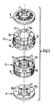
- FIGS 1 to 6 show an internal combustion engine, of the spark-ignition type and whose combustion cycle is two-stroke, to simplify the description below.
- This engine essentially comprises a piston block 1, consisting of two annular pistons 2 and 3 assembled in opposition by their base, of circular cross section, so that these assembled bases constitute a central body 1 a cylindrical and tubular by which the piston block 1 slide axially in the internal bore of a cylindrical casing 4, of circular section, each of the axial ends of which has a radial fixing flange.
- This casing 4 is, at each of its two axial ends, secured to an open axial end of an annular cylinder 5, in the form of a hollow crown.
- annular cylinders 5 are each closed at its axial end opposite to that by which it is secured to the casing, by a bottom 5 a against which is applied one of two circular flanges 6, each having a central opening 7 provided with a bearing 17 to allow the maintenance, the axial passage and the guiding in rotation of a motor shaft 8 or motor output shaft, which crosses coaxially, around its longitudinal axis AA, the casing 4, the two cylinders 5 on the one hand and on the other side of this casing 4, and the two end flanges 6 on either side of the cylinders 5, as well as the piston block 1 formed of the pistons 2 and 3 assembled.
- the monolithic piston block 1 formed by the assembly in opposition of the annular pistons 2 and 3, has a cylindrical and tubular central body 1 a which is pierced, in its middle part, with eight radial guide holes 18, grouped in four pairs of holes which are regularly distributed in circumferential direction around the longitudinal axis of the tubular piston block 1, that is to say which are positioned at 90 ° from each other, the two holes 18 of each pair being further axially spaced one of 1 other, parallel to each other in the same radial plane of the piston block 1.
- each annular piston 2 and 3 comprises a double axial skirt 2 a, 3 a, consisting of two coaxial annular rings, one of which, in an external radial position , is an outer or peripheral ring 9 which is radially spaced from the other, in the internal radial position or internal ring.
- This internal ring essentially consists of a flat ring 10 disposed radially and coaxially, and secured to the corresponding side of the central body 1 a of the piston block 1 by a plurality of axial columns 10 a , and the flat ring 10 is pierced with 11 has axial holes, regularly distributed over its surface in the circumferential direction, and with which are associated valves 11.
- valves 11 are leaf-spring valves which are fixed on the face of the flat ring 10 which faces the body central 1 a of the piston block, and which are prestressed in the closed position of the orifices 11 has drilled in the flat ring 10 of the internal crown, so that the latter can act as an intake pump, ensuring the supply of a cylinder 5 in a combustible mixture, as explained below.
- the outer ring 9 of the double axial skirt 2 a or 3 a of the piston 2 or 3 is shaped as the actual piston head, which is engaged so as to slide axially with sealing in both directions in one of the cylinders annular and hollow 5 (see FIGS. 2 and 5), in which an annular combustion chamber 12 is delimited between the corresponding bottom 5 a of the cylinder 5 and this external radial crown 9.
- the internal radial wall 13 of each cylinder 5 is pierced with intake holes 14, which open into the corresponding combustion chamber 12, when the external radial crown 9 or piston head proper is practically in its bottom dead center position (PMB), that is to say when it is moved axially as far as possible from the bottom 5 a of the corresponding cylinder 5.
- PMB bottom dead center position
- each annular cylinder 5 is pierced with holes 16 which open to the outside of the corresponding cylinder 5 to allow the escape of combustion gases.
- the exhaust holes 16 are grouped in sets of three holes arranged side by side in circumferential direction, these sets of three holes being themselves regularly distributed in this same circumferential direction.
- the two annular cylinders 5 are mounted in opposition, on either side of the housing 4, and being open one towards the other, in such a way that the external radial crown 9 of the double axial skirt 2 a or 3 a of each piston 2 or 3 can move axially in the combustion chamber 12 of the corresponding cylinder 5, the two cylinders 5 being separated from each other with a spacing which corresponds to the axial length of the casing 4.
- the shaft 8 has, at mid-length, a central part 19 which is swollen, of cylindrical shape of circular section, with a larger diameter than the adjacent axial parts of the shaft 8
- a central part 19 In the external lateral face of this central part 19 are formed two grooves 20, of square cross section, which are sinusoidal and peripheral grooves, closing on themselves, or even continuous and endless grooves, and these grooves 20 each form four regular undulations in the longitudinal direction of the shaft 8, and on its periphery, that is to say undulations of the same axial amplitude.
- the housing 4 has four slots 21 drilled radially and extending in the longitudinal direction so as to open into the internal cylindrical bore of the housing 4. These slots 21 are regularly distributed in the circumferential direction around the longitudinal axis of the casing 4, so that they are separated from each other by an angle of 90 °, in order to coincide each with one of the four pairs of guide holes 18 formed radially in the central body 1 a tubular of the piston block 1 shown in Figure 2.
- each of the fingers 22 is thus housed radially through the casing 4 and the piston block 1, so that its internal radial end is housed respectively in one of the two grooves 20 wavy in phase and offset axially along the shaft 8 with the same spacing as that which separates the two radial holes 18 from a pair of holes centered in the same radial plane of the central body 1 a .
- Each of the four pairs of radial fingers 22 is held so that the internal radial end of each of the two corresponding fingers 22 is engaged in that of the two grooves 20 which occupies the corresponding axial position on the central part 19 of the shaft 8, by means of one of four identical cages 23, fixed on the outer part of the casing 4, and each around one of the four slots 21, and each cage 23 contains two ball bearings (not shown) in order to improve the displacement, in the corresponding lumen 21 of the casing 4, of the external radial ends of the two fingers 22 projecting in this lumen 21.
- each of the fingers 22 is divided, substantially at mid-length, into two parts 22 a and 22 b , which allows the internal radial end of the internal radial part 22 a to roll in the corresponding groove 20 of the shaft 8, and at the external radial end of the corresponding external radial part 22 b , to rotate and roll in the cage 23 and in the slot 21 independently of one another, and in particular in the opposite direction.
- each flange 6 and each cylinder 5 have an annular shape and delimit a central opening for the passage of the drive shaft 8, and eight holes 24, equidistant in circumferential direction, are drilled in coincidence and in the axial direction through the flange 6 and the bottom 5 a of the adjacent cylinder, so as to open into the annular combustion chamber 12, to receive spark plugs which will be activated by a common or individual ignition device, not shown .
- the fuel mixture is supplied to the engine assembly by a supply system comprising a supply or intake manifold 25, which extends parallel to the shaft 8 but outside the casing 4, and which itself receives the fuel mixture coming from a carburetor (not shown) by a radial inlet opening 26.
- This inlet manifold 25, longitudinal, has its two ends connected perpendicularly by substantially radial conduits 25 a to two annular end tubes 27 which are applied coaxially against the external axial faces of the two flanges 6.
- each of the two annular tubes 27 is open on the side of the flange 6 corresponding, opposite orifices axial longitudinal 28 formed through the corresponding flange 6, and regularly distributed in circumferential direction, radially inside the spark plug holes 24.
- Each valve 29 can thus be moved axially towards the central body 1a of the piston block 1, so that the valve head is spaced from the corresponding seat machined in the inner axial face of the flange 6 corresponding to let in the combustible mixture in a waiting chamber 30 which is an annular chamber delimited radially between the internal radial wall 13 of the corresponding annular cylinder 5 and an axial sleeve 35, supported coaxially around the shaft 8 by the corresponding flange 6, and extending axially substantially up to the bulged part 19 of the shaft 8, and so that the central body 1 has the piston block 1 slides with sealing around this sleeve 35.
- the internal crown of the corresponding double axial skirt and which is formed by the flat ring 10 and its columns 10 a connecting to the central body 1 a , is also slidably mounted axially in this waiting chamber 30, which is subdivided into two x parts, including an upstream part 30 a , adjacent to the flange 6 and the corresponding valves 29, and of which the other part is a downstream part 30 b , adjacent to the central body 1 a .
- These two parts 30 a and 30 b are separated from each other by the flat ring 10, which slides with sealing on the one hand against the internal radial wall 13 of the corresponding annular cylinder 5 and on the other hand against the sleeve 35 delimiting this chamber 30.
- the internal crown formed of the flat ring 10 with its axial passages 11 a and its valves 11, is secured by the columns 10 a to the central body 1 a , and forms with the waiting chamber 30 a pump admission of fuel mixture into the corresponding annular combustion chamber 12, operating as follows: at start-up, during the first axial strokes of the piston block 1 in the casing 4 and the two cylinders 5, the filling of the combustion chambers 12 is imperfect, but a balance is established very quickly, and the filling becomes normal.
- this piston 2 moves towards its bottom dead center (PMB), that is to say it moves away from the bottom 5 a of the cylinder 5 in which slide the corresponding 9 piston head, which causes the admission of the combustible mixture in the upstream part 30a of the holding chamber 30.
- PMB bottom dead center
- This introduction of combustible mixture into this combustion chamber 12 drives out the gases previously burned in this chamber through the holes d 'exhaust 16 leading to peripheral tubes 31 connected to an exhaust manifold 32.
- the corresponding inner ring and its flat ring 10 undergo the same axial translation, which has for effect of compressing the upstream part 30 a of the chamber 30, while the downstream part 30 b is dilated.
- the intake pump constituted by the cooperation of the flat ring 10 of the inner ring of the double axial skirt of each piston 2 or 3, with the corresponding waiting chamber 30, operates as a fuel mixture suction pump in the upstream part 30 a this chamber and discharge of the combustible mixture of the downstream portion 30 b of the chamber inwardly of the corresponding 12 annular combustion chamber, after transfer of the upstream portion 30a to the downstream portion 30b.
- the intake pumps thus produced are therefore subjected to the same alternating axial movements as the pistons, which are the driving elements for the pumps and drive them, but which can only deliver their driving force because of the supply of fuel mixture provided by these pumps.
- Each outer ring 9, forming the actual piston head, of the corresponding piston 2 or 3 has internal and external segments 34 which allow good sealing against the inner and opposite cylindrical faces of the outer 15 and inner 13 radial walls defining the annular combustion chamber 12.
- the four pairs of radial fingers 22 transform the translational movement of the piston block 1 into a rotary movement of the motor shaft 8, by the fact that any axial movement of the piston block 1 causes the fingers 22 in a translational movement of the same amplitude, and these fingers 22 roll by their internal radial end in the corrugated grooves 20 of the shaft 8, causing a rotary movement of the latter.
- the axial spacing of the two holes 18 of a pair of holes in a particular angular position at the periphery of the central body 1 a corresponds to the spacing of the two corrugated grooves 20 of the central part 19 of the 'shaft 8 shown in Figure 4, and the height or amplitude of a ripple is substantially equal to the axial stroke of the piston 1.
- the radial fingers 22 can rotate on themselves in the holes 18 of the block piston 1 by means of needle bearings 33 mounted in each of these holes 18, as shown in FIGS. 5 and 6.
- the movement transformation mechanism is reversed, insofar as radial fingers are housed and retained in the bulged central part 19 of the motor shaft 8, so that one at less of their ends, in the external radial position, is engaged and can roll in one of the sinusoidal grooves formed in the cylindrical face in the internal radial position on the annular piston block 1, and in particular on its central body 1 a .
- each of the flanges 6 is necessary to ensure the admission of oxidant gas and / or fuel to the annular combustion chambers 12, as well as for the mounting and guiding of the rotary shaft. 8.
- these flanges 6 are only pierced with spark plug receiving holes if the engine is of the spark-ignition type. If this engine is a diesel engine, there is no need to drill the flanges 6 and the bottoms 5 has cylinders 5 for the spark plug housing.
- the internal combustion engine according to the invention finds more particularly its application for the equipment of airplanes and other types of aerodynes, because of the facility which it presents to adapt the rotation speed of the shaft. to the nature of the use, but, of course, such an engine can be used to equip marine or land vehicles.
Landscapes
- Engineering & Computer Science (AREA)
- Mechanical Engineering (AREA)
- General Engineering & Computer Science (AREA)
- Chemical & Material Sciences (AREA)
- Combustion & Propulsion (AREA)
- Cylinder Crankcases Of Internal Combustion Engines (AREA)
- Combustion Methods Of Internal-Combustion Engines (AREA)
Claims (11)
Priority Applications (1)
| Application Number | Priority Date | Filing Date | Title |
|---|---|---|---|
| DE8888400391T DE3868261D1 (de) | 1986-09-02 | 1988-02-19 | Zentralachsige brennkraftmaschine mit einander gegenueberliegenden und fest verbundenen ringfoermigen kolben. |
Applications Claiming Priority (2)
| Application Number | Priority Date | Filing Date | Title |
|---|---|---|---|
| FR8612628A FR2603338B1 (fr) | 1986-09-02 | 1986-09-02 | Moteur a combustion interne a piston annulaire et arbre central |
| CA000560193A CA1320878C (fr) | 1986-09-02 | 1988-03-01 | Moteur a combustion interne a pistons annulaires, en opposition et solidaires, et a arbre central |
Publications (2)
| Publication Number | Publication Date |
|---|---|
| EP0328835A1 EP0328835A1 (de) | 1989-08-23 |
| EP0328835B1 true EP0328835B1 (de) | 1992-01-29 |
Family
ID=25671745
Family Applications (1)
| Application Number | Title | Priority Date | Filing Date |
|---|---|---|---|
| EP88400391A Expired - Lifetime EP0328835B1 (de) | 1986-09-02 | 1988-02-19 | Zentralachsige Brennkraftmaschine mit einander gegenüberliegenden und fest verbundenen ringförmigen Kolben |
Country Status (5)
| Country | Link |
|---|---|
| US (1) | US4887558A (de) |
| EP (1) | EP0328835B1 (de) |
| CA (1) | CA1320878C (de) |
| DE (1) | DE3868261D1 (de) |
| FR (1) | FR2603338B1 (de) |
Families Citing this family (11)
| Publication number | Priority date | Publication date | Assignee | Title |
|---|---|---|---|---|
| US4974556A (en) * | 1989-12-07 | 1990-12-04 | Royse Enterprises, Inc. | Internal combustion engine |
| US5228415A (en) * | 1991-06-18 | 1993-07-20 | Williams Thomas H | Engines featuring modified dwell |
| US5743220A (en) | 1996-07-29 | 1998-04-28 | Guarner-Lans; Enrique Eduardo | Internal combustion engine with central chamber |
| US5749337A (en) * | 1997-03-31 | 1998-05-12 | Palatov; Dennis | Barrel type internal combustion engine |
| ITLE20000014A1 (it) * | 2000-06-29 | 2001-12-31 | Cesare Bortone | Motore endotermico alternativo con pistoni anulari e innovativo sistema di parzializzazione del carico per un particolare ciclo di compustio |
| US20060157017A1 (en) * | 2001-06-28 | 2006-07-20 | Cesare Bortone | Exhaust valve and intake system |
| US7124718B2 (en) * | 2003-01-23 | 2006-10-24 | Jorge Artola | Multi-chamber internal combustion engine |
| US20040149122A1 (en) * | 2003-01-30 | 2004-08-05 | Vaughan Billy S. | Crankless internal combustion engine |
| FR2928693A1 (fr) * | 2008-03-17 | 2009-09-18 | Antar Daouk | Moteur a combustion interne |
| RU2011108524A (ru) * | 2008-07-25 | 2012-08-27 | ББ Мотор Корп, ЛЛК (US) | Гидравлический двигатель с неограниченным углом поворота вала |
| US10415500B2 (en) * | 2015-09-14 | 2019-09-17 | Vianney Rabhi | Double-acting pressure reducing cylinder with adaptive support |
Family Cites Families (16)
| Publication number | Priority date | Publication date | Assignee | Title |
|---|---|---|---|---|
| DE290893C (de) * | ||||
| GB191311027A (en) * | 1913-05-09 | 1914-05-11 | Franz Miller | Improvements in Internal Combustion or other Fluid Pressure Motors. |
| FR479689A (fr) * | 1914-09-16 | 1916-04-27 | Franz Miller | Moteur de grande puissance avec pistons annulaires dont le mouvement alternatif est transformé en mouvement rotatoire de l'arbre à l'aide de guides ondulés |
| US1197591A (en) * | 1915-09-30 | 1916-09-12 | Samuel G Bargery | Internal-combustion engine. |
| US1613136A (en) * | 1925-06-11 | 1927-01-04 | Schuyler Schieffelin | Internal-combustion motor. |
| US1745821A (en) * | 1927-03-18 | 1930-02-04 | Gribojedoff Nicolai Von | Internal-combustion engine |
| DE501342C (de) * | 1928-10-09 | 1930-07-01 | Julius Seifert | Kurbelwellenloser Zweitakt-Zwillingsmotor |
| DE2065512A1 (de) * | 1970-07-08 | 1974-05-02 | Patrick Joseph Walls | Brennkraftmaschine |
| CH553918A (fr) * | 1971-09-08 | 1974-09-13 | Milisavljevic Milorad | Moteur thermique. |
| US3786790A (en) * | 1972-08-03 | 1974-01-22 | J Plevyak | Double-chambered reciprocatable double-action-piston internal combustion engine |
| FR2244077A1 (en) * | 1973-09-17 | 1975-04-11 | Etienne Charles | Independent lubricating device for two-stroke engine - axial casing projection reduces dead piston volume |
| US3943859A (en) * | 1974-11-25 | 1976-03-16 | Philip Boone | Shelf attachment |
| US4090478A (en) * | 1976-07-26 | 1978-05-23 | Trimble James A | Multiple cylinder sinusoidal engine |
| FR2439297A1 (fr) * | 1978-10-18 | 1980-05-16 | Etienne Charles | Machines a pistons sans embiellage |
| US4453504A (en) * | 1979-04-09 | 1984-06-12 | Germicidal Electronics, Inc. | Single piston, double chambered reciprocal internal combustion engine |
| US4462345A (en) * | 1981-07-13 | 1984-07-31 | Pulsar Corporation | Energy transfer device utilizing driveshaft having continuously variable inclined track |
-
1986
- 1986-09-02 FR FR8612628A patent/FR2603338B1/fr not_active Expired - Lifetime
-
1988
- 1988-02-19 DE DE8888400391T patent/DE3868261D1/de not_active Expired - Fee Related
- 1988-02-19 EP EP88400391A patent/EP0328835B1/de not_active Expired - Lifetime
- 1988-02-23 US US07/159,266 patent/US4887558A/en not_active Expired - Fee Related
- 1988-03-01 CA CA000560193A patent/CA1320878C/fr not_active Expired - Fee Related
Also Published As
| Publication number | Publication date |
|---|---|
| FR2603338B1 (fr) | 1990-12-21 |
| CA1320878C (fr) | 1993-08-03 |
| DE3868261D1 (de) | 1992-03-12 |
| EP0328835A1 (de) | 1989-08-23 |
| US4887558A (en) | 1989-12-19 |
| FR2603338A1 (fr) | 1988-03-04 |
Similar Documents
| Publication | Publication Date | Title |
|---|---|---|
| EP0328835B1 (de) | Zentralachsige Brennkraftmaschine mit einander gegenüberliegenden und fest verbundenen ringförmigen Kolben | |
| EP0034085B1 (de) | Gaserzeuger mit positiver Verdrängung | |
| EP0145626A1 (de) | Wärmemaschine mit rotierenden, oszillierenden Kolben und mit kugelförmiger Kammer | |
| EP2279332B1 (de) | Verbrennungsmotor | |
| EP0750719B1 (de) | Brennkraftmaschine mit gaswechseldrehschieberanordnungen | |
| EP0130171B1 (de) | Drehkolben-Brennkraftmaschine | |
| FR2540933A1 (fr) | Moteur a combustion interne a deux pistons opposes | |
| FR2598746A1 (fr) | Machine a piston rotatif. | |
| EP0250960A2 (de) | Brennkraftmaschine | |
| EP0069039B1 (de) | Aufgeladene Brennkraftmaschine | |
| FR2664329A1 (fr) | Turbine a reaction a compresseur. | |
| FR2739659A1 (fr) | Moteur a 3 temps egaux, dont le mouvement rectiligne des bielles permet d'obturer le bas des cylindres et d'utiliser le volume cree en chambre d'admission | |
| EP0799978A2 (de) | Zweitaktbrennkraftmaschine mit Kreuzkopf und eine röhrenförmige Drehschieberventileinrichtung | |
| FR2757568A1 (fr) | Moteur thermique 3 temps a 4 ou 6 cylindres opposes 2 a 2 avec un vilebrequin contrarotatif excentre et une distribution automatique | |
| FR2531139A1 (fr) | Dispositif de controle d'un circuit de gaz d'une chambre de combustion | |
| FR2807466A1 (fr) | Moteur thermique avec ensembles piston/cylindre a deplacement relatifs autour d'un axe | |
| FR3028563A1 (fr) | Piston alternatif et contenant faisant moteur thermique, pneumatique, hybride et recuperateur d'energie pneumatique | |
| WO2021084176A1 (fr) | Moteur à combustion interne | |
| FR2925571A1 (fr) | Machine a pistons rotatifs a battement controle | |
| FR2466609A1 (fr) | Machine rotative | |
| FR2571779A1 (fr) | Capsulisme a palettes commandees sur roulements pour moteurs et pompes | |
| BE823161A (fr) | Moteur rotatif | |
| FR2742478A1 (fr) | Machine d'entrainement rotatif a chambres annulaires, du type moteur thermique ou pompe | |
| WO2017194844A1 (fr) | Piston alternatif et contenant faisant moteur thermique, pneumatique, hybride et récupérateur d'énergie pneumatique. | |
| FR2760787A1 (fr) | Machine tournante a pistons tangentiels utilisable comme moteur a combustion interne, moteur a fluide, pompe, compresseur |
Legal Events
| Date | Code | Title | Description |
|---|---|---|---|
| PUAI | Public reference made under article 153(3) epc to a published international application that has entered the european phase |
Free format text: ORIGINAL CODE: 0009012 |
|
| AK | Designated contracting states |
Kind code of ref document: A1 Designated state(s): DE ES GB IT NL SE |
|
| 17P | Request for examination filed |
Effective date: 19890314 |
|
| 17Q | First examination report despatched |
Effective date: 19910125 |
|
| GRAA | (expected) grant |
Free format text: ORIGINAL CODE: 0009210 |
|
| AK | Designated contracting states |
Kind code of ref document: B1 Designated state(s): DE ES GB IT NL SE |
|
| PG25 | Lapsed in a contracting state [announced via postgrant information from national office to epo] |
Ref country code: IT Free format text: LAPSE BECAUSE OF FAILURE TO SUBMIT A TRANSLATION OF THE DESCRIPTION OR TO PAY THE FEE WITHIN THE PRE;WARNING: LAPSES OF ITALIAN PATENTS WITH EFFECTIVE DATE BEFORE 2007 MAY HAVE OCCURRED AT ANY TIME BEFORE 2007. THE CORRECT EFFECTIVE DATE MAY BE DIFFERENT FROM THE ONE RECORDED.SCRIBED TIME-LIMIT Effective date: 19920129 Ref country code: SE Effective date: 19920129 Ref country code: NL Effective date: 19920129 Ref country code: ES Free format text: THE PATENT HAS BEEN ANNULLED BY A DECISION OF A NATIONAL AUTHORITY Effective date: 19920129 |
|
| REF | Corresponds to: |
Ref document number: 3868261 Country of ref document: DE Date of ref document: 19920312 |
|
| GBT | Gb: translation of ep patent filed (gb section 77(6)(a)/1977) | ||
| NLV1 | Nl: lapsed or annulled due to failure to fulfill the requirements of art. 29p and 29m of the patents act | ||
| PLBE | No opposition filed within time limit |
Free format text: ORIGINAL CODE: 0009261 |
|
| STAA | Information on the status of an ep patent application or granted ep patent |
Free format text: STATUS: NO OPPOSITION FILED WITHIN TIME LIMIT |
|
| 26N | No opposition filed | ||
| PGFP | Annual fee paid to national office [announced via postgrant information from national office to epo] |
Ref country code: GB Payment date: 19970210 Year of fee payment: 10 |
|
| PGFP | Annual fee paid to national office [announced via postgrant information from national office to epo] |
Ref country code: DE Payment date: 19970424 Year of fee payment: 10 |
|
| PG25 | Lapsed in a contracting state [announced via postgrant information from national office to epo] |
Ref country code: GB Free format text: LAPSE BECAUSE OF NON-PAYMENT OF DUE FEES Effective date: 19980219 |
|
| GBPC | Gb: european patent ceased through non-payment of renewal fee |
Effective date: 19980219 |
|
| PG25 | Lapsed in a contracting state [announced via postgrant information from national office to epo] |
Ref country code: DE Free format text: LAPSE BECAUSE OF NON-PAYMENT OF DUE FEES Effective date: 19981103 |