EP0250960B1 - Internal-combustion engine - Google Patents
Internal-combustion engine Download PDFInfo
- Publication number
- EP0250960B1 EP0250960B1 EP87108372A EP87108372A EP0250960B1 EP 0250960 B1 EP0250960 B1 EP 0250960B1 EP 87108372 A EP87108372 A EP 87108372A EP 87108372 A EP87108372 A EP 87108372A EP 0250960 B1 EP0250960 B1 EP 0250960B1
- Authority
- EP
- European Patent Office
- Prior art keywords
- valve
- chamber
- variable volume
- fact
- exhaust
- Prior art date
- Legal status (The legal status is an assumption and is not a legal conclusion. Google has not performed a legal analysis and makes no representation as to the accuracy of the status listed.)
- Expired - Lifetime
Links
Images


Classifications
-
- F—MECHANICAL ENGINEERING; LIGHTING; HEATING; WEAPONS; BLASTING
- F02—COMBUSTION ENGINES; HOT-GAS OR COMBUSTION-PRODUCT ENGINE PLANTS
- F02G—HOT GAS OR COMBUSTION-PRODUCT POSITIVE-DISPLACEMENT ENGINE PLANTS; USE OF WASTE HEAT OF COMBUSTION ENGINES; NOT OTHERWISE PROVIDED FOR
- F02G1/00—Hot gas positive-displacement engine plants
- F02G1/02—Hot gas positive-displacement engine plants of open-cycle type
-
- F—MECHANICAL ENGINEERING; LIGHTING; HEATING; WEAPONS; BLASTING
- F02—COMBUSTION ENGINES; HOT-GAS OR COMBUSTION-PRODUCT ENGINE PLANTS
- F02B—INTERNAL-COMBUSTION PISTON ENGINES; COMBUSTION ENGINES IN GENERAL
- F02B19/00—Engines characterised by precombustion chambers
- F02B19/02—Engines characterised by precombustion chambers the chamber being periodically isolated from its cylinder
-
- F—MECHANICAL ENGINEERING; LIGHTING; HEATING; WEAPONS; BLASTING
- F02—COMBUSTION ENGINES; HOT-GAS OR COMBUSTION-PRODUCT ENGINE PLANTS
- F02B—INTERNAL-COMBUSTION PISTON ENGINES; COMBUSTION ENGINES IN GENERAL
- F02B75/00—Other engines
- F02B75/02—Engines characterised by their cycles, e.g. six-stroke
- F02B75/021—Engines characterised by their cycles, e.g. six-stroke having six or more strokes per cycle
-
- F—MECHANICAL ENGINEERING; LIGHTING; HEATING; WEAPONS; BLASTING
- F02—COMBUSTION ENGINES; HOT-GAS OR COMBUSTION-PRODUCT ENGINE PLANTS
- F02G—HOT GAS OR COMBUSTION-PRODUCT POSITIVE-DISPLACEMENT ENGINE PLANTS; USE OF WASTE HEAT OF COMBUSTION ENGINES; NOT OTHERWISE PROVIDED FOR
- F02G1/00—Hot gas positive-displacement engine plants
-
- F—MECHANICAL ENGINEERING; LIGHTING; HEATING; WEAPONS; BLASTING
- F02—COMBUSTION ENGINES; HOT-GAS OR COMBUSTION-PRODUCT ENGINE PLANTS
- F02B—INTERNAL-COMBUSTION PISTON ENGINES; COMBUSTION ENGINES IN GENERAL
- F02B75/00—Other engines
- F02B75/02—Engines characterised by their cycles, e.g. six-stroke
- F02B2075/022—Engines characterised by their cycles, e.g. six-stroke having less than six strokes per cycle
- F02B2075/027—Engines characterised by their cycles, e.g. six-stroke having less than six strokes per cycle four
-
- F—MECHANICAL ENGINEERING; LIGHTING; HEATING; WEAPONS; BLASTING
- F02—COMBUSTION ENGINES; HOT-GAS OR COMBUSTION-PRODUCT ENGINE PLANTS
- F02B—INTERNAL-COMBUSTION PISTON ENGINES; COMBUSTION ENGINES IN GENERAL
- F02B2275/00—Other engines, components or details, not provided for in other groups of this subclass
- F02B2275/18—DOHC [Double overhead camshaft]
-
- F—MECHANICAL ENGINEERING; LIGHTING; HEATING; WEAPONS; BLASTING
- F02—COMBUSTION ENGINES; HOT-GAS OR COMBUSTION-PRODUCT ENGINE PLANTS
- F02B—INTERNAL-COMBUSTION PISTON ENGINES; COMBUSTION ENGINES IN GENERAL
- F02B3/00—Engines characterised by air compression and subsequent fuel addition
- F02B3/06—Engines characterised by air compression and subsequent fuel addition with compression ignition
-
- F—MECHANICAL ENGINEERING; LIGHTING; HEATING; WEAPONS; BLASTING
- F02—COMBUSTION ENGINES; HOT-GAS OR COMBUSTION-PRODUCT ENGINE PLANTS
- F02G—HOT GAS OR COMBUSTION-PRODUCT POSITIVE-DISPLACEMENT ENGINE PLANTS; USE OF WASTE HEAT OF COMBUSTION ENGINES; NOT OTHERWISE PROVIDED FOR
- F02G2258/00—Materials used
- F02G2258/10—Materials used ceramic
-
- F—MECHANICAL ENGINEERING; LIGHTING; HEATING; WEAPONS; BLASTING
- F02—COMBUSTION ENGINES; HOT-GAS OR COMBUSTION-PRODUCT ENGINE PLANTS
- F02G—HOT GAS OR COMBUSTION-PRODUCT POSITIVE-DISPLACEMENT ENGINE PLANTS; USE OF WASTE HEAT OF COMBUSTION ENGINES; NOT OTHERWISE PROVIDED FOR
- F02G2270/00—Constructional features
- F02G2270/50—Crosshead guiding pistons
-
- Y—GENERAL TAGGING OF NEW TECHNOLOGICAL DEVELOPMENTS; GENERAL TAGGING OF CROSS-SECTIONAL TECHNOLOGIES SPANNING OVER SEVERAL SECTIONS OF THE IPC; TECHNICAL SUBJECTS COVERED BY FORMER USPC CROSS-REFERENCE ART COLLECTIONS [XRACs] AND DIGESTS
- Y02—TECHNOLOGIES OR APPLICATIONS FOR MITIGATION OR ADAPTATION AGAINST CLIMATE CHANGE
- Y02T—CLIMATE CHANGE MITIGATION TECHNOLOGIES RELATED TO TRANSPORTATION
- Y02T10/00—Road transport of goods or passengers
- Y02T10/10—Internal combustion engine [ICE] based vehicles
- Y02T10/12—Improving ICE efficiencies
Definitions
- the present invention relates to internal combustion engines whose operating cycle comprises six times or more as described for example in US patent 4,513,568 and published European patent application No. 0.104.541 or in the publication of " Society of Automotive Engineers, Inc “titled” The Bajulaz Cycle: A Two-Chamber Internal Combustion Engin with Increased Thermal Efficiency "in the SAE Technical Paper Series No. 860534 of February 1986.
- the present invention relates to an internal combustion engine of the aforementioned type tending to overcome the drawbacks listed above, by the absence of rotary or angular movements between parts to form a sealed assembly.
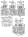
- Figure 1 is a cross section of the engine passing through the axis of a cylinder.
- Figure 2 is a section along line II-II of Figure 1.
- Figures 3 to 8 are cross sections of the engine, similar to Figure 1 but on a smaller scale, illustrating each of the six times of its operating cycle.
- Figures 9 to 11 are partial sections of a second embodiment of the engine respectively corresponding to the intake, the expansion of hot air and the exhaust respectively.
- Figure 12 is a partial top view of a third embodiment of the engine.
- FIG. 13 is a partial sectional view of the embodiment illustrated in FIG. 12.
- the internal combustion engine illustrated in FIGS. 1 to 8 comprises an engine block 1, provided with a conventional cooling circuit 2, the lower end of which is closed off by a casing 3.
- the engine block 1 comprises at least one bore constituting a cylinder 4 in which moves in a known manner, a piston 5 articulated on a connecting rod 6 by an axis 7.
- This piston 5 is provided with conventional sealing segments 8.
- the combustion chamber of which is made up of part of the variable volume chamber, in the present case the volume of this variable volume chamber 16 is substantially equal to zero when the piston 5 is in the high position.
- the lower end of the connecting rod 6 is journalled on a crankpin 9 of a crankshaft 10 pivoted in bearings of the engine block 1, this in a conventional manner.
- a cylinder head comprising a lower body 11 and an upper body 12 is fixed on the upper part of the engine block 1 in a known manner. Finally, the upper part of the cylinder head is closed by a camshaft cover 13.
- a kinematic link connects the crankshaft 10 to the camshafts 14,15 in order to drive the latter at an angular speed three times lower than that of the crankshaft 10.
- the cylinder 4, the piston 5 and the lower face of the lower body 11 of the cylinder head define a variable volume chamber 16 whose upper surface, formed by the lower face of the lower body 11 of the cylinder head, has two holes 17,18 provided with valve seats.
- the orifice 17 places the variable volume chamber 16 in communication with a combustion chamber 19, formed in the cylinder head and delimited by a partition made of a material allowing rapid heat transfer.
- the orifice 18 puts the variable volume chamber 16 into communication with a preheating chamber 20 formed in the cylinder head and almost completely surrounding the combustion chamber 19.
- the walls of this preheating chamber can be made of an insulating material, for example in ceramic.
- the upper body 12 of the cylinder head comprises an exhaust duct 21 communicating with the combustion chamber 19 through an orifice 22 opening into a skirt 23 coaxial with the opening 17 connecting the combustion chamber 19 to the variable volume chamber 16.
- This skirt 23 has one or more openings 24 formed in its circumferential wall and communicating with the combustion chamber 19.
- An injector 25 allows fuel to be injected into the combustion chamber 19 at the desired time depending on the operating cycle.
- a valve 27, coaxial with the opening 17 cooperates with the seat of this opening to separate the variable-volume chamber 16 from the combustion chamber 19, the rod 28 of which extends through the combustion chamber 19, from the skirt 23 and is guided in the upper body 12 of the cylinder head.
- the upper end of the rod 28 is secured to a pusher 30 which cooperates with a cam 31 secured to the camshaft 14.
- a spring 32 bearing on the upper body 12 of the cylinder head and the pusher 30 tends to hold the valve 27 against its seat in the closed position.
- a piston 33 secured to the valve stem 28 slides in leaktight manner in the skirt 23 and the opening 22 and constitutes the movable part of a closure device of which the skirt 23 constitutes the fixed part. By a linear movement, the piston 33 respectively closes the openings 24 so as to close respectively open the communication between the combustion chamber 19 and the exhaust manifold 21.
- the cam 31 comprises several lifts, one of great height 34 and two 35.36 of lower height.
- the upper body 12 of the cylinder head also comprises an intake duct 40 communicating with the preheating chamber 20 through an orifice 41 opening into a skirt 42, coaxial with the opening 18 connecting the preheating chamber 20 to the chamber variable volume 16, and constituting the fixed member of a closure device.
- This skirt 42 includes one or more openings 43 communicating with the preheating chamber 20.
- a valve 44 coaxial with the opening 18 cooperates with a seat of this opening to separate the variable-volume chamber 16 from the preheating chamber 20, a valve whose rod 45 extends through the preheating chamber 20, the skirt 42 and is guided in the upper body 12 of the cylinder head.
- the upper end of the rod 45 is secured to a pusher 46 which cooperates with a cam 47 secured to the camshaft 15.
- a spring 48 is supported on the upper body 12 of the cylinder head and the pusher 46 to maintain the valve 44 against its seat in the closed position.
- a piston 49 slides in leaktight fashion in the skirt 42 and the opening 41 and constitutes the movable part of a closure device, the skirt 42 of which constitutes the fixed part. By a linear movement, the piston 49 respectively closes the openings 43 in a manner to close respectively to open the communication between the preheating chamber 20 and the intake manifold 40.
- Cam 47 has two small lifts 50.51 and a large lift 52.
- combustion 19 and preheating chambers 20 are located immediately above the variable volume chamber 16 and the latter cannot be connected to the exhaust manifolds 21 or intake 40 respectively. 'through the combustion chambers 19 and preheating respectively 20. This ensures, during operation, a complete sweep of the combustion chambers 19 and preheating 20 allowing complete evacuation of the gases therein and gives better engine efficiency.
- valves 27,44, their stems 28,45 and the pistons 33,49 as well as skirts 23,42 or the cylinder head itself can be made of ceramic.
- FIGS 3 to 8 schematically illustrate the six times of the engine operating cycle described.
- FIG. 3 represents the admission of air into the variable volume chamber 16.
- the large lift 52 of the cam 47 moves the valve 44 and its rod 45 fully, therefore the piston 49 also, and the variable volume chamber 16 , whose volume increases, is connected, via the preheating chamber 20 with the intake manifold 40.
- the valve 27 is on its seat and the closure device 23,24,33 is closed; the combustion chamber 19 filled with preheated compressed air (FIG. 8) is isolated and a fuel is injected into it by the injector 25, and the mixture is ignited.
- preheated compressed air FIG. 8
- the piston 5 arrives at the end of the lower stroke (FIG. 4) the pusher 46 cooperates with the lift 51 of low height so that the opening 18 is still open but the closure device 42, 43, 49 is closed. During the upward stroke of the piston 5 the air is discharged and compressed in the preheating chamber 20 which is now separated from the intake manifold 40.
- the piston 5 arrives at the end of the upper stroke (FIG. 5), the valve 44 and the closure device 42, 43, 49 are closed while the pusher 30 is moved by the small lift 35 causing the valve 27 to open, the closure device 23, 24, 33 remaining closed.
- the combustion gases escaping from the combustion chamber push the piston 5 down. It is the first active time transmitting power to crankshaft 10.
- the piston 5 again arrives in the low position (FIG. 6) the pusher 30 cooperates with the large lift 34 and the variable-volume chamber 16 is connected to the exhaust pipe 21 via the combustion chamber 19. During the upward stroke of the piston 5 the combustion gases are evacuated.
- the piston 5 again arrives in the high position (FIG. 7), the valve 27 and the closure device 23, 24, 33 are closed while the pusher 46 cooperates with the lifting of low height 51 causing the valve to open. 44 but maintaining the closed position of the shutter device 42,43,49.
- the air contained in the preheating chamber 20 which has been heated by heat exchange through the wall separating it from the combustion chamber 19 and whose pressure has thus increased escapes into the variable volume chamber 16 causing the descent of piston 5. It is the second active time, producer of power, of the cycle.
- the air or mixture flow crosses twice the opening 17 of the variable volume chamber 16 towards the combustion chamber 19 and once in the opposite direction from the combustion chamber 19 towards the variable volume chamber 16.
- the engine could comprise two combustion chambers each comprising a valve and a shut-off device as described above.
- the operating cycle comprises eight times, the camshafts rotate four times slower than the crankshaft 10.
- variable volume chamber 16 admission into and exhaust from the variable volume chamber 16 is effected by means of valves controlled by one or more camshafts as is traditionally done in existing engines.
- closure devices ensuring the opening and closing of the connections between the combustion chamber 19 and the exhaust manifold 21 respectively between the preheating chamber 20 and the intake manifold 40 are also constituted by pistons sliding linearly in back and forth movements, synchronous to those of the valves of which they are integral, in skirts or shirts.
- cams with several lifts offset from each other by approximately 60 ° to 120 °, having two different heights also does not give rise to any particular production problems.
- Figures 9 to 11 illustrate in partial section a second embodiment of the engine described above in which the arrangement of the preheating and combustion chambers in the cylinder head is different and in which the closure devices associated with the valves are also of construction different.
- the cylinder head 50 comprises a preheating chamber 51 occupying practically the entire surface situated above the variable volume chamber 16.
- This preheating chamber contains a combustion chamber 52 housed in this preheating chamber and comprising passages 53 giving passage to the valves and which are therefore aligned on the orifice 57 connecting the preheating chamber 51 respectively the combustion chamber 52 to the variable volume chamber and on the orifice 54 connecting this preheating chamber respectively the combustion 52 at the intake manifold 55 respectively at the exhaust manifold.
- the engine also includes an intake valve 56 cooperating with a seat of the orifice 57 whose rod 64 passes through the passage 53, the orifice 54 and the intake manifold 55 and comprises at its free end a pusher 58 cooperating with a cam 59 with three lifts 60,61 and 62.
- Two lifts 60,61 have the same amplitude while the lift 62 has a greater amplitude than the others as in the case described above.
- This valve tends to be held in the closed position by a spring 63.
- the stem 64 of the valve 56 serves as a guide for a moving part of a closure device which has a tubular part 65 sliding on the valve stem 64 and extends through the wall of the intake manifold 55 as well as a part constituting a cylinder 66 sliding in the orifice 54 of the cylinder head 50, the sealing being ensured by segments.
- the upper part of this cylindrical part has openings 67 giving access to the intake manifold 55 and the lower part of this cylindrical part is open and opens into the preheating chamber, respectively into the combustion chamber.
- the tubular part 65 of this movable part of the closure device has a stop 68 limiting its downward movements.
- a spring 69 bearing between the pusher 58 and this stop 68 tends to move the moving part 65, 66 of the shutter device downward.
- the valve stem 64 also has a second valve 70 cooperating with a seat formed at the open end of the cylinder 66.
- the exhaust valve is similarly provided with a second valve cooperating with an identical closure device sliding in an orifice connecting the combustion chamber 52 to the exhaust manifold (not shown).
- valve 56 When the pusher 58 is actuated by one of the lifts 60 and 61 of low amplitude the valve 56 is moved and opens the orifice 57 bringing the preheating chamber 51 into communication with the variable volume chamber 16. This corresponds to the time of expansion of the preheated air.
- the spring 69 moves the moving part 65, 66 together with the valve stem 64 and this part of the closure device is in abutment against the valve 70 thus preventing any communication between the preheating chamber 51 and the manifold. admission 55.
- valve 56 When the pusher 58 is actuated by the cam 62 of large amplitude, the valve 56 is always open, the stop 68 limits the axial movement of the part 65, 66 of the closure device so that the valve 70 leaves its seat and opens a passage connecting the preheating chamber 51 to the intake manifold 55 ( Figure 11). In this position the variable volume chamber 16 is connected, through the preheating chamber, to the intake manifold.
- valve stem 64 has two valves 56 and 70.
- FIGS. 12 and 13 comprises, in addition to the members described with reference to FIGS. 9 to 11, direct accesses between the variable volume chamber 16 and the intake and exhaust pipes 55 78.
- Each of these connections comprises a channel 71, 72 directly connecting the variable-volume chamber 16 to the intake manifold 55 respectively of exhaust 78 passing in leaktight manner through the preheating 51 and combustion 52 chambers.
- channels 71,72 comprise on the side of the variable volume chamber 16 a valve seat cooperating with a valve 73 integral with a rod 74 and actuated by a second camshaft 75 by means of cam 76 at a lift.
- the variable volume chamber 16 is connected to the exhaust manifolds respectively of the intake via the channels 72, 71 respectively and simultaneously in the manner described in the second form of execution.
- the total passage section is increased causing a faster gas discharge aspiration and with less pressure drops.
- multi-fuel that is to say that they can use all kinds of fuels, several even alternately and indifferently without any setting.
- these fuels which can be used in such engines there may be mentioned, for example, super or unleaded petrol, diesel, various heavy oils, alcohol, kerosene, city gas or natural gas and even powdered fuels.
- Slow-burning fuels can also be used since the total burning time extends over a significant period of time, at least for one third of the complete cycle.
- the combustion chamber remains during the whole cycle at a high temperature and its walls remain permanently in the incandescent state; this greatly facilitates the total combustion of fuels.
Description
La présente invention se rapporte aux moteurs à combustion interne dont le cycle de fonctionnement comporte six temps ou plus tels que décrits par exemple dans le brevet US 4.513.568 et la demande de brevet européen publié No 0.104.541 ou dans la publication de la "Society of Automotive Engineers, Inc" intitulée "The Bajulaz Cycle : A Two-Chamber Internal Combustion Engin with Increased Thermal Efficiency" dans la série SAE Technical Paper Series No. 860534 de février 1986.The present invention relates to internal combustion engines whose operating cycle comprises six times or more as described for example in US patent 4,513,568 and published European patent application No. 0.104.541 or in the publication of " Society of Automotive Engineers, Inc "titled" The Bajulaz Cycle: A Two-Chamber Internal Combustion Engin with Increased Thermal Efficiency "in the SAE Technical Paper Series No. 860534 of February 1986.
Du point de vue pratique ces moteurs présentent principalement l'inconvénient de nécessiter la réalisation d'étanchéité entre des pièces rotatives ou oscillantes angulairement du système de distribution du cycle à six temps ce qui dans certains cas peut présenter des problèmes de friction, de graissage et des difficultés de réalisation pratique.From a practical point of view, these motors mainly have the drawback of requiring sealing between angularly rotating or oscillating parts of the six-stroke cycle distribution system, which in certain cases can present problems of friction, lubrication and difficulties in practical implementation.
La présente invention a pour objet un moteur à combustion interne du type précité tendant à obvier aux inconvénients énumérés ci-dessus, par l'absence de mouvements rotatifs ou angulaires entre des pièces devant former un assemblage étanche.The present invention relates to an internal combustion engine of the aforementioned type tending to overcome the drawbacks listed above, by the absence of rotary or angular movements between parts to form a sealed assembly.
Ce moteur à combustion interne se distingue par les caractéristiques énumérées à la revendication 1.This internal combustion engine is distinguished by the characteristics listed in claim 1.
Le dessin annexé illustre schématiquement et à titre d'exemple différentes formes d'exécution du moteur à combustion interne selon l'invention.The accompanying drawing illustrates schematically and by way of example different embodiments of the combustion engine internal according to the invention.
La figure 1 est une coupe transversale du moteur passant par l'axe d'un cylindre.Figure 1 is a cross section of the engine passing through the axis of a cylinder.
La figure 2 est une coupe suivant la ligne II-II de la figure 1.Figure 2 is a section along line II-II of Figure 1.
Les figures 3 à 8 sont des coupes transversales du moteur, semblables à la figure 1 mais à plus petite échelle, illustrant chacun des six temps de son cycle de fonctionnement.Figures 3 to 8 are cross sections of the engine, similar to Figure 1 but on a smaller scale, illustrating each of the six times of its operating cycle.
Les figures 9 à 11 sont des coupes partielles d'une seconde forme d'exécution du moteur correspondant respectivement à l'admission, l'expansion d'air chaud et à l'échappement respectivement.Figures 9 to 11 are partial sections of a second embodiment of the engine respectively corresponding to the intake, the expansion of hot air and the exhaust respectively.
La figure 12 est une vue partielle de dessus d'une troisième forme d'exécution du moteur.Figure 12 is a partial top view of a third embodiment of the engine.
La figure 13 est une vue en coupe partielle de la forme d'exécution illustrée à la figure 12.FIG. 13 is a partial sectional view of the embodiment illustrated in FIG. 12.
Le moteur à combustion interne illustré aux figures 1 à 8 comporte un bloc moteur 1, muni d'un circuit de refroidissement 2 conventionnel, dont l'extrémité inférieure est obturée par un carter 3. Le bloc moteur 1 comporte au moins un alésage constituent un cylindre 4 dans lequel se déplace de façon connue, un piston 5 articulé sur une bielle 6 par un axe 7. Ce piston 5 est muni de segments d'étanchéité 8 conventionnels. Contrairement aux moteurs conventionnels dont la chambre de combustion est constituée par une partie de la chambre à volume variable, dans le cas présent le volume de cette chambre à volume variable 16 est sensiblement égal à zéro lorsque le piston 5 est en position haute.The internal combustion engine illustrated in FIGS. 1 to 8 comprises an engine block 1, provided with a conventional cooling circuit 2, the lower end of which is closed off by a
L'extrémité inférieure de la bielle 6 est tourillonée sur un maneton 9 d'un vilebrequin 10 pivoté dans des paliers du bloc moteur 1, ceci de façon conventionnelle.The lower end of the connecting
Une culasse comportant un corps inférieur 11 et un corps supérieur 12 est fixée sur la partie supérieure du bloc moteur 1 de façon connue. Enfin, la partie supérieure de la culasse est obturée par un couvercle d'arbre à came 13.A cylinder head comprising a
Une liaison cinématique, non illustrée, relie le vilebrequin 10 aux arbres à came 14,15 afin d'entraîner ces derniers à une vitesse angulaire trois fois inférieure à celle du vilebrequin 10.A kinematic link, not shown, connects the
Le cylindre 4, le piston 5 et la face inférieure du corps inférieur 11 de la culasse définissent une chambre à volume variable 16 dont la surface supérieure, formée par la face inférieure du corps inférieur 11 de la culasse, comporte deux orifices 17,18 munis de sièges de soupape.The cylinder 4, the
L'orifice 17 met en communication la chambre à volume variable 16 avec une chambre de combustion 19, pratiquée dans la culasse et délimitée par un cloison en un matériau permettant un transfert rapide de la chaleur.The
L'orifice 18 met en communication la chambre à volume variable 16 avec une chambre de préchauffage 20 pratiquée dans la culasse et entourant pratiquement totalement la chambre de combustion 19. Les parois de cette chambre de préchauffage peuvent être réalisées en un matériau isolant par exemple en céramique.The
Le corps supérieur 12 de la culasse comporte un conduit d'échappement 21 communiquant avec la chambre de combustion 19 par un orifice 22 débouchant dans une jupe 23 coaxiale à l'overture 17 reliant la chambre de combustion 19 à la chambre à volume variable 16. Cette jupe 23 comporte une ou plusieurs lumières 24 pratiquées dans sa paroi circonférentielle et communiquant avec la chambre de combustion 19.The
Un injecteur 25 permet d'injecter un combustible dans la chambre de combustion 19 au moment voulu en fonction du cycle de fonctionnement. Un organe de chauffage ou d'allumage 26, telle une bougie par exemple, débouche également dans cette chambre de combustion 19 pour provoquer la combustion ou l'explosion du mélange combustible ou détonnant comprimé dans cette chambre de combustion 19.An
Une soupape 27, coaxiale à l'ouverture 17 coopère avec le siège de cette ouverture pour séparer la chambre à volume variable 16 de la chambre de combustion 19, dont la tige 28 s'étend au travers de la chambre de combustion 19, de la jupe 23 et est guidée dans le corps supérieur 12 de la culasse. L'extrémité supérieure de la tige 28 est solidaire d'un poussoir 30 qui coopère avec une came 31 solidaire de l'arbre à came 14. Un ressort 32 prenant appui sur le corps supérieur 12 de la culasse et le poussoir 30 tend à maintenir la soupape 27 contre son siège en position de fermeture.A
Un piston 33 solidaire de la tige de soupape 28 coulisse de façon étanche dans la jupe 23 et l'ouverture 22 et constitue la partie mobile d'un dispositif d'obturation dont la jupe 23 constitue la partie fixe. Par un déplacement linéaire le piston 33 obture respectivement ouvre les lumières 24 de manière à fermer respectivement ouvrir la communication entre la chambre de combustion 19 et la tubulure d'échappement 21.A
La came 31 comporte plusieurs levées, l'une de grande hauteur 34 et deux 35,36 de plus faible hauteur.The cam 31 comprises several lifts, one of
Lorsque les levées de faible hauteur 35,36 coopèrent avec le poussoir 30 le déplacement axial imposé à la tige de soupape 28 contre l'action de son ressort de rappel 32 est suffisant pour que la soupape 27 ouvre l'ouverture 17 provoquant la mise en liaison de la chambre à volume variable 16 avec la chambre de combustion 19; ce mouvement axial est toutefois insuffisant pour que le piston 33, organe mobile du dispositif d'obturation, découvre les lumières 24 de sorte que la communication entre la chambre de combustion 19 et la tubulure d'échappement 21 est toujours interrompue.When the low lift 35.36 cooperate with the
Ce n'est que lorsque la levée 34 de forte hauteur coopère avec le poussoir 30 que l'orifice 17 est ouvert simultanément au dispositif d'obturation, les lumières 24 étant libérées par le piston 33, et que la chambre à volume variable 16 est ainsi reliée à la tubulure d'échappement 21 par l'intermédiaire de la chambre de combustion 19.It is only when the
De plus, le corps supérieur 12 de la culasse comporte également un conduit d'admission 40 communiquant avec la chambre de préchauffage 20 par un orifice 41 débouchant dans une jupe 42, coaxiale à l'ouverture 18 reliant la chambre de préchauffage 20 à la chambre à volume variable 16, et constituant l'organe fixe d'un dispositif d'obturation. Cette jupe 42 comporte une ou plusieurs lumières 43 communiquant avec la chambre de préchauffage 20.In addition, the
Une soupape 44, coaxiale à l'ouverture 18 coopère avec un siège de cette ouverture pour séparer la chambre à volume variable 16 de la chambre de préchauffage 20, soupape dont la tige 45 s'étend au travers de la chambre de préchauffage 20, de la jupe 42 et est guidée dans le corps supérieur 12 de la culasse. L'extrémité supérieure de la tige 45 est solidaire d'un poussoir 46 qui coopère avec une came 47 solidaire de l'arbre à came 15. Un ressort 48 prend appui sur le corps supérieur 12 de la culasse et le poussoir 46 pour maintenir la soupape 44 contre son siège en position de fermeture.A
Un piston 49 coulisse de façon étanche dans la jupe 42 et l'ouverture 41 et constitue la partie mobile d'un dispositif d'obturation dont la jupe 42 constitue la partie fixe. Par un déplacement linéaire le piston 49 obture respectivement ouvre les lumières 43 de mainère à fermer respectivement ouvrir la communication entre la chambre de préchauffage 20 et la tubulure d'admission 40.A
La came 47 comporte deux petites levées 50,51 et une grande levée 52.Cam 47 has two small lifts 50.51 and a
Lorsque les levées de faible hauteur 50,51 coopèrent avec le poussoir 46 le déplacement axial de la tige de soupape 45 contre l'action de son ressort de rappel 48 est suffisant pour que la soupape 44 ouvre l'ouverture 18 provoquant la mise en liaison de la chambre à volume variable 16 avec la chambre de préchauffage 20; ce mouvement axial est toutefois insuffisant pour que le piston 49 découvre les lumières 43 de sorte que la liaison entre la chambre de préchauffage 20 et la tubulure d'admission est toujours interrompue.When the
Ce n'est que lorsque la levée 52 de plus forte hauteur coopère avec le poussoir 46 que l'orifice 18 est ouvert simultanément au dispositif d'obturation, les lumières 43 étant libérées par le piston 49 que la chambre à volume variable 16 est ainsi reliée à la tubulure d'admission 40 par l'intermédiaire de la chambre de préchauffage 20.It is only when the
Dans une telle construction compacte et originale, les chambres de combustion 19 et de préchauffage 20 sont situées immédiatement au-dessus de la chambre à volume variable 16 et celle-ci ne peut être reliée aux tubulures d'échappement 21 respectivement d'admission 40 qu'au travers des chambres de combustion 19 respectivement de préchauffage 20. Ceci assure, lors du fonctionnement un balayage complet des chambres de combustion 19 et de préchauffage 20 permettant une évacuation complète des gaz qui s'y trouvent et donne un meilleur rendement du moteur.In such a compact and original construction, the
Il faut noter que les surfaces arrière, tournée vers la chambre de combustion 19 et de préchauffage 20, des soupapes 27,44 sont pratiquement égales aux surfaces inférieures des pistons correspondants 33,49 de sorte que quelle que soit la pression régnant dans la chambre de combustion 19 respectivement de préchauffage 20 aucune force, due à ces pressions, n'est communiquée aux soupapes. Ainsi, les effets exercés sur les poussoirs 30,46 et les cames 31,47, de même que la force des ressorts de rappel 28,48 sont indépendants des pressions pouvant régner dans ces chambres 19,20. Il en est de même des efforts transmis aux arbres à came 14,15.It should be noted that the rear surfaces, facing the
Tout ou partie des soupapes 27,44, de leurs tiges 28,45 et des pistons 33,49 de même que des jupes 23,42 ou la culasse elle-même peuvent être réalisés en céramique.All or part of the
Les figures 3 à 8 illustrent schématiquement les six temps du cycle de fonctionnement du moteur décrit.Figures 3 to 8 schematically illustrate the six times of the engine operating cycle described.
La figure 3 représente l'admission d'air dans la chambre à volume variable 16. La grande levée 52 de la came 47 déplace à fond la soupape 44 et sa tige 45, donc le piston 49 également, et la chambre à volume variable 16, dont le volume augmente, est en liaison, par l'intermédiaire de la chambre de préchauffage 20 avec la tubulure d'admission 40. Pendant ce temps, la soupape 27 est sur son siège et le dispositif d'obturation 23,24,33 est fermé; la chambre de combustion 19 remplie d'air comprimé préchauffé (figure 8) est isolée et un carburant y est injecté par l'injecteur 25, et le mélange est enflammé.FIG. 3 represents the admission of air into the
Le piston 5 arrive en fin de course basse (figure 4) le poussoir 46 coopère avec la levée 51 de faible hauteur de sorte que l'ouverture 18 est encore ouverte mais que le dispositif d'obturation 42,43,49 est fermé. Pendant la course ascendante du piston 5 l'air est refoulé et comprimé dans la chambre de préchauffage 20 qui est maintenant séparée de la tubulure d'admission 40.The
Le piston 5 arrive en fin de course haute (figure 5) la soupape 44 et le dispositif d'obturation 42,43,49 sont fermés tandis que le poussoir 30 est déplacé par la petite levée 35 provoquant l'ouverture de la soupape 27, le dispositif d'obturation 23,24,33 restant fermé. Les gaz de combustion s'échappant de la chambre de combustion refoulent le piston 5 vers le bas. C'est le premier temps actif transmettant de la puissance au vilebrequin 10.The
Le piston 5 arrive à nouveau en position basse (figure 6) le poussoir 30 coopère avec la grande levée 34 et la chambre à volume variable 16 est reliée à la tubulure d'échappement 21 par l'intermédiaire de la chambre de combustion 19. Pendant la course ascendante du piston 5 les gaz de combustion sont évacués.The
Le piston 5 arrive à nouveau en position haute (figure 7), la soupape 27 et le dispositif d'obturation 23,24,33 sont fermés tandis que le poussoir 46 coopère avec la levée de faible hauteur 51 provoquant l'ouverture de la soupape 44 mais le maintien en position fermée du dispositif d'obturation 42,43,49. L'air contenu dans la chambre de préchauffage 20 qui a été chauffé par échange thermique au travers de la paroi le séparant de la chambre de combustion 19 et dont la pression a ainsi augmenté s'échappe dans la chambre à volume variable 16 provoquant la descente du piston 5. C'est le second temps actif, producteur de puissance, du cycle.The
Le piston 5 arrive à nouveau en position basse (figure 8), la soupape 44 et le dispositif d'obturation 42,43,49 sont fermés, le poussoir 30 coopère avec la petite levée 36 de sorte que la soupape 27 est ouverte mais que le dispositif d'obturation 23,24,33 reste fermé. Ainsi pendant la course ascendante du piston 5 l'air préchauffé est comprimé dans la chambre de combustion 19. Lorsque le piston 5 arrive de nouveau en position haute on se retrouve dans la configuration illustrée à la figure 3.The
Il faut noter que durant ce cycle de fonctionnement le flux d'air ou de mélange traverse deux fois l'ouverture 18 de la chambre de préchauffage 20 vers la chambre à volume variable 16 et une fois de cette chambre à volume variable 16 vers la chambre de préchauffage 20.It should be noted that during this operating cycle the air or mixture flow crosses twice the
De même le flux d'air ou de mélange traverse deux fois l'ouverture 17 de la chambre à volume variable 16 vers la chambre de combustion 19 et une fois en sens inverse de la chambre de combustion 19 vers la chambre à volume variable 16.Likewise, the air or mixture flow crosses twice the
Le fait d'avoir un flux alterné balayant une même soupape ne se retrouve dans aucun moteur antérieur.The fact of having an alternating flow sweeping the same valve is not found in any prior engine.
Dans une variante on pourrait n'avoir qu'un seul arbre à came commandant les poussoirs 30 et 46 par l'intermédiaire de culbuteurs.In a variant, there could be only one camshaft controlling the
Dans une autre forme d'exécution le moteur pourrait comporter deux chambres de combustion comprenant chacune une soupape et un dispositif d'obturation comme décrit précédemment. Dans ce cas, le cycle de fonctionnement comprend huit temps, les arbres à came tournent quatre fois plus lentement que le vilebrequin 10. Dans un tel cycle à huit temps, après l'échappement des gaz de combustion (figure 6) on intercale un nouveau temps d'expansion (figure 5) du gaz de combustion contenu dans la seconde chambre de combustion suivi d'un deuxième temps d'échappement (figure 6) avant de passer au temps suivant (figure 7), qui est l'expansion de la chambre à volume variable 16 sous l'action de l'air chauffé dans la chambre de préchauffage 20.In another embodiment, the engine could comprise two combustion chambers each comprising a valve and a shut-off device as described above. In this case, the operating cycle comprises eight times, the camshafts rotate four times slower than the
Ce nouveau développement et cette nouvelle conception du moteur à six temps au moins, décrit dans le brevet US 4.513.568 et la demande de brevet européen publiée No 0 104 541,sont particulièrement intéressants car tout en permettant l'augmentation du rendement du moteur sa réalisation peut se faire à l'aide des techniques et matériaux bien connus et éprouvés.This new development and this new design of the at least six-stroke engine, described in US Pat. No. 4,513,568 and the published European patent application No. 0 104 541, are particularly interesting because while allowing the increase in engine efficiency its realization can be done using well known and proven techniques and materials.
En effet, les mouvements relatifs entre les pistons 5 et leurs cylindres 4 sont des mouvements linéaires de va-et-vient et l'étanchéité entre ces pièces est obtenue de façon courante à l'aide de segments racleurs et de segments d'étanchéité, technique extrêmement bien maîtrisée puisqu'elle est utilisée dans tous les moteurs à combustion interne actuels.Indeed, the relative movements between the
De même l'admission dans, et l'échappement hors de la chambre à volume variable 16 s'effectue à l'aide de soupapes commandées par un ou plusieurs arbres à came comme cela se fait traditionnellement dans les moteurs existants.Likewise, admission into and exhaust from the
Enfin, les dispositifs d'obturation, assurant l'ouverture et la fermeture des liaisons entre la chambre de combustion 19 et la tubulure d'échappement 21 respectivement entre la chambre de préchauffage 20 et la tubulure d'admission 40 sont également constitués par des pistons coulissant linéairement dans des mouvements de va-et-vient, synchrones à ceux des soupapes dont ils sont solidaires, dans des jupes ou chemises.Finally, the closure devices, ensuring the opening and closing of the connections between the
Là également, l'étanchéité entre ces éléments, est réalisée à l'aide de segments et cette technique largement utilisée à l'heure actuelle est totalement dominée. Les problèmes découlant des hautes températures des gaz sont solutionnés par l'utilisation de pièces en céramique.Here too, the sealing between these elements is carried out using segments and this technique widely used at present is totally dominated. The problems arising from the high gas temperatures are solved by the use of ceramic parts.
Le fait d'utiliser des cames à plusieurs levées, décalées les unes des autres de 60° à 120° environ, présentant deux hauteurs différentes n'entraînent pas non plus de problèmes particuliers de réalisation.The fact of using cams with several lifts, offset from each other by approximately 60 ° to 120 °, having two different heights also does not give rise to any particular production problems.
Les problèmes techniques, et notamment le fait que la température du corps inférieur 11 de la culasse, contenant les chambres de combustion 19 et de préchauffage 20, peut atteindre des valeurs élevées, sont également maîtrisés par l'utilisation de pièces en céramique qui ne nécessitent pas de lubrification et assurent une bonne isolation thermique.The technical problems, and in particular the fact that the temperature of the
Les figures 9 à 11 illustrent en coupe partielle une seconde forme d'exécution du moteur décrit précédement dans lequel la disposition des chambres de préchauffage et de combustion dans la culasse est différente et dans lequel les dispositifs d'obturation associés aux soupapes sont également de construction différente.Figures 9 to 11 illustrate in partial section a second embodiment of the engine described above in which the arrangement of the preheating and combustion chambers in the cylinder head is different and in which the closure devices associated with the valves are also of construction different.
Dans cette forme d'exécution la culasse 50 comporte une chambre de préchauffage 51 occupant pratiquement toute la surface située au dessus de la chambre à volume variable 16. Cette chambre de préchauffage renferme une chambre de combustion 52 logée dans cette chambre de préchauffage et comportant des passages 53 donnant passage aux soupapes et qui sont donc alignés sur l'orifice 57 reliant la chambre de préchauffage 51 respectivement la chambre de combustion 52 à la chambre à volume variable et sur l'orifice 54 reliant cette chambre de préchauffage respectivement la chambre de combustion 52 à la tubulure d'admission 55 respectivement à la tubulure d'échappement.In this embodiment, the
Par cette disposition des chambres de préchauffage 51 et de combustion 52 on obtient un échange de chaleur optimum entre les fluides contenus dans ces chambres.By this arrangement of the preheating 51 and
Le moteur comporte encore une soupape d'admission 56 coopérant avec un siège de l'orifice 57 dont la tige 64 traverse le passage 53, l'orifice 54 et la tubulure d'admission 55 et comporte à son extrêmité libre un poussoir 58 coopérant avec une came 59 à trois levées 60,61 et 62. Deux levées 60,61 présentent la même amplitude tandis que la levée 62 présente une amplitude plus grande que les autres comme dans le cas décrit précédemment.The engine also includes an
Cette soupape tend à être maintenue en position fermée par un ressort 63.This valve tends to be held in the closed position by a
La tige 64 de la soupape 56 sert de guide à une pièce mobile d'un dispositif d'obturation qui comporte une partie tubulaire 65 coulissant sur la tige de soupape 64 et s'étend au travers de la paroi de la tubulure d'admission 55 ainsi qu'une partie constituant un cylindre 66 coulissant dans l'orifice 54 de la culasse 50, l'étanchéité étant assurée par des segments. La partie supérieure de cette partie cylindrique comporte des ouvertures 67 donnant accès à la tubulure d'admission 55 et la partie inférieure de cette partie cylindrique est ouverte et débouche dans la chambre de préchauffage, respectivement dans la chambre de combustion.The
La partie tubulaire 65 de cette pièce mobile du dispositif d'obturation comporte une butée 68 limitant ses déplaçements vers le bas. Un ressort 69 prenant appui entre le poussoir 58 et cette butée 68 tend à déplacer la pièce mobile 65, 66 du dispositif d'obturation vers le bas.The
La tige de soupape 64 comporte encore une seconde soupape 70 coopérant avec un siège pratiqué à l'extrémité ouverte du cylindre 66.The valve stem 64 also has a
La soupape d'échappement, non illustrée, est munie de façon similaire d'une seconde soupape coopérant avec un dispositif d'obturation identique coulissant dans un orifice reliant la chambre de combustion 52 à la tubulure d'échappement (non illustrée).The exhaust valve, not shown, is similarly provided with a second valve cooperating with an identical closure device sliding in an orifice connecting the
A la figure 9 on voit que le poussoir 58 est en contact avec l'arbre à came, la soupape 56 obture l'ouvertrue 57 et la soupape 70 est appliquée contre la partie cylindrique 66 obturant toute communication entre la chambre de préchauffage 51 et la tubulure d'admission 55.In FIG. 9, it can be seen that the
Lorsque le poussoir 58 est actionné par une des levées 60 et 61 de faible amplitude la soupape 56 est déplacée et ouvre l'orifice 57 mettant en communication la chambre de préchauffage 51 avec la chambre à volume variable 16. Ceci correspond au temps de l'expansion de l'air préchauffé. Dans cette position le ressort 69 déplace la pièce mobile 65,66 conjointement à la tige de soupape 64 et cette pièce du dispositif d'obturation est en butée contre la soupape 70 interdisant ainsi toute communication entre la chambre de préchauffage 51 et la tubulure d'admission 55.When the
Lorsque le poussoir 58 est actionné par la came 62 de grande amplitude la soupape 56 est toujours ouverte, la butée 68 limite le déplacement axial de la pièce 65,66 du dispositif d'obturation de sorte que la soupape 70 quitte son siège et ouvre un passage reliant la chambre de préchauffage 51 à la tubulure d'admission 55 (figure 11). Dans cette position la chambre à volume variable 16 est reliée, au-travers de la chambre de préchauffage, à la tubulure d'admission.When the
Le fonctionnement de la soupape d'échappement et de son dispositif d'obturation est en tout point analogue.The operation of the exhaust valve and its closure device is in all respects similar.
Cette réalisation présente certains avantages qui sont la réalisation d'une communication relativement directe et sans chicanes entre la tubulure d'admission et la chambre à volume variable et l'absence de lumières donne une meilleure fiabilité des segments d'étanchéité entre la culasse 50 et la partie cylindrique 66, ces segments étant toujours en appuis. De plus la course totale des soupapes est plus faible que dans le système décrit précédemment.This realization has certain advantages which are the realization of a relatively direct communication and without baffles between the intake manifold and the variable volume chamber and the absence of lights gives a better reliability of the sealing segments between the
Une particularité de cette réalisation est que la tige de soupape 64 présente deux soupapes 56 et 70.A particular feature of this embodiment is that the
Pour augmenter les performances et le nombre de tours il faut pouvoir réaliser une admission d'air et un échappement de gaz important en un très court laps de temps. La forme d'exécution illustrée aux figures 12 et l3 comporte à cet effet, en plus des organes décrits en référence aux figures 9 à 11, des accès directs entre la chambre à volume variable 16 et les tubulures d'admission 55 et d'échappement 78.To increase performance and the number of revolutions, it is necessary to be able to carry out an air intake and a large gas exhaust in a very short period of time. To this end, the embodiment illustrated in FIGS. 12 and 13 comprises, in addition to the members described with reference to FIGS. 9 to 11, direct accesses between the
Chacune de ces liaisons comporte un canal 71, 72 reliant directement la chambre à volume variable 16 à la tubulure d'admission 55 respectivement d'échappement 78 traversant de façon étanche les chambres de préchauffage 51 et de combustion 52.Each of these connections comprises a
Ces canaux 71,72 comportent du côté de la chambre à volume variable 16 un siège de soupape coopérant avec une soupape 73 solidaire d'une tige 74 et actionnée par un second arbre à came 75 par l'intermédiaire de came 76 à une levée. Dans une telle exécution pendant les temps d'échappement et d'admission la chambre à volume variable 16 est reliée aux tubulures d'échappement respectivement d'admission par les canaux 72,71 respectivement et simultanément de la façon décrite dans la seconde forme d'exécution. Ainsi la section de passage totale est augmentée provoquant une aspiration au refoulement des gaz plus rapide et avec moins de pertes de charges.These
Parmis les avantages qu'offrent les moteurs à six temps de cette conception l'un des plus important est qu'ils sont "multicarburants" c'est à dire qu'ils peuvent utiliser toute sorte de carburants, plusieurs même alternativement et indifféremment sans aucun réglage. Parmi ces carburants utilisables dans de tels moteurs on peut citer par exemple l'essence super ou sans plomb, le diesel, les diverses huiles lourdes, l'alcool, le kérosène, le gaz de ville ou le gaz naturel et même des carburants en poudre.Among the advantages offered by the six-stroke engines of this design one of the most important is that they are "multi-fuel" that is to say that they can use all kinds of fuels, several even alternately and indifferently without any setting. Among these fuels which can be used in such engines, there may be mentioned, for example, super or unleaded petrol, diesel, various heavy oils, alcohol, kerosene, city gas or natural gas and even powdered fuels.
Cette particularité très intéressantes de ces moteurs découle du fait que l'explosion et/ou la combustion du carburant s'effectue dans la chambre de combustion qui est fermée et de volume fixe. De ce fait ni le moment d'allumage ni la durée de la combustion n'ont d'importance pour le fonctionnement du moteur. On peut donc utiliser du carburant à faible taux d'octane tout en ayant des taux de compression élevés. Dans de tels moteurs le phénomène d'auto-allumage n'entraîne aucune conséquence néfaste. On peut aussi utiliser du diesel comme carburant avec un taux de compression moins élevé que dans un moteur diesel conventionnel.This very interesting feature of these engines stems from the fact that the explosion and / or combustion of the fuel takes place in the combustion chamber which is closed and of fixed volume. Therefore, neither the time of ignition nor the duration of combustion matters for the operation of the engine. It is therefore possible to use fuel with a low octane rate while having high compression rates. In such engines, the self-ignition phenomenon has no harmful consequences. Diesel can also be used as a fuel with a lower compression ratio than in a conventional diesel engine.
On peut également utiliser des carburants à combustion lente puisque la durée de combustion totale s'étend sur un laps de temps important, au moins pendant un tiers du cycle complet. En outre la chambre de combustion reste pendant tout le cycle à une température élevée et ses parois restent en permanence à l'état incandescent ; ceci facilite grandement la combustion totale des carburants.Slow-burning fuels can also be used since the total burning time extends over a significant period of time, at least for one third of the complete cycle. In addition, the combustion chamber remains during the whole cycle at a high temperature and its walls remain permanently in the incandescent state; this greatly facilitates the total combustion of fuels.
Cette particularité du moteur à six temps doit être particulièrement relevée car elle est de la plus haute importance économique, elle permet d'obtenir un meilleur rendement que les moteurs à quatre temps tout en utilisant des carburants de moindre qualité ou inutilisables dans les moteurs à combustion interne conventionnels.This particularity of the six-stroke engine must be particularly noted because it is of the highest economic importance, it makes it possible to obtain a better output than the four-stroke engines while using fuels of lower quality or unusable in combustion engines. internal conventional.
Il faut enfin également relever que dans le moteur décrit dans le présent brevet les problèmes d'étanchéité relevés au début de cet exposé sont totalement résolus du fait que des étanchéité ne doivent être prévues qu'entre des pièces se déplaçant linéairement l'une par rapport à l'autre et qui sont constamment en contact. La réalisation de telles étanchéité est bien résolue par des techniques éprouvées dans tous les moteurs existants.Finally, it should also be noted that in the motor described in this patent, the sealing problems noted at the beginning of this presentation are completely resolved because seals must only be provided between parts moving linearly with respect to each other and which are constantly in touch. The achievement of such sealing is well resolved by techniques proven in all existing engines.
Claims (8)
- Internal combustion engine comprising a motor block in which a crank shaft is journaled, presenting at least one cylinder in which a piston displaces linearly which is connected to the crank shaft through a cam arm; a valve head fixed on the upper part of the motor block; this valve head, this piston and this cylinder defining a variable volume chamber connected on the one hand to at least one admission duct and on the other hand to at least one exhaust duct; this engine comprising further for each variable volume chamber at least one inlet valve and at least one exhaust valve actuated by at least one cam shaft given by the crank shaft; this valve head comprising a preheating chamber located between the admission duct and the variable volume chamber, as well as a combustion chamber located between the exhaust duct and the variable volume chamber; characterised by the fact that the combustion and preheating chambers are located at least partially immediately above the variable volume chamber and by the fact that the inlet and exhaust valve put in communication or separate, according to their position, the variable volume chamber with a preheating chamber respectively the combustion chamber; that the rods of the admission and exhaust valves carries a movable member of an obturation device opening or closing the linkage between the preheating chamber and the admission duct respectively the combustion chamber and the exhaust duct; and that the mechanical linkages actuating the admission and exhaust valve through the cam shaft are such that a valve can be in an opened position whereas the opturating device which is associated to it is in closed position, so that the variable volume chamber is connected to the preheating chamber respectively the combustion chamber and that this valve can also be in opened position simultaneously to the opturation device which is associated to it, so that the variable volume chamber is connected to the admission duct through the intermediary of the preheating chamber respectively the exhaust duct through the intermediary of the combustion chamber.
- Engine according to claim 1 characterised by the fact that during the working cycle the fluid circulates sometimes in one direction and sometimes in the other direction around the inlet valve and the outlet valve.
- Engine according to claim 1 characterised by the fact that the opturating devices put respectively in communication the preheating chamber and combustion chamber with the admission and exhaust ducts when the movable sliding member opens at least one slot of the fixed part of the opturating device to which it corresponds.
- Engine according to claim 3 characterised by the fact that the movable member of each opturation device is fast with the rod of the corresponding valve and present a diameter which is sensibly equal to the one of this valve so that the forces onto these movable elements due to internal presure within the combustion chamber respectively preheating chamber are approximatively equilibrated.
- Engine according to one of claims 1 to 4 characterised by the fact that each cam comprises three lifts, two of small height and one of a great height and by the fact that one of the lifts of low height is independent whereas the second lift of low height is situated angularly immediately beneath the high height lift.
- Engine according to claim 1 characterised by the fact that it comprises further an inlet valve actuated by a cam shaft opturating respectively opening a passage connecting directly the variable volume chamber to the admission duct as well as an outlet valve actuated by a cam shaft opturating respectively opening a passage connecting directly the variable volume chamber to the exhaust duct.
- Engine according to claim 1 characterised by the fact that the opturating devices comprise a piston fast to the corresponding valve and cooperating with slots provided in the valve head.
- Engine according to claim 1 characterised by the fact that the obturation devices comprise a valve fast with the rod of the corresponding valve cooperating with the lower portion which is opened of a cylindrical portion sliding on said valve rod and in a tight manner within a bore of the valve head; the uper portion of the cylindrical part presenting a passage connecting the internal space of this part to the admission duct respectively the exhaust duct; by the fact that means are provided to limit the axial stroke of the cylindrical portion to a value which is less than the one of the corresponding valve rod.
Applications Claiming Priority (2)
| Application Number | Priority Date | Filing Date | Title |
|---|---|---|---|
| CH2560/86 | 1986-06-25 | ||
| CH2560/86A CH668291A5 (en) | 1986-06-25 | 1986-06-25 | INTERNAL COMBUSTION ENGINE. |
Publications (3)
| Publication Number | Publication Date |
|---|---|
| EP0250960A2 EP0250960A2 (en) | 1988-01-07 |
| EP0250960A3 EP0250960A3 (en) | 1989-02-08 |
| EP0250960B1 true EP0250960B1 (en) | 1991-08-21 |
Family
ID=4236550
Family Applications (1)
| Application Number | Title | Priority Date | Filing Date |
|---|---|---|---|
| EP87108372A Expired - Lifetime EP0250960B1 (en) | 1986-06-25 | 1987-06-10 | Internal-combustion engine |
Country Status (6)
| Country | Link |
|---|---|
| US (1) | US4809511A (en) |
| EP (1) | EP0250960B1 (en) |
| JP (1) | JPH0823307B2 (en) |
| CA (1) | CA1288052C (en) |
| CH (1) | CH668291A5 (en) |
| DE (1) | DE3772273D1 (en) |
Families Citing this family (6)
| Publication number | Priority date | Publication date | Assignee | Title |
|---|---|---|---|---|
| US5732677A (en) * | 1996-04-25 | 1998-03-31 | Baca; Arthur C. | Internal combustion engine with eight stroke operating cycle |
| US6739139B1 (en) * | 2003-05-29 | 2004-05-25 | Fred D. Solomon | Heat pump system |
| US7059281B2 (en) * | 2004-07-12 | 2006-06-13 | General Motors Corporation | Four stroke engine auto-ignition combustion |
| US7624709B2 (en) * | 2006-06-21 | 2009-12-01 | Yiding Cao | Cao cycles of internal combustion engine with increased expansion ratio, constant-volume combustion, variable compression ratio, and cold start mechanism |
| CN104533612B (en) * | 2014-10-29 | 2017-04-19 | 长城汽车股份有限公司 | Six-stroke engine and vehicle having same |
| US11753988B2 (en) | 2018-11-30 | 2023-09-12 | David L. Stenz | Internal combustion engine configured for use with solid or slow burning fuels, and methods of operating or implementing same |
Family Cites Families (5)
| Publication number | Priority date | Publication date | Assignee | Title |
|---|---|---|---|---|
| CH525383A (en) * | 1969-12-17 | 1972-07-15 | Milisavljevic Milorad | Thermal machine |
| BE780208R (en) * | 1971-04-07 | 1972-07-03 | Avermaete Gilbert | |
| GB1407224A (en) * | 1972-09-06 | 1975-09-24 | Milisavljevic M | Engine operated by combustion products |
| US4143518A (en) * | 1976-10-19 | 1979-03-13 | Kellogg Smith Ogden | Internal combustion and steam engine |
| CH654067A5 (en) * | 1982-09-24 | 1986-01-31 | Roger Bajulaz | COMBUSTION ENGINE AND METHOD FOR ACTIVATING IT. |
-
1986
- 1986-06-25 CH CH2560/86A patent/CH668291A5/en not_active IP Right Cessation
-
1987
- 1987-06-08 US US07/059,218 patent/US4809511A/en not_active Expired - Lifetime
- 1987-06-10 DE DE8787108372T patent/DE3772273D1/en not_active Expired - Lifetime
- 1987-06-10 EP EP87108372A patent/EP0250960B1/en not_active Expired - Lifetime
- 1987-06-23 CA CA000540381A patent/CA1288052C/en not_active Expired - Lifetime
- 1987-06-24 JP JP62155614A patent/JPH0823307B2/en not_active Expired - Lifetime
Also Published As
| Publication number | Publication date |
|---|---|
| US4809511A (en) | 1989-03-07 |
| JPH0823307B2 (en) | 1996-03-06 |
| EP0250960A2 (en) | 1988-01-07 |
| CA1288052C (en) | 1991-08-27 |
| CH668291A5 (en) | 1988-12-15 |
| EP0250960A3 (en) | 1989-02-08 |
| DE3772273D1 (en) | 1991-09-26 |
| JPS6312832A (en) | 1988-01-20 |
Similar Documents
| Publication | Publication Date | Title |
|---|---|---|
| EP1084334B1 (en) | Erfahren | |
| EP0302042B1 (en) | Six-stroke internal combustion engine | |
| EP0100713A1 (en) | Sealing element for a gas-cycle control device for a combustion chamber | |
| EP0250960B1 (en) | Internal-combustion engine | |
| WO1995008052A1 (en) | Improvements to internal combustion engines | |
| EP2279332B1 (en) | Internal combustion engine | |
| EP0358655B1 (en) | Process and device for equipping a post-filling two-stroke engine | |
| EP0220223B1 (en) | Two-stroke engine with controlled valves | |
| EP2166198B1 (en) | Method to control intake and exhaust valves of an internal combustion engine, from which at least one cylinder can be shut down and engine controlled by that method | |
| WO1997032115A1 (en) | Improvement to loop-scavenged two-stroke internal combustion engines | |
| EP1870568B1 (en) | Internal combustion engine with indirect injection, in particular a supercharged engine with controlled ignition with two intakes to provide a phase of scavenging burned gases | |
| FR2566459A1 (en) | METHOD FOR IMPROVING THE OPERATION OF AN INTERNAL COMBUSTION ENGINE AND INTERNAL COMBUSTION ENGINE WITH IMPROVED OPERATION AND SIMPLIFIED STRUCTURE | |
| FR2531139A1 (en) | Control device for a gas circuit of a combustion chamber | |
| FR2816353A1 (en) | Motor vehicle internal combustion engine with sliding liners has combustion chamber defined by cylinder liner and piston with former moving to air gas flow | |
| WO1980001589A1 (en) | Twin-chamber device for internal combustion engine | |
| WO1988005861A1 (en) | Method for igniting by compression a gaseous mixture in an internal combustion engine, and engine implementing such method | |
| BE356902A (en) | ||
| FR2810077A1 (en) | Two stroke internal combustion engine includes gas transfer from beneath one cylinder to above second cylinder, recovering excess pressure | |
| FR2652124A1 (en) | METHOD AND APPARATUS FOR REFUELING FORCE OF AIR IN AN INTERNAL COMBUSTION ENGINE AFTER THE COMBUSTION PHASE. | |
| FR2532361A1 (en) | Internal combustion engine and its inlet and exhaust device. | |
| FR2730523A1 (en) | Improvements to heat engine, | |
| BE558591A (en) | ||
| BE474762A (en) | ||
| BE335529A (en) | ||
| BE336694A (en) |
Legal Events
| Date | Code | Title | Description |
|---|---|---|---|
| PUAI | Public reference made under article 153(3) epc to a published international application that has entered the european phase |
Free format text: ORIGINAL CODE: 0009012 |
|
| AK | Designated contracting states |
Kind code of ref document: A2 Designated state(s): CH DE FR GB IT LI SE |
|
| PUAL | Search report despatched |
Free format text: ORIGINAL CODE: 0009013 |
|
| AK | Designated contracting states |
Kind code of ref document: A3 Designated state(s): CH DE FR GB IT LI SE |
|
| 17P | Request for examination filed |
Effective date: 19890721 |
|
| 17Q | First examination report despatched |
Effective date: 19891201 |
|
| GRAA | (expected) grant |
Free format text: ORIGINAL CODE: 0009210 |
|
| AK | Designated contracting states |
Kind code of ref document: B1 Designated state(s): CH DE FR GB IT LI SE |
|
| GBT | Gb: translation of ep patent filed (gb section 77(6)(a)/1977) | ||
| REF | Corresponds to: |
Ref document number: 3772273 Country of ref document: DE Date of ref document: 19910926 |
|
| ITF | It: translation for a ep patent filed |
Owner name: FERRAIOLO S.R.L. |
|
| PLBE | No opposition filed within time limit |
Free format text: ORIGINAL CODE: 0009261 |
|
| STAA | Information on the status of an ep patent application or granted ep patent |
Free format text: STATUS: NO OPPOSITION FILED WITHIN TIME LIMIT |
|
| 26N | No opposition filed | ||
| EAL | Se: european patent in force in sweden |
Ref document number: 87108372.1 |
|
| PGFP | Annual fee paid to national office [announced via postgrant information from national office to epo] |
Ref country code: SE Payment date: 19950524 Year of fee payment: 9 |
|
| PG25 | Lapsed in a contracting state [announced via postgrant information from national office to epo] |
Ref country code: SE Effective date: 19960611 |
|
| EUG | Se: european patent has lapsed |
Ref document number: 87108372.1 |
|
| PGFP | Annual fee paid to national office [announced via postgrant information from national office to epo] |
Ref country code: CH Payment date: 19970523 Year of fee payment: 11 |
|
| PGFP | Annual fee paid to national office [announced via postgrant information from national office to epo] |
Ref country code: GB Payment date: 19970609 Year of fee payment: 11 |
|
| PGFP | Annual fee paid to national office [announced via postgrant information from national office to epo] |
Ref country code: FR Payment date: 19970627 Year of fee payment: 11 |
|
| PGFP | Annual fee paid to national office [announced via postgrant information from national office to epo] |
Ref country code: DE Payment date: 19970828 Year of fee payment: 11 |
|
| PG25 | Lapsed in a contracting state [announced via postgrant information from national office to epo] |
Ref country code: GB Free format text: LAPSE BECAUSE OF NON-PAYMENT OF DUE FEES Effective date: 19980610 |
|
| PG25 | Lapsed in a contracting state [announced via postgrant information from national office to epo] |
Ref country code: LI Free format text: LAPSE BECAUSE OF NON-PAYMENT OF DUE FEES Effective date: 19980630 Ref country code: CH Free format text: LAPSE BECAUSE OF NON-PAYMENT OF DUE FEES Effective date: 19980630 |
|
| GBPC | Gb: european patent ceased through non-payment of renewal fee |
Effective date: 19980610 |
|
| REG | Reference to a national code |
Ref country code: CH Ref legal event code: PL |
|
| PG25 | Lapsed in a contracting state [announced via postgrant information from national office to epo] |
Ref country code: FR Free format text: LAPSE BECAUSE OF NON-PAYMENT OF DUE FEES Effective date: 19990226 |
|
| PG25 | Lapsed in a contracting state [announced via postgrant information from national office to epo] |
Ref country code: DE Free format text: LAPSE BECAUSE OF NON-PAYMENT OF DUE FEES Effective date: 19990401 |
|
| REG | Reference to a national code |
Ref country code: FR Ref legal event code: ST |
|
| PG25 | Lapsed in a contracting state [announced via postgrant information from national office to epo] |
Ref country code: IT Free format text: LAPSE BECAUSE OF NON-PAYMENT OF DUE FEES;WARNING: LAPSES OF ITALIAN PATENTS WITH EFFECTIVE DATE BEFORE 2007 MAY HAVE OCCURRED AT ANY TIME BEFORE 2007. THE CORRECT EFFECTIVE DATE MAY BE DIFFERENT FROM THE ONE RECORDED. Effective date: 20050610 |