EP0328750B1 - Nachformanordnung - Google Patents
Nachformanordnung Download PDFInfo
- Publication number
- EP0328750B1 EP0328750B1 EP88119753A EP88119753A EP0328750B1 EP 0328750 B1 EP0328750 B1 EP 0328750B1 EP 88119753 A EP88119753 A EP 88119753A EP 88119753 A EP88119753 A EP 88119753A EP 0328750 B1 EP0328750 B1 EP 0328750B1
- Authority
- EP
- European Patent Office
- Prior art keywords
- workpiece
- data
- tool
- contour elements
- projection area
- Prior art date
- Legal status (The legal status is an assumption and is not a legal conclusion. Google has not performed a legal analysis and makes no representation as to the accuracy of the status listed.)
- Expired - Lifetime
Links
Images


Classifications
-
- G—PHYSICS
- G05—CONTROLLING; REGULATING
- G05B—CONTROL OR REGULATING SYSTEMS IN GENERAL; FUNCTIONAL ELEMENTS OF SUCH SYSTEMS; MONITORING OR TESTING ARRANGEMENTS FOR SUCH SYSTEMS OR ELEMENTS
- G05B19/00—Programme-control systems
- G05B19/02—Programme-control systems electric
- G05B19/42—Recording and playback systems, i.e. in which the programme is recorded from a cycle of operations, e.g. the cycle of operations being manually controlled, after which this record is played back on the same machine
- G05B19/4202—Recording and playback systems, i.e. in which the programme is recorded from a cycle of operations, e.g. the cycle of operations being manually controlled, after which this record is played back on the same machine preparation of the programme medium using a drawing, a model
- G05B19/4207—Recording and playback systems, i.e. in which the programme is recorded from a cycle of operations, e.g. the cycle of operations being manually controlled, after which this record is played back on the same machine preparation of the programme medium using a drawing, a model in which a model is traced or scanned and corresponding data recorded
-
- Y—GENERAL TAGGING OF NEW TECHNOLOGICAL DEVELOPMENTS; GENERAL TAGGING OF CROSS-SECTIONAL TECHNOLOGIES SPANNING OVER SEVERAL SECTIONS OF THE IPC; TECHNICAL SUBJECTS COVERED BY FORMER USPC CROSS-REFERENCE ART COLLECTIONS [XRACs] AND DIGESTS
- Y10—TECHNICAL SUBJECTS COVERED BY FORMER USPC
- Y10T—TECHNICAL SUBJECTS COVERED BY FORMER US CLASSIFICATION
- Y10T409/00—Gear cutting, milling, or planing
- Y10T409/30—Milling
- Y10T409/30084—Milling with regulation of operation by templet, card, or other replaceable information supply
- Y10T409/301176—Reproducing means
- Y10T409/301624—Duplicating means
- Y10T409/30168—Duplicating means with means for operation without manual intervention
- Y10T409/301904—Duplicating means with means for operation without manual intervention including tracer adapted to trigger electrical energy
- Y10T409/30196—Duplicating means with means for operation without manual intervention including tracer adapted to trigger electrical energy to actuate electrically driven work or tool moving means
Definitions
- the invention relates to a postforming arrangement for producing workpieces according to the preamble of claim 1.
- the data for example determined by a measuring sensor as the dimensional data of the workpiece, is however subject to errors, because the measuring sensor has a spatial extension on its probe arm - generally a scanning ball.
- the tool with which the surface of the workpiece is to be produced also has a spatial dimension - which generally does not correspond to the radius of the scanning ball of the sensor.
- the equipment required for an NC-controlled post-forming machine is correspondingly high, because in addition to the NC machine, a powerful personal computer and peripheral equipment are required.
- the invention has for its object to provide a postforming arrangement for the production of workpieces, which enables the reproduction of free-form surfaces with the conventional means of a machine tool equipped with a path control.
- the advantages of the postforming arrangement according to the invention are that with a machine tool of the previous equipment level it is also possible to postform surfaces that are difficult to analyze analytically.
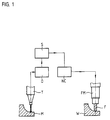
- FIG. 1 an arrangement for milling free-form surfaces is shown schematically.
- a button T scans a model M of a workpiece W in a known manner.
- Data is obtained from the surface of the scanned model M.
- the data obtained in this way are processed in a digitizing unit D and stored in a digital memory S.
- the digital memory S can be of any type, for the NC milling machine described here it is a floppy disk drive.
- the data are read out again from the diskette and fed to the NC control which controls the milling cutter F in the milling machine FM in accordance with the processed data. This creates - within the digitization accuracy - a workpiece W with the same geometry as the model M.
- the button T and the milling cutter F can be chosen identically in shape and diameter.
- the path of the tool center is directly available. Therefore, the database can be used directly for the production of the workpiece W without any further influence.
- FIG. 2 shows a spatial surface in a Cartesian coordinate system with the axes X, Y and Z.
- Profile lines L are created in the surface by laying flat cuts KE.
- An infinite number of plane cuts KE is necessary for a complete description of the area via such profile lines L.
- the technical generation of the spatial area is generally realized by recording the profile shape in a plane section KE parallel to an axis.
- the speed in the X axis remains zero.
- the surface is generated in layers over a finite number of cuts KE due to a real spatial expansion of the button T or tool F.
- the infeed movement between two planes only takes place as an actuating movement after the machining process has ended. In principle, this corresponds to 2 1/2 D path control.
- the plane spanned by the axes Y and Z within which the machining movement takes place is defined here as the copying plane KE.
- FIG. 3 shows how, for example, three copy planes KE1, KE2 and KE3 lie next to one another.
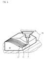
- the line-by-line machining can be seen from FIG. 4.
- both the scanning and the machining can be different, e.g. B. takes place on a circular or sawtooth-shaped path. Only a sufficient amount of data needs to be obtained.
- a spatial surface can also be described by an infinitely large number of points which are related to a reference plane which is defined by two coordinate axes of a three-dimensional coordinate system. Each of these points is then assigned a value in the third coordinate axis, which corresponds to the distance of the spatial surface from the reference plane at this point.
- a finite number of raster points is assumed in the plane spanned by the X and Y axes, and a height coordinate Z is assigned to each raster point. These values form the longitude, latitude and height data.
- the digitization can be used to store a coordinate value Z for the height of the model M at the scanning point in the form of height data at each memory location of the digital memory S. This value is then fed to the NC control, with the aid of which the workpiece W is manufactured.
- the machining process corresponds to the machining process, both of which are carried out row by row, which means that the matrix of the scanning points is formed from a number of rows and columns, the intersection points forming the grid of the contour elements Wi of the spatial matrix.
- the data of the workpiece W are compared with those of the tool F and the comparison result leads to relative movements between the workpiece W and the tool F.
- the tool F is guided over the workpiece W in accordance with its predetermined center path so that the contour is ultimately of the workpiece W forms, which is determined by the dimension data of the workpiece W and is derived from the model.
- the collision analysis is carried out in such a way that the data of the contour elements Wk of the matrix in the vicinity of the tool F are checked for overlap with the relative tool data, and the position of the tool F is controlled so that the contour element Fi of the tool F and the contour element
- the spatial matrix which determines the surface shape of the workpiece W and which is closest to the tool F just touch.
- the point closest to the cutter on the desired workpiece surface can be determined by directly comparing the dimensions of the workpiece W, which are present as digital data, with the digital dimension data of the tool F. In practice, this is done by forming a difference, as can be seen from FIG. 5.
- a further possibility of determining the relevant data consists in that only a "height comparison" takes place between the data of the spatial matrix of the workpiece W and that of the tool F in the projection onto the workpiece W, which also amounts to forming a difference.
- the position of the tool F thus depends not only on the desired surface of the workpiece W, but also on whether a contour elevation is present in the immediate vicinity of the tool F. This contour elevation is recognized and the positioning of the tool F is controlled so that the tool F just touches this contour elevation.
- the correction data for the cutter center path can be determined particularly advantageously if the aforementioned spatial matrix is made up of equally spaced rows and columns, so that each contour element Wk is assigned an X and a Y coordinate in a rigid grid, the surface contour of the workpiece W is represented by the set of height coordinates Z with certain numerical values at the respective address X / Y.
- the machining process can be controlled so that one line of the matrix corresponds to one feed line of line-by-line processing.
- the machining process can be controlled so that one line of the matrix corresponds to one feed line of line-by-line processing.
- not every contour element (Wk, Fk) within the tool projection has to be checked for the collision analysis, but it is sufficient to check the contour elements that are in the column of the matrix that is perpendicular to the tool axis. To do this, it is necessary to determine an equidistant for the profile line in advance in the line currently being edited. This measure considerably reduces the effort of data comparison.
Landscapes
- Physics & Mathematics (AREA)
- General Physics & Mathematics (AREA)
- Engineering & Computer Science (AREA)
- Automation & Control Theory (AREA)
- Numerical Control (AREA)
Applications Claiming Priority (2)
| Application Number | Priority Date | Filing Date | Title |
|---|---|---|---|
| DE3804743A DE3804743A1 (de) | 1988-02-16 | 1988-02-16 | Nachformanordnung |
| DE3804743 | 1988-02-16 |
Publications (3)
| Publication Number | Publication Date |
|---|---|
| EP0328750A2 EP0328750A2 (de) | 1989-08-23 |
| EP0328750A3 EP0328750A3 (en) | 1990-08-16 |
| EP0328750B1 true EP0328750B1 (de) | 1993-12-29 |
Family
ID=6347479
Family Applications (1)
| Application Number | Title | Priority Date | Filing Date |
|---|---|---|---|
| EP88119753A Expired - Lifetime EP0328750B1 (de) | 1988-02-16 | 1988-11-26 | Nachformanordnung |
Country Status (4)
| Country | Link |
|---|---|
| US (1) | US5003484A (enExample) |
| EP (1) | EP0328750B1 (enExample) |
| JP (1) | JP2588603B2 (enExample) |
| DE (3) | DE3804743A1 (enExample) |
Families Citing this family (33)
| Publication number | Priority date | Publication date | Assignee | Title |
|---|---|---|---|---|
| DE59009295D1 (de) * | 1990-04-02 | 1995-07-27 | Heidenhain Gmbh Dr Johannes | Digitalisier-Verfahren mit Kollisionsprüfung. |
| DE4028324A1 (de) * | 1990-09-06 | 1992-03-12 | Reichenbacher Gmbh | Bildhauerkopiermaschine |
| EP0482848B1 (en) * | 1990-10-22 | 1996-06-12 | Canon Kabushiki Kaisha | Image recording apparatus |
| US5291393A (en) * | 1990-10-22 | 1994-03-01 | Toshiba Kikai Kabushiki Kaisha | NC machine tool apparatus having means for producing NC work program and method thereof |
| SE468198B (sv) * | 1990-12-12 | 1992-11-23 | Nobelpharma Ab | Foerfarande och anordning foer framstaellning av individuellt utformade tredimensionella kroppar anvaendbara som tandersaettningar, proteser, etc |
| JP2757590B2 (ja) * | 1991-07-04 | 1998-05-25 | 三菱電機株式会社 | 数値制御装置 |
| SE469158B (sv) * | 1991-11-01 | 1993-05-24 | Nobelpharma Ab | Dental avkaenningsanordning avsedd att anvaendas i samband med styrning av en verkstadsutrustning |
| US5454422A (en) * | 1992-10-29 | 1995-10-03 | Kitagawa Kogyo Co., Ltd. | Woodworking machines |
| SE501411C2 (sv) * | 1993-07-12 | 1995-02-06 | Nobelpharma Ab | Förfarande och anordning vid tredimensionell kropp användbar i människokroppen |
| SE501410C2 (sv) * | 1993-07-12 | 1995-02-06 | Nobelpharma Ab | Förfarande och anordning i samband med framställning av tand, brygga, etc |
| DE4415659C1 (de) * | 1994-05-04 | 1995-11-30 | Reimond Bernstein | Vorrichtung und Verfahren zur Herstellung von Gegenständen auf der Grundlage von Daten, die aus einer optischen Erfassung eines Objektes ermittelt werden |
| DE19929557B4 (de) | 1999-06-18 | 2006-01-19 | Dr. Johannes Heidenhain Gmbh | Verfahren und Schaltkreis zur Einstellung einer Schaltschwelle eines Tastschalters |
| SE0001042D0 (sv) * | 2000-03-24 | 2000-03-24 | Bengt-Goeran Rosen | Förfarande för framställande av en textur på en yta |
| US7291364B2 (en) * | 2000-04-06 | 2007-11-06 | Solid Terrain Modeling | Hi-resolution three-dimensional imaging apparatus for topographic and 3d models |
| US7216003B2 (en) * | 2000-04-06 | 2007-05-08 | Solid Terrain Modeling | Hi-accuracy three-dimensional topographic modeling apparatus |
| US6447223B1 (en) * | 2000-06-07 | 2002-09-10 | Parametric Technology Corporation | Control for high speed cutting tool |
| DE10157174A1 (de) * | 2001-11-22 | 2003-06-05 | Wolfgang Madlener | Verfahren und Vorrichtung zum räumlichen Vermessen von Werkstücken an einer Werkzeugmaschine |
| DE10330831A1 (de) * | 2003-07-08 | 2005-02-10 | Mtu Aero Engines Gmbh | Fräsverfahren zur Fertigung von Bauteilen |
| DE102007059568A1 (de) * | 2007-12-11 | 2009-06-18 | Mtu Aero Engines Gmbh | Tauchfräsverfahren |
| US8986009B2 (en) * | 2008-05-08 | 2015-03-24 | Degudent Gmbh | Method for determining 3-D data from at least one prepared maxillary area |
| ES2390548B1 (es) * | 2010-09-07 | 2013-06-06 | Alejandro Altuna, S.A. | Dispositivo para maquinas reproductoras de llaves que tienen su clave talladas en las caras planas laterales del paleton |
| DE102011009983A1 (de) * | 2011-02-01 | 2013-01-31 | FM SYSTEME FÖRDER- UND MONTAGETECHNIK Schmalzhofer GmbH | Vorrichtung und Verfahren zum Erfassen der Umrisse von Gegenständen und Bauteilen |
| US8489224B2 (en) | 2011-02-28 | 2013-07-16 | Solidcam Ltd. | Computerized tool path generation |
| US9690282B2 (en) | 2011-02-28 | 2017-06-27 | Solidcam Ltd. | Computerized tool path generation |
| JP6333385B2 (ja) * | 2013-08-29 | 2018-05-30 | ソリッドカム リミテッド | コンピュータ化されたツールパス生成 |
| CN105571548B (zh) * | 2016-01-08 | 2017-12-15 | 北京理工大学 | 一种微细切削测量转换装置及其公差预测方法 |
| DE102016214437A1 (de) * | 2016-08-04 | 2018-02-08 | ModuleWorks GmbH | Verfahren zur Bestimmung von Bearbeitungsbereichsgrenzen für eine 3+2-Achsen-Bearbeitung |
| DE102017219512B4 (de) * | 2017-11-02 | 2019-12-24 | ModuleWorks GmbH | Verfahren zur Herstellung einer Bein- oder Fußprothese durch spanende Bearbeitung |
| CN108356294A (zh) * | 2018-02-14 | 2018-08-03 | 福州大学 | 一种特形面靠模加工装置 |
| US10857600B2 (en) * | 2018-09-28 | 2020-12-08 | The Boeing Company | Replicated hole pattern for remotely located structural components |
| JP6670961B1 (ja) * | 2019-02-27 | 2020-03-25 | 株式会社アマダホールディングス | 加工見積もり装置、加工見積もり方法、及び加工見積もりプログラム |
| CN110276095B (zh) * | 2019-05-05 | 2023-03-24 | 广东省汉兴科技有限公司 | 一种工件模型轮廓线形状自适应分解方法及装置 |
| CN114147242B (zh) * | 2021-12-08 | 2023-02-28 | 南阳勤大钢管科技有限公司 | 一种轧辊修形装置 |
Family Cites Families (11)
| Publication number | Priority date | Publication date | Assignee | Title |
|---|---|---|---|---|
| JPS5424156B1 (enExample) * | 1971-02-03 | 1979-08-18 | ||
| JPS55110307A (en) * | 1979-02-16 | 1980-08-25 | Oki Electric Ind Co Ltd | Correcting method for cutter diameter |
| WO1981001061A1 (fr) * | 1979-10-02 | 1981-04-16 | Daihatsu Motor Co Ltd | Procede de commande d'une machine outil a commande numerique |
| DE3213434C1 (de) * | 1982-04-10 | 1983-10-27 | Günther Dr.med. 7400 Tübingen Aldinger | Verfahren zur Herstellung individuell gestalteter Endoprothesen oder Implantate |
| JPS59107845A (ja) * | 1982-12-07 | 1984-06-22 | Fanuc Ltd | ならい制御方法 |
| JPS59224240A (ja) * | 1983-05-31 | 1984-12-17 | Fanuc Ltd | ならい制御装置 |
| DE3403677A1 (de) * | 1984-02-03 | 1985-08-08 | Dr. Johannes Heidenhain Gmbh, 8225 Traunreut | Verfahren zum erzeugen von werkstueckkonturen |
| JP2561908B2 (ja) * | 1985-03-29 | 1996-12-11 | 三菱電機株式会社 | 数値制御装置および数値制御方法 |
| JPH074739B2 (ja) * | 1985-07-01 | 1995-01-25 | フアナツク株式会社 | デジタイジング方法 |
| SE469321B (sv) * | 1986-04-14 | 1993-06-21 | Joenkoepings Laens Landsting | Saett och anordning foer att framstaella en modifierad tredimensionell avbildning av ett elastiskt deformerbart foeremaal |
| JPH0766290B2 (ja) * | 1986-06-26 | 1995-07-19 | 東芝機械株式会社 | 工具経路生成方法 |
-
1988
- 1988-02-16 DE DE3804743A patent/DE3804743A1/de active Granted
- 1988-02-16 DE DE8816754U patent/DE8816754U1/de not_active Expired - Lifetime
- 1988-11-26 EP EP88119753A patent/EP0328750B1/de not_active Expired - Lifetime
- 1988-11-26 DE DE88119753T patent/DE3886731D1/de not_active Expired - Fee Related
-
1989
- 1989-02-06 US US07/306,981 patent/US5003484A/en not_active Expired - Lifetime
- 1989-02-16 JP JP1035158A patent/JP2588603B2/ja not_active Expired - Lifetime
Non-Patent Citations (1)
| Title |
|---|
| WERKSTATTSTECHNIK, ZEITSCHRIFT FUR INDUSTRIELLE FERTIGUNG. vol. 62, no. 9, September 1972, BERLIN DE Seiten 544-548;STUTE G.& EISINGER J.: "DIE FRÄSERBAHNABWEICHUNG BEI EINER NUMERISCH GESTEUERTEN 5-ACHSEN-FRÄSMASCHINE" * |
Also Published As
| Publication number | Publication date |
|---|---|
| EP0328750A2 (de) | 1989-08-23 |
| JPH01246046A (ja) | 1989-10-02 |
| DE3804743A1 (de) | 1989-08-24 |
| JP2588603B2 (ja) | 1997-03-05 |
| EP0328750A3 (en) | 1990-08-16 |
| DE3804743C2 (enExample) | 1989-11-16 |
| DE3886731D1 (de) | 1994-02-10 |
| DE8816754U1 (de) | 1990-07-05 |
| US5003484A (en) | 1991-03-26 |
Similar Documents
| Publication | Publication Date | Title |
|---|---|---|
| EP0328750B1 (de) | Nachformanordnung | |
| DE3805500C2 (enExample) | ||
| DE69106222T2 (de) | Vorrichtung zur kontinuierlichen Fehlermessung von Werkstückformen und Messverfahren zur Anwendung der Vorrichtung. | |
| DE69119762T2 (de) | Mehrfunktionsmesssystem | |
| DE69108183T2 (de) | Verfahren zur Regelung der dimensionalen Messung von Gussstücken. | |
| EP0754992A1 (de) | Verfahren und Vorrichtung für die Herstellung von dreidimensionalen Bauteilen | |
| DE3134315A1 (de) | Verfahren zum modifizieren programmierter positionenunter verwendung eines programmgesteuerten oberflaechen-fuehlelements | |
| DE3833715A1 (de) | Interaktives system fuer die mathematische darstellung eines modells | |
| DE4105314A1 (de) | Dreidimensionaler plotter | |
| EP0769677A2 (de) | Verfahren zur Koordinatenmessung an Werkstücken | |
| DE60008512T2 (de) | System und verfahren zum nachprüfen der position eines werkzeuges einer werkzeugmaschine | |
| EP1078305B1 (de) | Koordinatenmessgerät und verfahren zur steuerung eines solchen | |
| DE3854229T2 (de) | Verfahren zum vorbereiten der numerischen steuerungsdaten für ein schneidverfahren. | |
| DE4223483C2 (de) | Verfahren zur Bestimmung der Form- und Lageabweichungen von Fertigungsteilen | |
| DE68906669T2 (de) | Messsystem fuer eine werkzeugeinstellung in einer werkzeugmaschine. | |
| DE3928548A1 (de) | Verfahren zum festlegen eines bearbeitungsprozesses bei der generierung von nc-information | |
| EP0477398A2 (de) | Verfahren für die Bearbeitung von Werkstücken mit numerisch gesteuerten Maschinen | |
| DE4006949C5 (de) | Verfahren zum punktweisen Abtasten der Oberfläche eines Werkstücks | |
| EP0613573B1 (de) | Verfahren zur überprüfung der arbeitsgenauigkeit einer nc-maschine | |
| EP1850089B1 (de) | Vorrichtung und Verfahren zum räumlichen Vermessen von Werkstücken an einer Werkzeugmaschine | |
| EP0450113B1 (de) | Digitalisier-Verfahren mit Kollisionsprüfung | |
| DE69323795T2 (de) | Numerische Steuerungsvorrichtung zur Werkzeugführung entlang nicht-orthogonaler mechanischer Achsen | |
| DE4323573C2 (de) | Verfahren zum Bestimmen einer Schnitttrajektorie in einem NC-Bearbeitungssystem | |
| DE4102688A1 (de) | Numerisch gesteuertes vorschubgeraet und verfahren zum ausfuehren einer vorschubtaetigkeit | |
| DE4326988A1 (de) | Verfahren zur Steuerung von Werkzeugmaschinen |
Legal Events
| Date | Code | Title | Description |
|---|---|---|---|
| PUAI | Public reference made under article 153(3) epc to a published international application that has entered the european phase |
Free format text: ORIGINAL CODE: 0009012 |
|
| 17P | Request for examination filed |
Effective date: 19881206 |
|
| AK | Designated contracting states |
Kind code of ref document: A2 Designated state(s): AT CH DE ES FR GB IT LI NL SE |
|
| PUAL | Search report despatched |
Free format text: ORIGINAL CODE: 0009013 |
|
| AK | Designated contracting states |
Kind code of ref document: A3 Designated state(s): AT CH DE ES FR GB IT LI NL SE |
|
| 17Q | First examination report despatched |
Effective date: 19921006 |
|
| RBV | Designated contracting states (corrected) |
Designated state(s): DE FR GB IT |
|
| ITF | It: translation for a ep patent filed | ||
| GRAA | (expected) grant |
Free format text: ORIGINAL CODE: 0009210 |
|
| AK | Designated contracting states |
Kind code of ref document: B1 Designated state(s): DE FR GB IT |
|
| REF | Corresponds to: |
Ref document number: 3886731 Country of ref document: DE Date of ref document: 19940210 |
|
| GBT | Gb: translation of ep patent filed (gb section 77(6)(a)/1977) |
Effective date: 19940114 |
|
| ET | Fr: translation filed | ||
| PLBE | No opposition filed within time limit |
Free format text: ORIGINAL CODE: 0009261 |
|
| STAA | Information on the status of an ep patent application or granted ep patent |
Free format text: STATUS: NO OPPOSITION FILED WITHIN TIME LIMIT |
|
| 26N | No opposition filed | ||
| REG | Reference to a national code |
Ref country code: GB Ref legal event code: IF02 |
|
| PGFP | Annual fee paid to national office [announced via postgrant information from national office to epo] |
Ref country code: GB Payment date: 20021030 Year of fee payment: 15 |
|
| PGFP | Annual fee paid to national office [announced via postgrant information from national office to epo] |
Ref country code: FR Payment date: 20021104 Year of fee payment: 15 |
|
| PG25 | Lapsed in a contracting state [announced via postgrant information from national office to epo] |
Ref country code: GB Free format text: LAPSE BECAUSE OF NON-PAYMENT OF DUE FEES Effective date: 20031126 |
|
| GBPC | Gb: european patent ceased through non-payment of renewal fee |
Effective date: 20031126 |
|
| PG25 | Lapsed in a contracting state [announced via postgrant information from national office to epo] |
Ref country code: FR Free format text: LAPSE BECAUSE OF NON-PAYMENT OF DUE FEES Effective date: 20040730 |
|
| REG | Reference to a national code |
Ref country code: FR Ref legal event code: ST |
|
| PGFP | Annual fee paid to national office [announced via postgrant information from national office to epo] |
Ref country code: DE Payment date: 20041105 Year of fee payment: 17 |
|
| PG25 | Lapsed in a contracting state [announced via postgrant information from national office to epo] |
Ref country code: IT Free format text: LAPSE BECAUSE OF NON-PAYMENT OF DUE FEES;WARNING: LAPSES OF ITALIAN PATENTS WITH EFFECTIVE DATE BEFORE 2007 MAY HAVE OCCURRED AT ANY TIME BEFORE 2007. THE CORRECT EFFECTIVE DATE MAY BE DIFFERENT FROM THE ONE RECORDED. Effective date: 20051126 |
|
| PG25 | Lapsed in a contracting state [announced via postgrant information from national office to epo] |
Ref country code: DE Free format text: LAPSE BECAUSE OF NON-PAYMENT OF DUE FEES Effective date: 20060601 |