EP0328076B1 - Gerät zur Bildung dünner Schichten und durch Mikrowellen-Zerstäubung arbeitende Ionenquelle - Google Patents
Gerät zur Bildung dünner Schichten und durch Mikrowellen-Zerstäubung arbeitende Ionenquelle Download PDFInfo
- Publication number
- EP0328076B1 EP0328076B1 EP89102164A EP89102164A EP0328076B1 EP 0328076 B1 EP0328076 B1 EP 0328076B1 EP 89102164 A EP89102164 A EP 89102164A EP 89102164 A EP89102164 A EP 89102164A EP 0328076 B1 EP0328076 B1 EP 0328076B1
- Authority
- EP
- European Patent Office
- Prior art keywords
- plasma
- plasma generating
- generating chamber
- target
- ion source
- Prior art date
- Legal status (The legal status is an assumption and is not a legal conclusion. Google has not performed a legal analysis and makes no representation as to the accuracy of the status listed.)
- Expired - Lifetime
Links
Images


Classifications
-
- C—CHEMISTRY; METALLURGY
- C23—COATING METALLIC MATERIAL; COATING MATERIAL WITH METALLIC MATERIAL; CHEMICAL SURFACE TREATMENT; DIFFUSION TREATMENT OF METALLIC MATERIAL; COATING BY VACUUM EVAPORATION, BY SPUTTERING, BY ION IMPLANTATION OR BY CHEMICAL VAPOUR DEPOSITION, IN GENERAL; INHIBITING CORROSION OF METALLIC MATERIAL OR INCRUSTATION IN GENERAL
- C23C—COATING METALLIC MATERIAL; COATING MATERIAL WITH METALLIC MATERIAL; SURFACE TREATMENT OF METALLIC MATERIAL BY DIFFUSION INTO THE SURFACE, BY CHEMICAL CONVERSION OR SUBSTITUTION; COATING BY VACUUM EVAPORATION, BY SPUTTERING, BY ION IMPLANTATION OR BY CHEMICAL VAPOUR DEPOSITION, IN GENERAL
- C23C14/00—Coating by vacuum evaporation, by sputtering or by ion implantation of the coating forming material
- C23C14/22—Coating by vacuum evaporation, by sputtering or by ion implantation of the coating forming material characterised by the process of coating
- C23C14/34—Sputtering
- C23C14/35—Sputtering by application of a magnetic field, e.g. magnetron sputtering
- C23C14/354—Introduction of auxiliary energy into the plasma
-
- H—ELECTRICITY
- H01—ELECTRIC ELEMENTS
- H01J—ELECTRIC DISCHARGE TUBES OR DISCHARGE LAMPS
- H01J37/00—Discharge tubes with provision for introducing objects or material to be exposed to the discharge, e.g. for the purpose of examination or processing thereof
- H01J37/32—Gas-filled discharge tubes
- H01J37/34—Gas-filled discharge tubes operating with cathodic sputtering
- H01J37/3402—Gas-filled discharge tubes operating with cathodic sputtering using supplementary magnetic fields
-
- C—CHEMISTRY; METALLURGY
- C23—COATING METALLIC MATERIAL; COATING MATERIAL WITH METALLIC MATERIAL; CHEMICAL SURFACE TREATMENT; DIFFUSION TREATMENT OF METALLIC MATERIAL; COATING BY VACUUM EVAPORATION, BY SPUTTERING, BY ION IMPLANTATION OR BY CHEMICAL VAPOUR DEPOSITION, IN GENERAL; INHIBITING CORROSION OF METALLIC MATERIAL OR INCRUSTATION IN GENERAL
- C23C—COATING METALLIC MATERIAL; COATING MATERIAL WITH METALLIC MATERIAL; SURFACE TREATMENT OF METALLIC MATERIAL BY DIFFUSION INTO THE SURFACE, BY CHEMICAL CONVERSION OR SUBSTITUTION; COATING BY VACUUM EVAPORATION, BY SPUTTERING, BY ION IMPLANTATION OR BY CHEMICAL VAPOUR DEPOSITION, IN GENERAL
- C23C14/00—Coating by vacuum evaporation, by sputtering or by ion implantation of the coating forming material
- C23C14/22—Coating by vacuum evaporation, by sputtering or by ion implantation of the coating forming material characterised by the process of coating
- C23C14/34—Sputtering
- C23C14/35—Sputtering by application of a magnetic field, e.g. magnetron sputtering
- C23C14/354—Introduction of auxiliary energy into the plasma
- C23C14/357—Microwaves, e.g. electron cyclotron resonance enhanced sputtering
-
- H—ELECTRICITY
- H01—ELECTRIC ELEMENTS
- H01J—ELECTRIC DISCHARGE TUBES OR DISCHARGE LAMPS
- H01J27/00—Ion beam tubes
- H01J27/02—Ion sources; Ion guns
- H01J27/16—Ion sources; Ion guns using high-frequency excitation, e.g. microwave excitation
- H01J27/18—Ion sources; Ion guns using high-frequency excitation, e.g. microwave excitation with an applied axial magnetic field
-
- H—ELECTRICITY
- H01—ELECTRIC ELEMENTS
- H01J—ELECTRIC DISCHARGE TUBES OR DISCHARGE LAMPS
- H01J37/00—Discharge tubes with provision for introducing objects or material to be exposed to the discharge, e.g. for the purpose of examination or processing thereof
Definitions
- the present invention relates to apparatuses for forming thin films on specimen substrates and apparatuses for extracting ions for forming thin films on specimen substrates, etching the surface of a thin film or improving the quality of the surface of a thin film, and more particularly a novel film forming apparatus capable of forming thin films of various materials at a high film growing rate with a high efficiency and stability for a long period of time by utilizing high-density plasma generated by electron cyclotron resonance and a novel sputtering type ion source cable of extracting various ions of high current density with a high efficiency and stability for a long period of time. Furthermore, the present invention relates to a plasma generating apparatus which is capable of generating high-density plasma in a gas under a low pressure and which can be utilized with the film forming apparatus and the ion source.
- the discharge cannot be maintained in a stable manner in a low gas pressure range less than 0.133 Pa (10 ⁇ 3 Torr) and plasma is generated only at a gas pressure of the order of or higher than 1.33 Pa (10 ⁇ 2 Torr), so that there arises the problem that a large amount of impurities are penetrated into the thin film.
- the particles which contribute to the growth of a thin film are almost neutral and it has been difficult to control the energy of such neutral particles.
- the magnetron sputtering apparatuses for instance, as disclosed by R. K. Waits, J. Vac. Sci. Technol., Vol. 15 (1978), pp.179-187) and the facing targets sputtering apparatuses (for instance, as disclosed by M. Matsuoka et al., J. Apply. Phys., Vol. 60 (1986), pp.2096-2102) which permit a high-rate sputtering in a gas under a low pressure have been devised and demonstrated.
- the high-energy secondary electrons are trapped over the surface of the target by the effects of the magnetic field closed over the surface of the target and the electric field over the surface of the target so that high-density plasma can be generated in a gas at a low pressure.
- they have the problem that the qualities of the portions of a grown film corresponding to the eroded portions of the target and to the not eroded portions, respectively, are widely different from each other.
- the target is made of a magnetic material such as Fe, the magnetic flux does not leak to the surface of the target so that high-density plasma cannot be generated and kinds of thin films to be formed are limited.
- Fig. 1 shows a conventional facing targets sputtering apparatus.
- a sputtering chamber 1 can be evacuated by a vacuum pump and gases for generating plasma are introduced from gas inlet 2.
- substrate holder 3 for supporting a substrate 4 is disposed.
- a heater 5 is incorporated in the holder 3.
- Two targets 6 and 7 are arranged in opposing relationship with each other.
- Magnets 8 and 9 for applying magnetic field on the targets 6 and 7 are incorporated in target holders 10 and 11, respectively.
- Target holders are electrically insulated from the chamber 1 by insulators 12 and 13. When discharge is effected in the chamber 1, the high-energy secondary electrons are confined between the targets to generate high-density plasma between targets.
- the targets 6 and 7 are disposed in opposing relationship and are spaced apart from each other by a suitable distance, so that the substrate 4 must be located at a horizontal position and the deposition rate of the sputtered particles deposited over the surface of the substrate 4 is low. Furthermore, in the case of coating a large surface ot a large-sized disc or the like, there arises the problem that the deposition rate or efficiency is essentially low when the targets are disposed in the manner described above.
- ECR microwave plasma deposition apparatus which utilizes electron cyclotron resonance (ECR) plasma and sputtering (for instance, as disclosed S. Matsuo et al. U.S. Patent No. 4,492,620).
- ECR electron cyclotron resonance
- This apparatus offers an excellent method for forming thin films at low temperatures by combining the supply of a metal by sputtering with the irradiation of a substrate with microwave plasma.
- the density of the microwave plasma must be increased so that there arises a defect that damages to a thin film being grown and to a substrate are increased.
- the ion sources which utilize an ion extracting mechanism such as a grid to extract the ions produced in plasma have been widely used for forming thin films of various materials, etching the surface of a formed thin film, processing the formed thin films and so on.
- the evaporation type ion sources and the sputtering type ion sources are well known to those skilled in the art.
- the evaporation type ion sources must maintain the temperature within its furnace at high temperatures, so that the vaporized particles are ionized and consequently impurities most frequently tend to be contained in a thin film being grown.
- the extraction of ions of a material having a high melting point is difficult (for instance, as disclosed by M. A. Hasan et al., J. Vac Sci. Technol., Vol. B5 (1987), pp.1332-1339).
- the plasma density In order to realize a high-current ion source by utilizing sputtering, the plasma density must be maintained at a high level with a high efficiency. To this end, the secondary electrons emitted from the target must be efficiently confined, but the conventional ion sources cannot satisfactorily confine the secondary electrons.
- the ions of metals or materials having a high melting point can not be extracted and ion extraction can be continued for a long period of time in a stable manner.
- one of the objects of the present invention is to provide a thin film forming apparatus which can substantially solve the above and other problems encountered in the conventional thin film forming apparatuses, can carry out the sputtering process by utilizing high-density ECR plasma generated at a low gas pressure and can continuously form a high quality thin film on a substrate maintained at a low temperature, at a high deposition rate and at a high efficiency without causing any damage to the thin film being grown and the substrate by sputtered particles with a high ionization rate and a low level of energy.
- Another object of the present invention is to provide a sputtering type ion source utilizing ECR plasma which can extract high purity ions of almost all materials such as metals, inert gases, reactive gases and the like at a low gas pressure over a wide energy range at a high yield in a stable manner for a long period of time.
- a further object of the present invention is to provide an apparatus capable of generating high-density ECR plasma at a low gas pressure which can be utilized in the thin film forming apparatus and the ion source as well.
- a plasma generating apparatus comprises the features mentioned in claim 1.
- This apparatus can be used in an ion source (claim 2) also without extraction mechanism (claim 15).
- claim 2 also without extraction mechanism
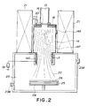
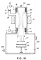
- FIG. 2 is a sectional view illustrating a first embodiment of a thin film forming apparatus in accordance with the present invention in which a plasma generating apparatus is combined with a specimen chamber.
- a plasma generating chamber 14 comprises a plasma generating section 14P and a target mounting section 14S.
- a gas for generating plasma is introduced through a gas inlet 14A into the plasma generating chamber 14 which is also communicated with a microwave waveguide 15.
- the microwave is introduced from a microwave source connected to a microwave introduction mechanism composed of an oscillator, a matching device, a microwave watmater, an isolator and so on through a microwave introduction window 16 into the plasma generation chamber 14 in the axial direction of plasma to be generated.
- the microwave introduction window 16 is made of a quartz glass sheet.
- the microwave source for instance, a magnetron with a frequency of 2.45 GHZ.
- a tube-like target 17 is mounted on the inner surface of the target mounting section 14S.
- a ring-shaped target 18 is mounted within the plasma generating chamber 14 at the top portion thereof.
- a cylindrical target 17 is used as a tube-like target, but it is to be understood that a polygonal target may be used and that the cross section of the target 17 may be in the form of a circular or polygonal ring continuously or discontinuously extended in the circumferential direction.
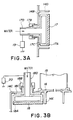
- Figs. 3A and 3B illustrate the method for mounting the targets 17 and 18 in the plasma generating chamber.
- the target 17 is removably mounted on a target mount 17A made of a metal.
- Target mount 17A may be water cooled and is securely attached with an internally threaded cap 17B to a side wall 14B of the plasma generating chamber 14.
- An insulator 17C is interposed between the target mount 17A and the side wall 14B.
- the target 18 is removably mounted on a target mount 18A made of a metal.
- Target mount 18A may be water cooled, and is securely attached through an insulator 18C to the wall 14C with an internally threaded cap 18B.
- the horizontally and vertically extended portions 17D and 18D of the target mounts 17A and 18A also serve as electrodes which are electrically connected to DC power supplies 19 and 20, respectively, so that the negative voltages can be applied to the targets 17 and 18, respectively.
- the plasma generating section 17P uses, for instance, a circular cavity resonance mode TE113 which is one of the conditions of the microwave cavity resonator. That is, it is in the form of a cylinder 20 cm in inner diameter and 20 cm in height in order to increase not only the electric field strength of the microwave but also the efficiency of the microwave discharge.
- the bottom of the plasma generating section 14P; that is, the interface between the section 14P and the target mounting section 14S has an opening 10 cm in diameter. The interface acts as a reflecting surface for the microwave.
- the plasma generating section 14P functions as a cavity resonator.
- the plasma generating chamber 14 is surrounded with at least one electromagnet 21 which produces a magnetic field in the chamber 14.
- various construction conditions are so determined that the conditions for producing the electron cyclotron resonance by the microwave may be satisfied within the plasma generating section 14P.
- the ECR condition for the microwave at the frequency of 2.45 GHz is the magnetic flux density of 8.75 ⁇ 10 ⁇ 2 T (875 G) so that the electromagnet 21 is so designed and constructed as to attain, for instance, the maximum density of 0.2 T (2000 G) and the magnetic flux density 875 G is obtainable anywhere within the plasma generating section 14P.
- the energy is imparted to the electrons at a high efficiency and the magnetic field established within the section 14P prevents the produced ions and electrons from scattering in the direction perpendicular to the magnetic field so that high-density plasma is generated at a low gas pressure.
- the cylindrical target 17 and the ring-shaped target 18 are so disposed that the magnetic flux 22 from the electromagnet 21 enters the surfaces of the targets 17 and 18 and furthermore the magnetic flux leaves one target and enters the other target.
- the plasma generating chamber is so designed and constructed that it may be cooled with water and that in order to protect the side surfaces of the targets 17 and 18 from plasma, they are surrounded by shields 14D and 14E, respectively, which are extended horizontally and vertically, respectively, from the inner wall surfaces of the plasma generating chamber 14.
- a gas is introduced through the gas inlet 14A into the plasma generating chamber 14 while the microwave is introduced therein and the discharge is effected under the ECR condition to generate high-density plasma.
- the magnetic flux extended between two targets serves to prevent the secondary electrons ( ⁇ electrons) emitted from the surfaces of the targets from scattering in the direction perpendicular to the magnetic field and furthermore to confine plasma.
- high-density plasma is generated at a low gas pressure.
- Plasma thus generated sputters the targets so as to knock-on ions and neutral particles.
- the knocked-on ions and neutral particles are extracted as sputtered particles.
- the bottom of the plasma generating chamber 14 is communicated with the specimen chamber 23 into which can be introduced a gas through a gas inlet 23A and which can be evacuated to a high vacuum by an exhaust system via gas outlet 23B.
- a substrate holder 24 which supports a substrate 25, and a shutter 26 which can be opened or closed is disposed above the substrate holder 24. In the other embodiments to be described hereinafter, sometimes the shutter 26 is not shown.
- a heating element is embedded into the substrate holder 24 for heating the same and that a DC or AC voltage is applied to the substrate 25 so that the bias voltages can be applied to the substrate 25 upon which a thin film is being grown and the substrate can be cleaned by sputtering.
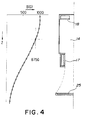
- Fig. 4 illustrates a distribution of the magnetic field strength in the direction of the magnetic flux in the first embodiment shown in Fig. 2.
- the magnetic field is a diverging magnetic field.
- a gas is introduced into the plasma generating chamber and is generated the plasma under ECR condition.
- the ring-shaped target 18 which is water cooled is mounted in the vicinity of the top of the plasma generating chamber within the latter and the cylindrical target 17 which is also water cooled is mounted at the outlet of the plasma generating chamber communicated with the specimen chamber so as to surround generated plasma.
- the microwave introduction window 16 is disposed at the center of the ring-shaped target 18 so that the microwave is introduced through the center of the ring-shaped target 18 into the plasma generating chamber 14.
- the first embodiment is so designed and constructed that the magnetic flux 22 produced by the electromagnet 21 extends between the surfaces of the cylindrical target 17 and the ring-shaped target 18. In other words the magnetic flux leaves the surface of one target and enter the surface of the other target.
- the electrons in generated high-density plasma have the mobility which is extremely higher than that of ions. Electrons are confined by the magnetic flux 22 and while making spiral motion around the magnetic flux 22 and while maintaining their angular momentum, they are accelerated toward in the direction of the target depending upon the gradient of the magnetic field.
- the negative voltage Va c and Va p are applied to the cylindrical target 17 and the ring-shaped target 18, respectively, which are now exposed to high-density plasma generated in the manner described above, the ions in high-density plasma are efficiently attracted to the cylindrical target 17 and the ring-shaped target 18 to sputter targets.
- the secondary electrons ( ⁇ electrons) 27 are emitted from the surfaces thereof.
- the secondary electrons 27 are accelerated by the electric fields produced by the targets, are confined by the magnetic flux and move with high-energy toward the opposite target while making spiral motion.
- the secondary electrons which have reached the opposite target are reflected by the electric field produced thereby.
- the secondary electrons 27 are confined between the targets while making spiral motion.
- reciprocally moving secondary electrons are confined until their energy becomes lower than the constraining force of the magnetic flux, and while they are confined, the ionization is accelerated by the collisions with the neutral particles and by the interaction with plasma.
- plasma is active, not only the stable discharge can be maintained at a low gass pressure of the order of 1.33 ⁇ 10 ⁇ 3 Pa (10 ⁇ 5 Torr), but also even at a relatively high gas pressure in which an active species plays an important roll, a thin film having a better crystal structures can be grown by the active plasma action on the substrate at a low temperature.
- the present invention since the ionization rate of plasma is high as described above, the ratio of the ionization of the sputtered particles in plasma is high. Hence, the so-called self-sputtering, that is, the repetitive sputtering of the target with the ionized particles which are sputtered and are accelerated again by the potential applied to the target becomes extremely high. That is, the present invention has a feature that even when a gas for generating plasma (for instance, Ar) is very thin or even when no gas is used, the above-mentioned self-sputtering is continued so that a highly pure thin film can be formed.
- a gas for generating plasma for instance, Ar
- the results of the formation of an AlN film by the thin film forming apparatus in accordance with the present invention will be described.
- the nitrogen (N2) was introduced at a rate of 2 cc/min and the gas pressure in the plasma generating chamber 14 was maintained at 3.99 ⁇ 10 ⁇ 2 Pa (3 x 10 ⁇ 4 Torr).
- a thin film was grown under the condition that the power of the introduced microwave was 100 - 500 W, the power applied to the Al target 17 was 100 - 800 W and the substrate holder was heated at 300 °C. The result was that AlN films were deposited at a deposition rate of 3 - 40 nm/min in a stable and efficient manner for a long period of time.
- Fig. 6 illustrates a discharge characteristic of the first embodiment when the voltage applied to the ring-shaped target was maintained at -500 V; the pressure of nitrogen gas was maintained at 0.399 Pa (3x10 ⁇ 3 Torr); and the microwave power was maintained at 300 W and 80 W.
- the first embodiment even when the voltages applied to the cylindrical target 17 and the ring-shaped target 18, respectively, are different from each other, sufficiently high-density plasma was generated. Furthermore even when the same voltage is applied to both the targets; that is, even when the targets are electrically connected to each other, high-density plasma could be generated at a considerably high degree of efficiency.
- the deposition rate increased linealy with the applied power.
- the mean energy of ions was varied from 5 eV to 30 eV.
- the thin film forming apparatus in accordance with the present invention is not limited to the formation of the AlN films and can be utilized to form the thin films of almost all materials.
- the gas to be introduced into the plasma generating chamber is not limited to the nitrogen gas and almost all the reactive gases may be used so that repetitive sputtering can be accomplished.
- various compounds may be used as targets so that thin films of almost all the materials can be formed.
- a second embodiment of a thin film forming apparatus in accordance with the present invention will be described.
- the gradient of the magnetic field established by the electromagnet 21 greatly influences the energy of each ion accelerated in the direction of the substrate, the distribution of errosion of the target or the shape of plasma.
- an auxiliary electromagnet 28 is additionally provided around the substrate in order to control the gradient of the magnetic field, thereby controlling the above-mentioned factors influenced by the gradient of the magnetic field of the electromagnet 21.
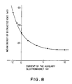
- Fig. 8 illustrates the variation in mean ion energy when the magnitude of current flowing through the auxiliary electromagnet 28 is varied.
- the positive current corresponds the case in which the direction of the magnetic field produced by the auxiliary electromagnet is the same with the direction of the magnetic field produced by the electromagnet 21, but the negative current corresponds to the case in which the direction of the magnetic field produced by the auxiliary electromagnet is opposite to the direction of the magnetic field produced by the magnet 21.
- the microwave introduction window 16 is connected through a vacuum waveguide 29 to the plasma generating chamber 14.
- the vacuum waveguide 29 interconnecting between the center portion of the ringshaped target 18 and the plasma generating chamber 14 is surrounded by a yoke 30 so that the magnetic flux in the vacuum waveguide 29 can be absorbed and the magnetic field strength can be sharply varied at the portion connecting the vacuum waveguide 29 with the plasma generating chamber 14.
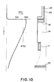
- Fig. 10 illustrates a distribution of the magnet field strength in the direction of the magnetic flux in the third embodiment.
- the plasma breeding mechanism in the third embodiment is substantially similar to that described above with reference to Fig. 5.
- the functions of the vacuum waveguide and the yoke are as follows. That is, in the case of the formation of an electrically conductive thin film, when the microwave introduction window 16 becomes dim or is contaminated, it becomes impossible to generate plasma for a long period of time. When only the microwave introduction window 16 is spaced apart from the plasma generating chamber and is connected thereto through the vacuum waveguide 29, the resonance condition is satisfied even in the vacuum waveguide so that plasma is generated in the vacuum waveguide 29. Furthermore it becomes also impossible to supply the microwave power effectively because the plasma is accelerated in the direction in which the microwave is introduced.
- the magnetic flux in the vacuum waveguide 29 is reduced and the magnetic field strength sharply changes at the boundary between the plasma generating chamber 14 and the vacuum waveguide 29 so that no plasma is generated in the vacuum waveguide and is accelerated in the direction thereof. In other words, plasma is not accelerated in the direction of the microwave introduction.
- the neutral particles which are not ionized are not influenced by the magnetic field and the electrical field so that they fly substantially straightly from the targets.
- the microwave window 16 when the microwave window 16 is located at a position at which the window 16 is not directly viewed from the targets, the contamination of the microwave introduction window 16 with the sputtered particles can be prevented.
- the contamination of the microwave introduction window 16 is prevented. Therefore it becomes possible to form a thin film of almost any material can be formed continuously in a stable manner for a long period of time.
- the specimen chamber 23 is evacuated to a vacuum of 6.65 ⁇ 10 ⁇ 5 Pa (5 x 10 ⁇ 7 Torr) and then Ar gas was introduced at a rate of 2 cc/min.
- the gas pressure in the plasma generating chamber 14 was maintained at 3.99 ⁇ 10 ⁇ 2 Pa (3 x 10 ⁇ 4 Torr) and a thin film was formed under the condition that the microwave power was maintained at 100 - 500 W; the power supplied to the Al target 17 was 100 - 800 W; and the substrate holder 24 was not heated and was maintained at room temperature.
- the Al films were formed at a deposition rate of 10 - 150 nm/min continuously in a stable and efficient manner for a long period of time.
- Fig. 11 illustrates a discharge characteristic of the third embodiment.
- the voltage applied to the ring-shaped target 18 was maintained at -500 V; the Ar gas pressure was maintained at 3.99 ⁇ 10 ⁇ 2 Pa (3x10 ⁇ 4 Torr); and the microwave power was maintained at 300 W and at 80 W.
- the microwave power was maintained at 300 W and at 80 W.
- the third embodiment even when the voltages applied to the cylindrical target 17 and the ring-shaped target 18 are different, sufficiently high density plasma can be generated. Furthermore when the same voltage is applied to both targets; that is even when the targets are electrically connected to each other, sufficiently high density plasma can be generate. In both cases, the mean energy of ions varies from 5 eV to 30 eV.
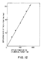
- Fig. 12 illustrates the dependence of the deposition rate or the film growth rate on the power supplied to the target. The deposition rate increased with the supplying power.
- the auxiliary electromagnet 28 for controlling the gradient of the magnetic field can be provided to surround the sides of the substrate so that the energy of each ion accelerated in the direction of the substrate, an erosion distribution of the target or the shape of plasma, all of which are influenced by the gradient of the magnetic field, can be controlled.
- the fourth embodiment is substantially similar in construction to the first embodiment described above with reference to Fig. 2 except that the electromagnet 21 is replaced by two ring-shaped permanent magnets 31 and 32. It is to be understood that instead of the ring-shaped permanent magnets 31 and 32, a plurality of bar magnets which are arranged radially may be used. In the third embodiment shown in Fig. 9, it may be also possible to replace the electromagnet 21 by one or more permanent magnets.
- the mode of operation of the fourth embodiment is substantially similar to those of the above-described embodiments.
- one or more permanent magnets can be used in combination with the yoke 30 described above.
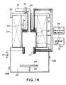
- Fig. 14 illustrates a fifth embodiment of the present invention which is substantially similar in construction to the third embodiment described above with reference to Fig. 9 except that the voltages are applied to the targets in addition to high frequency power. That is, when rf power from a rf generator 33 is applied through a matching network 34 to the targets 17 and 18, the effects substantially similar to those attained by the above-described embodiments can be attained. Furthermore, the fifth embodiment has a feature that even when the targets are not electrically conductive, the sputtering can be carried out effectively. It is of course apparent that the high frequency power may be supplied to the targets in the first embodiment described above with reference to Fig. 2.
- Fig. 15 schematically illustrates the construction of and the potential distribution in the direction of the magnetic flux in a sixth embodiment of the present invention.
- the essential difference from the first embodiment described above with reference to Fig. 2 is that the microwave is introduced into the plasma generating chamber 14 in the direction perpendicular to the axis of plasma to be generated or the magnetic flux at the center axis of the plasma generating chamber. That is, one end of the vacuum waveguide 29 is connected to the plasma generating chamber 14 perpendicular to the wall thereof and the other end of the vacuum waveguide 29 is connected through the microwave introduction window 16 to a microwave waveguide which in turn is connected to a microwave source (not shown).
- the microwave introduction window 16 is disposed at a position which cannot be viewed directly from the targets.
- the electromagnet 21 of the first embodiment (Fig. 2) is replaced by two electromagnets 21A and 21B.
- the magnetic fields produced by the electromagnets 21A and 21B, respectively, may be symmetrical or may be asymmetrical with each other.
- the center hole, through which microwave is introduced, of the ring-shaped target is not needed, thus a planar target 35 may be used instead of the ring-shaped target 18.
- the electromagnets 21A and 21B are so arranged that the magnetic field sufficient to cause ECR is produced and the magnetic flux leaves from one of the targets 17 and 35 and enters the other target within the plasma generating chamber 14.
- the sputtered particles are deposited on the substrate 25.
- Curve A is the distribution when the currents flowing through electromagnets 21A and 21B are 20A and 20A respectively, while curve B is that when the currents are 10A and 20A respectively.
- the magnetic field is a diverging magnetic field.
- a gas is introduced into the plasma generating chamber 14 and plasma is generated under the ECR condition.
- High-density plasma can be generated according to the plasma breeding mechanism described above with reference to Fig. 5.
- the negative voltages Va c and Va p are applied to the cylindrical target 17 and the planar target 35, respectively, exposed to high-density plasma thus generated, the ions in high-density plasma can be efficiently attracted to sputter the cylindrical target 17 and the planar target 35.
- the vacuum waveguide 29 is connected to the plasma generating chamber 14 in the direction perpendicular to the magnetic flux so that plasma is not accelerated in the direction of the introduction of the microwave.
- the neutral particles fly substantially straightly from the targets.
- the microwave introduction window 16 is located at a position which cannot be directly viewed from the targets, the contamination of the microwave introduction window 16 with the sputtered particles can be prevented.
- the microwave introduction window 16 is prevented from becoming dim so that a thin film of almost any material can be formed continuously in a stable manner for a long period of time.
- the magnetic field strength at the portion of the plasma generating chamber 14 where the microwave is introduced is made stronger than the magnetic field strength for inducing ECR, 8.75 ⁇ 10 ⁇ 2 T (875 G), in this case.
- the results of the formation of the Al films by utilizing the sixth embodiment will be described.
- Ar gas is introduced at a rate of 2 cc/min and the gas pressure in the plasma generating chamber 14 was maintained at 3.99 ⁇ 10 ⁇ 2 Pa (3 x 10 ⁇ 4 Torr).
- the formation of the Al films was carried out under the conditions that the microwave power was between 100 and 500 W and the power supplied to the cylindrical Al target 17 was between 100 and 800 W and the substrate holder temperature was maintained at room temperature.
- the results showed that the Al thin films can be continuously formed at a deposition rate of 10 - 150 nm/min in a stable and efficient manner for a long period of time.
- the mean energy of each ion was varied between 5 and 30 eV.
- Fig. 17 illustrates the discharge characteristic of the sixth embodiment under the conditions that the voltage applied to the planar target was - 500 V; Ar gas pressure was maintained at 3.99 ⁇ 10 ⁇ 2 and 0.399 Pa (0.3 and 3 m Torr); and the microwave power was maintained at 300 and 80 W.
- Curves C and E are discharge currents of the cylindrical target 17 and curves D and F are that of the planar target 35.
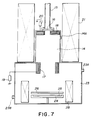
- the apparatuses shown in Figs. 2, 7, 9, 13, 14 and 15 can be modified in such a manner that the plasma generating chamber 14 does not comprise the target mounting section 14S and the cylindrical target 17 is mounted in the plasma generating section 14P.
- Fig. 18 illustrates a seventh embodiment of the present invention.
- the combination of the planar target and the cylindrical target is not used and instead the combination of two cylindrical targets 17 and 36 is utilized.
- the magnetic flux produced by the electromagnet 21 for producing the magnetic field leaves one target and enters the other target.
- the target 36 is detachably mounted on a mount 36A which is made of a metal and may be water cooled and is applied with the negative voltage from a power supply 20.
- An insulator 36C is interposed between the target mount 36A and the inner wall surface of the plasma generating chamber 14.
- the seventh embodiment when the high-energy ions impinge on the surfaces of the targets to which are applied the negative voltages, the high-energy secondary electrons ( ⁇ electrons) are emitted from the surfaces of the targets 17 and 36.
- the ⁇ electrons emitted from the targets are reflected by the electric fields produced by the targets 17 and 36 and are caused to make the reciprocal motion between the targets 17 and 36 while making the cyclotron motion around the magnetic flux extended between the targets 17 and 36.
- the seventh embodiment can generate high-density plasma even at a low gas pressure and sputtering of targets are carried out.
- the sputtered particles 37 are deposited on the substrate 25.
- the seventh embodiment can form a thin film at a high disposition rate as in the case of the sixth embodiment described above with reference to Fig. 15.
- the plasma generating chamber 14 may comprise the plasma generating section and the target mounting section in which the target 17 is mounted.
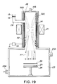
- Fig. 19 illustrates an eighth embodiment of the present invention in which is mounted only one cylindrical target 38 unlike the above-described embodiments.
- the target 38 is mounted on a mount 38A which is made of a metal and may be cooled and is applied with a negative voltage supplied from a power supply 19.
- An insulator 38C is interspaced between the cylindrical target 38 and the inner surface of the plasma generating chamber 14.
- the magnetic flux of the electromagnet 21 leaves one end portion of the target 38 and enters the other end portion thereof.
- the eighth embodiment can generate high-density plasma and extract sputtered particles 37 so that thin films can be formed at a high deposition rate.
- Fig. 20 illustrates in section a ninth embodiment of the present invention in which specimen chambers 23 and 23C are connected to both ends, respectively, of the plasma generating chamber 14 of the type described above with reference to Fig. 18. That is, the speciment chambers 23 and 23C are connected to the plasma generating chamber 14 in opposing relationship with each other.
- the specimen chamber 23C is provided with a gas inlet 23D, an exhaust system (not shown), a substrate holder 24A for supporting the substrate 25A and a shutter 26A.
- the ninth embodiment therefore, sputtered particles are extracted from both ends of the plasma generating chamber 14, whereby thin films are formed.
- one or more permanent magnets may be utilized.
- Fig. 21 illustrates a tenth embodiment of a thin film forming apparatus in accordance with the present invention which is substantially similar in construction to the sixth embodiment described above with reference to Fig. 15 except that an auxiliary electromagnet 28 is provided.
- the auxiliary electromagnet 28 may be disposed outside of the specimen chamber 23.
- the auxiliary electromagnet 28 is utilized to apply the magnetic field to the substrate 25 and the direction of this magnetic field is same as or opposite to the direction of the magnetic fields produced by the electromagnets 21A and 21B.
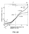
- Fig. 22 illustrates the distribution of the magnetic field strength in the direction of the magnetic flux.
- the curve G indicates the distribution of the magnetic field obtained when the current of 20A was made to flow through the electromagnets 21A and 21B and the direction of the magnetic flux induced by the auxiliary electromagnet 28 was same as the direction of the magnetic fluxes produced by the electromagnets 21A and 21B.
- the curve H illustrates the distribution obtained when the current of 20A was made to flow through the electromagnets 21A and 21B while no current was applied to the auxiliary electromagnet 28.
- the curve I illustrates the distribution obtained when the current of 10A was made to flow through the electromagnet 21A while the current of 20A was made to flow through the electromagnet 21B and the direction of the magnetic flux produced by the auxiliary electromagnet 28 was opposite to the direction of the magnetic fluxes produced by the electromagnets 21A and 21B.
- the curve J illustrates the distribution when the current of 10A was made to flow through the electromagnet 21A while the current of 20A was made to flow through the electromagnet 21B and no current was applied to the auxiliary electromagnet 28.
- the auxiliary electromagnet 28 is utilized to apply the magnetic field to the substrate 25 and the acceleration of the electrons in the direction of the substrate 25 is controlled by varying the gradient of the magnetic field produced by the auxiliary electromagnet 28 so that the energy of ions can be varied.
- Fig. 23 illustrates a variation in energy of incident ions on the substrate 25 when the magnitude of the current applied to the auxiliary electric magnet was varied.
- the magnetic flux entering cylindrical target 17 can be controlled, so that the fine control of the erosion distributions over the surfaces of the targets, the discharge condition and so on can be accomplished.
- the discharge characteristic as well as the dependence of the deposition rate on the power supplied to the target are substantially similar to those shown in Figs. 17 and 12, respectively.
- Fig. 24 illustrates a dependence of the reflection ratio of the microwave on the magnetic flux density at the connecting portion of the vaccum waveguide with the plasma generating chamber when the vacuum waveguide is connected in the direction perpendicular to the magnetic flux.
- the magnetic flux density at the connecting portion is made higher than that of the ECR condition, 8.75 ⁇ 10 ⁇ 2 T (875 gauss) for effectively introducing microwave.
- Fig. 25 illustrates dependence of the efficiency of the supplied microwave power on the angle ⁇ between the directions of the microwave introduction and of the magnetic flux.
- the efficiency of the microwave power means the ratio (Pf - Pr)/Pr, wherein Pf is a power of the incident microwave into the plasma and Pr is the power of microwave reflected from the plasma. Both of the Pf and Pr are measured with a microwave power meter.
- the efficiency is low when angle ⁇ is zero, that is when the microwave is introduced in the direction parallel with the magnetic flux.
- the efficienty initially increases with the angle ⁇ and then decreases when ⁇ becomes higher than 60°.
- the preferable range of ⁇ is within 40° to 80° and more preferably 8 is in the range of 50° to 70°.
- Fig. 26 illustrates a first embodiment of an ion source in accordance with the present invention
- Fig. 27 illustrates a thin film forming apparatus utilizing the first embodiment of the ion source.
- the first embodiment of the ion source is such that an ion extraction mechanism 39 is securely attached to the lower end of the target mounting section 14S of the plasma generating chamber 14 of the type described above with reference to Fig. 2.
- the ion extraction mechanism comprises two perforated grids 39A and 39B each of which is supported by the lower end portion of the target mounting section 14S of the plasma generating chamber 14 and which are applied with the negative voltages with respect to the plasma generating chamber 14, from power sources 39C and 39D, respectively.
- the perforated grids 39A and 39B are electrically insulated from each other and from the plasma generating chamber by an insulator 39E. It is preferable that the plasma generating chamber 14 is electrically insulated with an insulator 40 from the specimen chamber 23 for applying a voltage to the plasma generating chamber.
- high-density plasma is generated in the plasma generating chamber 14.
- the ions in the plasma are selectively extracted by the ion extraction mechanism 39 out of the plasma generating chamber 14.
- the energy of the extracted ions can be controlled by acceleration voltages which are relative differences between the voltage applied to the plasma generating chamber 14 and the voltage applied to the upper perforated grid 39A.
- the plasma generating chamber may be applied with a positive voltage.
- the low energy ions ranging from several tens eV to tens keV can be extracted.
- the power supplies 39C and 39D for applying the negative voltages to the grids 39A and 39B, respectively, are not shown.
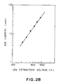
- Fig. 28 illustrates the ion extraction characteristics of the first embodiment of the ion source.
- the ion extraction voltage plotted along the abscissa represents a relative difference in voltage between the plasma generating chamber 14 and the grid 39A.
- An ion source can be constructed by incorporating an ion extraction mechanism with a plasma generating chamber to which a vacuum waveguide surrounded with a yoke as shown in Fig. 9.
- an ion source can be obtained by incorporating the ion extraction mechanism to the lower end of the plasma generating chamber and by utilizing such ion sources, the thin film forming apparatuses can be constructed.
- Fig. 29 illustrates a thin film forming apparatus incorporating a second embodiment of the ion source in accordance with the present invention.
- this embodiment of the ion source is such that the ion extraction mechanism 39 is attached to the lower end of the plasma generating chamber 14 of the thin film froming apparatus shown in Fig. 15.
- the power supplies 39C and 39D are not shown.
- the arrangement of the targets and the electromagnets are substantially similar to that of the film forming apparatus described above with reference to Fig. 15. It follows therefore that, as described above, high-density plasma can be generated in the plasma generating chamber 14 and the ions in plasma can be efficiently extracted as an ion beam.
- the discharge characteristics of this embodiment of the ion source is substantially similar to that shown in Fig. 17.
- the ion extraction characteristics of the second embodiment of the ion source were better than that of the first embodiment shown in Fig. 26.
- the thin Al films were formed over the surfaces of the substrates which were mounted on the substrate holder 24 which was not heated. In other words, the films were formed at room temperature.
- the experimental results showed that each Al film was continuously formed at a deposition rate ranging from 1 - 10 nm/min in a stable and efficient manner for a long period of time.
- planar target 35 can be replaced by a cylindrical or tubular target.
- the apparatuses for generating plasma by introducing the microwave into the plasma generating chamber in the direction perpendicular to the axis of plasma; that is, embodiments described above with reference to Figs. 18, 19, 20 and 21, respectively, and their modifications can be converted into an ion source by incorporating the ion extraction mechanism at the lower end of the plasma generating chamber of each apparatus. Further, the microwave can be introduced in the direction relatively inclined with the axial direction of the plasma to be generated. Furthermore, by utilizing such ion sources, the thin film forming apparatuses can be constructed.
- an anode may be used in order to control the plasma potential. That is, for instance, a cylindrical anode is disposed within the plasma generating chamber and is applied with a voltage so that the potential of plasma can be controlled, and consequently the ion extraction efficiency of the ion extraction mechanism can be further enhanced. Furthermore, the energy of ions can be controlled in response to the voltage applied to the anode.
- the ion extraction mechanism 39 has been described as comprising two perforated grids, but it is to be understood that it may comprises only one perforated grid. That is, when the perforated grid 39A on the side of plasma is eliminated and only one perforated accelerating grid is used, even though the latter grid is subjected to the direct bombardment of ions, but the ion extraction efficiency is higher than that of the ion extraction mechanism 39 consisting of two grids 39A and 39B in the low energy range less than 200 eV.
- the thin film forming apparatuses in accordance with the present invention can generate microwave-plasma by ECR, and plasma thus generated is utilized in sputtering so that the continuous formation of thin films can be realized at low temperatures in a low gas pressure at a high efficiency in a stable manner for a long period of time regulardless of the electric conductivity and the thickness of a film being grown.
- the energy of particles can be controlled over a wide range from a few eV to several keV and highly active plasma is utilized, hence a high quality thin film almost free from damage can be continuously formed at a high deposition rate in a highly stabilized manner over a substrate which is maintained at a relatively low temperature.
- the targets are so arranged and the magnetic field is so produced that high-energy electrons are reflected back into plasma, whereby the formation of a thin film at a high deposition rate can be realized.
- the vacuum waveguide When the vacuum waveguide is connected to the plasma generating chamber in the direction perpendicular to the direction of the magnetic flux, the propagation of plasma into the vacuum waveguide can be inhibited. As a result the contamination of the microwave introduction window due to the adherence of an electrically conductive film thereto can be prevented, so that the reflection of the microwave can be neglected and therefore an electrically conductive film as a metal can be continuously formed in a stable manner for a long period of time.
- the plasma generating chamber to which a vacuum waveguide is connected in the direction inclined to the magnetic flux, is usable in the ion source according to the present invention.
- the ion sources in accordance with the present invention utilizes microwave plasma generated by ECR for sputtering, so that the ion extraction can be realized in a low pressure gas at a high efficiency. It follows therefore that regardless of kinds of ions and the conductivity and thickness of a film being grown by the deposition of the sputtered particles, the ions can be extracted continuously in a stable manner for a long period of time.
- a thin film forming apparatus comprises a plasma generating chamber (14) into which is introduced a gas to generate plasma therein; a microwave introduction window (16) connected to the plasma generating chamber (14) for introducing the microwave into the latter, a first target (17) and a second target (18) made of materials to be sputtered and disposed at both end portions of interior of the plasma generating chamber (14), respectively, at least one of the first and second targets (17,18) being in the form of a tube, at least one power supply (19) for applying a negative voltage to the first and second targets (17,18), magnetic field producing means (21) for producing the magnetic field and the magnetic flux leaving one of the first and second targets (17,18) and entering the other, and a specimen chamber (23) communicated to the plasma generating chamber (14) and having a substrate holder (24) installed therein.
- High-density ECR plasma generated within the plasma generating chamber (14) sputters the targets (17,18) so that the sputtered target materials are deposited on a substrate (25) to form a thin film. It is also possible to extract ions in plasma by incorporating an ion extraction mechanism at the lower end of the plasma generating chamber.
Landscapes
- Chemical & Material Sciences (AREA)
- Engineering & Computer Science (AREA)
- Physics & Mathematics (AREA)
- Plasma & Fusion (AREA)
- Analytical Chemistry (AREA)
- Chemical Kinetics & Catalysis (AREA)
- Materials Engineering (AREA)
- Mechanical Engineering (AREA)
- Metallurgy (AREA)
- Organic Chemistry (AREA)
- Combustion & Propulsion (AREA)
- Physical Vapour Deposition (AREA)
Claims (15)
- Plasmaerzeugungsgerät, gekennzeichnet durch
eine Plasmaerzeugungskammer (14), in die ein Gas zum Erzeugen von Plasma eingeleitet wird, wobei die Plasmaerzeugungskammer derart gestaltet ist, daß das Plasma durch Mikrowellen-Elektronenzyklotron-Resonanzentladung erzeugt wird,
ein Mikrowellen-Einleitungsfenster (16) zum Einleiten der Mikrowelle in die Plasmaerzeugungskammer,
ein erstes Target (17) und ein zweites Target (18, 35), die jeweils an den beiden Endabschnitten des Inneren der Plasmaerzeugungskammer (14) angeordnet sind und die aus zu zerstäubenden Materialien bestehen, wobei das erste und/oder das zweite Target die Form eines Rohres hat, dessen Innenfläche die Prallfläche ist,
mindestens eine Spannungsquelle (19, 20; 33, 34) zum Anlegen einer Spannung an das erste und das zweite Target (17, 18; 35, 36), die in bezug auf diejenige der Plasmaerzeugungskammer negativ ist, und
eine Magnetfeld-Erzeugungsvorrichtung (21), die ein Magnetfeld erzeugt, wobei der magnetische Fluß aus dem ersten oder dem zweiten Target austritt und in das andere Target eintritt. - Ionenquelle mit einem Plasmaerzeugungsgerät gemäß Patentanspruch 1 und einem Ionenauszugsmechanismus (39), der an einem Ende der Plasmaerzeugungskammer angeordnet ist.
- Ionenquelle nach Anspruch 2, dadurch gekennzeichnet, daß die Plasmaerzeugungskammer (14) derart gestaltet ist, daß das Plasma durch Mikrowellen-Elektronenzyklotron-Resonanzentladung erzeugt wird.
- Ionenquelle nach Anspruch 2, dadurch gekennzeichnet, daß die Mikrowelle in die Plasmaerzeugungskammer (14) in der Richtung der Achse des Plasmas eingeleitet wird und das Mikrowellen-Einleitfenster (16) über einen Vakuum-Hohlleiter (15) mit der Plasmaerzeugungskammer verbunden ist, der von einem Joch derart umgeben ist, daß das von der Magnetfeld-Erzeugungsvorrichtung (21) erzeugte Magnetfeld aufgenommen wird, die magnetische Feldstärke in dem Vakuum-Hohlleiter (15) verringert ist und die magnetische Feldstärke sich an der Grenze zwischen dem Vakuum-Hohlleiter (15) und der Plasmaerzeugungskammer (14) deutlich ändert.
- Ionenquelle nach Anspruch 2, dadurch gekennzeichnet, daß die Richtung der Mikrowelleneinleitung nicht zu der Achse des zu erzeugenden Plasmas parallel ist.
- Ionenquelle nach Anspruch 2, dadurch gekennzeichnet, daß das Mikrowellen-Einleitfenster an einer Stelle liegt, die nicht direkt von dem ersten und dem zweiten Target (17, 18; 35, 36) her gesehen werden kann.
- Ionenquelle nach Anspruch 2, dadurch gekennzeichnet, daß das rohrförmige Target die Form eines polygonalen Rohres hat.
- Ionenquelle nach Anspruch 2, dadurch gekennzeichnet, daß das erste oder das zweite Target die Form eines Rohres hat, während das andere die Form einer flachen Platte hat.
- Ionenquelle nach Anspruch 2, dadurch gekennzeichnet, daß das erste und das zweite Target beide die Form eines Rohres (17, 36) haben.
- Ionenquelle nach Anspruch 9, dadurch gekennzeichnet, daß mit den beiden Enden der Plasmaerzeugungskammer (14) jeweils Probenkammern (23, 23c) in Verbindung stehen.
- Ionenquelle nach Anspruch 2, dadurch gekennzeichnet, daß das erste und das zweite Target jeweils die Endabschnitte eines Targets (38) in der Form eines Rohres sind (Fig. 19).
- Ionenquelle nach Anspruch 2, dadurch gekennzeichnet, daß in der Nähe des Substrathalters (24) eine Hilfsmagnetfeld-Erzeugungsvorrichtung (28) angeordnet ist, um das von der Magnetfeld-Erzeugungsvorrichtung erzeugte Magnetfeld zu steuern.
- Ionenquelle nach Anspruch 2, dadurch gekennzeichnet, daß der Ionenauszugsmechanismus (39) zwei durchlöcherte Gitter (39A, 39B) aufweist.
- Ionenquelle nach Anspruch 2, dadurch gekennzeichnet, daß der Ionenauszugsmechanismus (39) ein einziges durchlöchertes Gitter aufweist.
- Dünnfilmformungsgerät, das eine Ionenquelle gemäß einem der Ansprüche 2 bis 14 mit oder ohne den Auszugsmechanismus (39) und eine Probenkammer (23) aufweist, die an die Plasmaerzeugungskammer angeschlossen ist und in die ein Substrathalter (24) eingebaut ist.
Applications Claiming Priority (8)
| Application Number | Priority Date | Filing Date | Title |
|---|---|---|---|
| JP63025602A JP2602267B2 (ja) | 1988-02-08 | 1988-02-08 | プラズマ生成装置およびプラズマを利用した薄膜形成装置 |
| JP25602/88 | 1988-02-08 | ||
| JP25601/88 | 1988-02-08 | ||
| JP63025601A JP2552697B2 (ja) | 1988-02-08 | 1988-02-08 | イオン源 |
| JP44214/88 | 1988-02-29 | ||
| JP63044215A JP2552701B2 (ja) | 1988-02-29 | 1988-02-29 | イオン源 |
| JP44215/88 | 1988-02-29 | ||
| JP63044214A JP2552700B2 (ja) | 1988-02-29 | 1988-02-29 | プラズマ生成装置およびプラズマを利用した薄膜形成装置 |
Publications (3)
| Publication Number | Publication Date |
|---|---|
| EP0328076A2 EP0328076A2 (de) | 1989-08-16 |
| EP0328076A3 EP0328076A3 (en) | 1990-08-22 |
| EP0328076B1 true EP0328076B1 (de) | 1994-05-04 |
Family
ID=27458348
Family Applications (1)
| Application Number | Title | Priority Date | Filing Date |
|---|---|---|---|
| EP89102164A Expired - Lifetime EP0328076B1 (de) | 1988-02-08 | 1989-02-08 | Gerät zur Bildung dünner Schichten und durch Mikrowellen-Zerstäubung arbeitende Ionenquelle |
Country Status (4)
| Country | Link |
|---|---|
| US (1) | US4911814A (de) |
| EP (1) | EP0328076B1 (de) |
| KR (1) | KR920003790B1 (de) |
| DE (1) | DE68915014T2 (de) |
Families Citing this family (56)
| Publication number | Priority date | Publication date | Assignee | Title |
|---|---|---|---|---|
| US5022977A (en) * | 1986-09-29 | 1991-06-11 | Nippon Telegraph And Telephone Corporation | Ion generation apparatus and thin film forming apparatus and ion source utilizing the ion generation apparatus |
| US5053678A (en) * | 1988-03-16 | 1991-10-01 | Hitachi, Ltd. | Microwave ion source |
| EP0401622B1 (de) * | 1989-06-05 | 1995-08-23 | Balzers Aktiengesellschaft | Verfahren zum Kühlen von Targets sowie Kühleinrichtung für Targets |
| JP2573702B2 (ja) * | 1989-12-19 | 1997-01-22 | 三菱電機株式会社 | プラズマエッチング装置 |
| US5142198A (en) * | 1989-12-21 | 1992-08-25 | Applied Science And Technology, Inc. | Microwave reactive gas discharge device |
| IT1238337B (it) * | 1990-01-23 | 1993-07-12 | Cons Ric Microelettronica | Dispositivo per la ionizzazione di metalli ad alta temperatura di fusione, utilizzabile su impiantatori ionici del tipo impiegante sorgenti di ioni di tipo freeman o assimilabili |
| KR930004713B1 (ko) * | 1990-06-18 | 1993-06-03 | 삼성전자 주식회사 | 변조방식을 이용한 플라즈마 발생장치 및 방법 |
| US5274306A (en) * | 1990-08-31 | 1993-12-28 | Kaufman & Robinson, Inc. | Capacitively coupled radiofrequency plasma source |
| US5178739A (en) * | 1990-10-31 | 1993-01-12 | International Business Machines Corporation | Apparatus for depositing material into high aspect ratio holes |
| US5198725A (en) * | 1991-07-12 | 1993-03-30 | Lam Research Corporation | Method of producing flat ecr layer in microwave plasma device and apparatus therefor |
| US5256938A (en) * | 1992-02-28 | 1993-10-26 | The United States Of America As Represented By The Department Of Energy | ECR ion source with electron gun |
| US5302266A (en) * | 1992-03-20 | 1994-04-12 | International Business Machines Corporation | Method and apparatus for filing high aspect patterns with metal |
| WO1995000677A1 (en) * | 1993-06-17 | 1995-01-05 | Deposition Sciences, Inc. | Sputtering device |
| JPH07268622A (ja) * | 1994-03-01 | 1995-10-17 | Applied Sci & Technol Inc | マイクロ波プラズマ付着源 |
| US6238533B1 (en) * | 1995-08-07 | 2001-05-29 | Applied Materials, Inc. | Integrated PVD system for aluminum hole filling using ionized metal adhesion layer |
| US5962923A (en) * | 1995-08-07 | 1999-10-05 | Applied Materials, Inc. | Semiconductor device having a low thermal budget metal filling and planarization of contacts, vias and trenches |
| DE19540794A1 (de) * | 1995-11-02 | 1997-05-07 | Leybold Ag | Vorrichtung zum Beschichten eines Substrats von einem elektrisch leitfähigen Target |
| EP0799903A3 (de) | 1996-04-05 | 1999-11-17 | Applied Materials, Inc. | Verfahren zum Sputtern eines Metalls auf ein Substrat und Vorrichtung zur Behandlung von Halbleitern |
| JPH10144668A (ja) * | 1996-11-14 | 1998-05-29 | Tokyo Electron Ltd | プラズマ処理方法 |
| JP3650248B2 (ja) * | 1997-03-19 | 2005-05-18 | 東京エレクトロン株式会社 | プラズマ処理装置 |
| US20010049196A1 (en) * | 1997-09-09 | 2001-12-06 | Roger Patrick | Apparatus for improving etch uniformity and methods therefor |
| US6565717B1 (en) | 1997-09-15 | 2003-05-20 | Applied Materials, Inc. | Apparatus for sputtering ionized material in a medium to high density plasma |
| US20050272254A1 (en) * | 1997-11-26 | 2005-12-08 | Applied Materials, Inc. | Method of depositing low resistivity barrier layers for copper interconnects |
| WO1999027579A1 (en) * | 1997-11-26 | 1999-06-03 | Applied Materials, Inc. | Damage-free sculptured coating deposition |
| US7253109B2 (en) * | 1997-11-26 | 2007-08-07 | Applied Materials, Inc. | Method of depositing a tantalum nitride/tantalum diffusion barrier layer system |
| FR2774251B1 (fr) * | 1998-01-26 | 2000-02-25 | Commissariat Energie Atomique | Source a plasma micro-onde lineaire en aimants permanents |
| US6274459B1 (en) | 1998-02-17 | 2001-08-14 | Silicon Genesis Corporation | Method for non mass selected ion implant profile control |
| US6197165B1 (en) | 1998-05-06 | 2001-03-06 | Tokyo Electron Limited | Method and apparatus for ionized physical vapor deposition |
| US6287435B1 (en) | 1998-05-06 | 2001-09-11 | Tokyo Electron Limited | Method and apparatus for ionized physical vapor deposition |
| US6080287A (en) * | 1998-05-06 | 2000-06-27 | Tokyo Electron Limited | Method and apparatus for ionized physical vapor deposition |
| JP3608416B2 (ja) * | 1999-02-02 | 2005-01-12 | 日新電機株式会社 | プラズマ源 |
| JP4351755B2 (ja) * | 1999-03-12 | 2009-10-28 | キヤノンアネルバ株式会社 | 薄膜作成方法および薄膜作成装置 |
| US6458723B1 (en) | 1999-06-24 | 2002-10-01 | Silicon Genesis Corporation | High temperature implant apparatus |
| DE10060002B4 (de) * | 1999-12-07 | 2016-01-28 | Komatsu Ltd. | Vorrichtung zur Oberflächenbehandlung |
| US20030066486A1 (en) * | 2001-08-30 | 2003-04-10 | Applied Materials, Inc. | Microwave heat shield for plasma chamber |
| JP4166455B2 (ja) * | 2001-10-01 | 2008-10-15 | 株式会社半導体エネルギー研究所 | 偏光フィルム及び発光装置 |
| JP4024510B2 (ja) * | 2001-10-10 | 2007-12-19 | 株式会社半導体エネルギー研究所 | 記録媒体、および基材 |
| US7527713B2 (en) * | 2004-05-26 | 2009-05-05 | Applied Materials, Inc. | Variable quadruple electromagnet array in plasma processing |
| US7686926B2 (en) * | 2004-05-26 | 2010-03-30 | Applied Materials, Inc. | Multi-step process for forming a metal barrier in a sputter reactor |
| US20060081467A1 (en) * | 2004-10-15 | 2006-04-20 | Makoto Nagashima | Systems and methods for magnetron deposition |
| GB2419894B (en) * | 2004-10-22 | 2009-08-26 | Plasma Quest Ltd | Sputtering system |
| US20070205096A1 (en) * | 2006-03-06 | 2007-09-06 | Makoto Nagashima | Magnetron based wafer processing |
| US8454810B2 (en) | 2006-07-14 | 2013-06-04 | 4D-S Pty Ltd. | Dual hexagonal shaped plasma source |
| US8308915B2 (en) * | 2006-09-14 | 2012-11-13 | 4D-S Pty Ltd. | Systems and methods for magnetron deposition |
| US20080196243A1 (en) * | 2006-11-14 | 2008-08-21 | Texas Instruments Deutschland Gnbh | Device for Coupling Electromagnetic Radiation from a Source into a Microwave Chamber |
| US20090194414A1 (en) * | 2008-01-31 | 2009-08-06 | Nolander Ira G | Modified sputtering target and deposition components, methods of production and uses thereof |
| EE200900010A (et) * | 2008-02-13 | 2009-10-15 | Krimanov Aleksander | Ioonide voolu juhtimise meetod ja seade |
| US7777151B2 (en) * | 2008-02-14 | 2010-08-17 | Adventix Technologies Inc. | Portable plasma sterilizer |
| TWI393798B (zh) * | 2009-07-17 | 2013-04-21 | 愛發科股份有限公司 | 成膜裝置及成膜方法 |
| US9624570B2 (en) * | 2012-02-09 | 2017-04-18 | Fluxion Inc. | Compact, filtered ion source |
| US9297063B2 (en) * | 2012-04-26 | 2016-03-29 | Varian Semiconductor Equipment Associates, Inc. | Plasma potential modulated ion implantation system |
| KR20140019577A (ko) * | 2012-08-06 | 2014-02-17 | 삼성디스플레이 주식회사 | 박막 증착 장치 및 이를 이용한 박막 증착 방법 |
| KR102235442B1 (ko) * | 2014-06-30 | 2021-04-01 | 삼성전자주식회사 | 스퍼터링 장치 및 방법 |
| US10128083B2 (en) * | 2016-06-01 | 2018-11-13 | Vebco Instruments Inc. | Ion sources and methods for generating ion beams with controllable ion current density distributions over large treatment areas |
| DE102018211649A1 (de) * | 2018-07-12 | 2020-01-16 | Robert Bosch Gmbh | Verfahren zum Beschichten wenigstens eines metallischen Bauteils |
| JP7245661B2 (ja) * | 2019-01-30 | 2023-03-24 | Jswアフティ株式会社 | ターゲットおよび成膜装置並びに成膜対象物の製造方法 |
Family Cites Families (8)
| Publication number | Priority date | Publication date | Assignee | Title |
|---|---|---|---|---|
| JPS6050167A (ja) * | 1983-08-26 | 1985-03-19 | Nippon Telegr & Teleph Corp <Ntt> | プラズマ付着装置 |
| EP0103461B1 (de) * | 1982-09-10 | 1988-11-17 | Nippon Telegraph And Telephone Corporation | Vorrichtung und Verfahren zum Auftragen mittels Plasma |
| EP0106497B1 (de) * | 1982-09-10 | 1988-06-01 | Nippon Telegraph And Telephone Corporation | Ionenflutgerät |
| CH659484A5 (de) * | 1984-04-19 | 1987-01-30 | Balzers Hochvakuum | Anordnung zur beschichtung von substraten mittels kathodenzerstaeubung. |
| JPH07107189B2 (ja) * | 1986-03-24 | 1995-11-15 | 日本電信電話株式会社 | 薄膜形成装置 |
| JPH0689464B2 (ja) * | 1986-03-26 | 1994-11-09 | 日本電信電話株式会社 | イオン源 |
| DE3774098D1 (de) * | 1986-12-29 | 1991-11-28 | Sumitomo Metal Ind | Plasmageraet. |
| JPH066786B2 (ja) * | 1987-03-17 | 1994-01-26 | 日本電信電話株式会社 | 薄膜形成装置 |
-
1989
- 1989-02-07 US US07/307,312 patent/US4911814A/en not_active Expired - Lifetime
- 1989-02-08 KR KR8901399A patent/KR920003790B1/ko not_active Expired
- 1989-02-08 DE DE68915014T patent/DE68915014T2/de not_active Expired - Lifetime
- 1989-02-08 EP EP89102164A patent/EP0328076B1/de not_active Expired - Lifetime
Also Published As
| Publication number | Publication date |
|---|---|
| EP0328076A2 (de) | 1989-08-16 |
| DE68915014D1 (de) | 1994-06-09 |
| US4911814A (en) | 1990-03-27 |
| DE68915014T2 (de) | 1994-12-08 |
| EP0328076A3 (en) | 1990-08-22 |
| KR890013820A (ko) | 1989-09-26 |
| KR920003790B1 (en) | 1992-05-14 |
Similar Documents
| Publication | Publication Date | Title |
|---|---|---|
| EP0328076B1 (de) | Gerät zur Bildung dünner Schichten und durch Mikrowellen-Zerstäubung arbeitende Ionenquelle | |
| EP0328033B1 (de) | Anlage zur Erzeugung von Dünnschichten und Ionenquelle unter Anwendung von Plasmazerstäubung | |
| US5022977A (en) | Ion generation apparatus and thin film forming apparatus and ion source utilizing the ion generation apparatus | |
| EP1554412B1 (de) | Plasmaunterstützte chemische Gasphasenabscheidung Vorrichtung | |
| EP0285668B1 (de) | Vorrichtung zur bildung dünner folien | |
| AU746645C (en) | Method and apparatus for deposition of biaxially textured coatings | |
| US4094764A (en) | Device for cathodic sputtering at a high deposition rate | |
| US5122252A (en) | Arrangement for the coating of substrates | |
| US4610770A (en) | Method and apparatus for sputtering | |
| US4492620A (en) | Plasma deposition method and apparatus | |
| US5234560A (en) | Method and device for sputtering of films | |
| US6579421B1 (en) | Transverse magnetic field for ionized sputter deposition | |
| CN1606795A (zh) | 用于等离子体溅射的与旋转磁控管结合的磁体阵列 | |
| JPH0816266B2 (ja) | 高アスペクト比の穴に材料を付着させる装置 | |
| US5369337A (en) | DC or HF ion source | |
| EP0413291B1 (de) | Verfahren und Vorrichtung zum Sputterauftragen von Filmen | |
| JPH0641739A (ja) | 高真空・高速イオン処理装置 | |
| JP2552701B2 (ja) | イオン源 | |
| JPS62224686A (ja) | イオン源 | |
| JP2552697B2 (ja) | イオン源 | |
| JP2566602B2 (ja) | イオン源 | |
| JP2602267B2 (ja) | プラズマ生成装置およびプラズマを利用した薄膜形成装置 | |
| Hoshi et al. | High‐rate, low‐temperature sputtering method of facing‐targets type and its application for deposition of magnetic films | |
| JP2835383B2 (ja) | スパッタ型イオン源 | |
| JPH0721993B2 (ja) | スパッタ型イオン源 |
Legal Events
| Date | Code | Title | Description |
|---|---|---|---|
| PUAI | Public reference made under article 153(3) epc to a published international application that has entered the european phase |
Free format text: ORIGINAL CODE: 0009012 |
|
| 17P | Request for examination filed |
Effective date: 19890208 |
|
| AK | Designated contracting states |
Kind code of ref document: A2 Designated state(s): DE FR GB |
|
| PUAL | Search report despatched |
Free format text: ORIGINAL CODE: 0009013 |
|
| AK | Designated contracting states |
Kind code of ref document: A3 Designated state(s): DE FR GB |
|
| 17Q | First examination report despatched |
Effective date: 19930115 |
|
| GRAA | (expected) grant |
Free format text: ORIGINAL CODE: 0009210 |
|
| AK | Designated contracting states |
Kind code of ref document: B1 Designated state(s): DE FR GB |
|
| REF | Corresponds to: |
Ref document number: 68915014 Country of ref document: DE Date of ref document: 19940609 |
|
| ET | Fr: translation filed | ||
| PLBE | No opposition filed within time limit |
Free format text: ORIGINAL CODE: 0009261 |
|
| STAA | Information on the status of an ep patent application or granted ep patent |
Free format text: STATUS: NO OPPOSITION FILED WITHIN TIME LIMIT |
|
| 26N | No opposition filed | ||
| REG | Reference to a national code |
Ref country code: FR Ref legal event code: CA |
|
| REG | Reference to a national code |
Ref country code: GB Ref legal event code: IF02 |
|
| PGFP | Annual fee paid to national office [announced via postgrant information from national office to epo] |
Ref country code: GB Payment date: 20080222 Year of fee payment: 20 |
|
| PGFP | Annual fee paid to national office [announced via postgrant information from national office to epo] |
Ref country code: DE Payment date: 20080320 Year of fee payment: 20 Ref country code: FR Payment date: 20080219 Year of fee payment: 20 |
|
| REG | Reference to a national code |
Ref country code: GB Ref legal event code: PE20 Expiry date: 20090207 |
|
| PG25 | Lapsed in a contracting state [announced via postgrant information from national office to epo] |
Ref country code: GB Free format text: LAPSE BECAUSE OF EXPIRATION OF PROTECTION Effective date: 20090207 |