EP0328039A2 - Dispositif pour enlever les couches de papier intercalaires - Google Patents
Dispositif pour enlever les couches de papier intercalaires Download PDFInfo
- Publication number
- EP0328039A2 EP0328039A2 EP89102067A EP89102067A EP0328039A2 EP 0328039 A2 EP0328039 A2 EP 0328039A2 EP 89102067 A EP89102067 A EP 89102067A EP 89102067 A EP89102067 A EP 89102067A EP 0328039 A2 EP0328039 A2 EP 0328039A2
- Authority
- EP
- European Patent Office
- Prior art keywords
- gripping
- parts
- arm
- paper
- pressing
- Prior art date
- Legal status (The legal status is an assumption and is not a legal conclusion. Google has not performed a legal analysis and makes no representation as to the accuracy of the status listed.)
- Withdrawn
Links
Images


Classifications
-
- G—PHYSICS
- G03—PHOTOGRAPHY; CINEMATOGRAPHY; ANALOGOUS TECHNIQUES USING WAVES OTHER THAN OPTICAL WAVES; ELECTROGRAPHY; HOLOGRAPHY
- G03F—PHOTOMECHANICAL PRODUCTION OF TEXTURED OR PATTERNED SURFACES, e.g. FOR PRINTING, FOR PROCESSING OF SEMICONDUCTOR DEVICES; MATERIALS THEREFOR; ORIGINALS THEREFOR; APPARATUS SPECIALLY ADAPTED THEREFOR
- G03F9/00—Registration or positioning of originals, masks, frames, photographic sheets or textured or patterned surfaces, e.g. automatically
-
- B—PERFORMING OPERATIONS; TRANSPORTING
- B65—CONVEYING; PACKING; STORING; HANDLING THIN OR FILAMENTARY MATERIAL
- B65H—HANDLING THIN OR FILAMENTARY MATERIAL, e.g. SHEETS, WEBS, CABLES
- B65H3/00—Separating articles from piles
- B65H3/02—Separating articles from piles using friction forces between articles and separator
Definitions
- the invention relates to a device arranged on a punching device in the production of register-containing offset plates for removing the uppermost interleaving paper from offset plates stacked on top of one another.
- the intermediate layer paper inserted between two offset plates in order to protect the sensitive plate surface of offset plates must be reliably removed when punching the offset plates in a fully automatic machine before being transported to the punching section. This means that the remaining paper lying on the next offset plate must be removed from a stack of plates after the top offset plate has been removed.
- the invention is concerned with the problem of designing a device of the type mentioned at the outset in such a way that, on the one hand, an operationally reliable removal of the intermediate layer papers is ensured and, on the other hand, relatively high working speeds are possible in the downstream punching device.
- two fingers that can be moved relative to one another are brought to the stack of the offset plates, at least one finger is brought into contact with the intermediate layer paper, due to the friction of the soft rubber part of the finger, part of the intermediate layer paper is folded or pushed together and between the two Finger pressed so that the interleaving paper can be removed from the stack of offset plates by moving the arm out.
- a pneumatic cylinder the piston rod of which can move the movable external gripping part between two positions, can serve as the drive for the relative movement of the two gripping parts.
- One of the gripping parts can be designed as a wheel and rotatably supported on the piston rod, it can also be a wobble Carry out movements so that turning the wheel ensures that the circumferential surface of the round rubber seal is evenly worn because the wheel is gradually turned a little after each gripping process.
- the inner gripping part can in principle be designed in the same way as the outer gripping part. However, it can also have the shape of a square disc, with a soft rubber part being at least on one edge.
- the two soft rubber parts have essentially the same radial extent, the rubber parts can be designed to be slightly flexible, or have such a shape that they can be easily deformed in the radial direction. It is important that one of the soft rubber parts can almost be placed on the paper without damaging the surface of the offset plate underneath, the other soft rubber part leading the interleaving paper into the interspace of the gripping parts by a relative movement and grasping it there.
- only the one gripping part comes into contact with the uppermost interlayer paper of the stack of offset plates.
- the other gripping part remains at a certain short distance from the uppermost interleaving paper. If the outer gripping part now sits on the interleaving paper and is moved in the direction of the other gripping part, the paper folds between the two gripping parts. With this type of removal of the liner paper, it is reliably achieved that the top liner paper can be gripped.
- the devices according to the invention can also be provided with a light barrier between the two Gripping parts is effective. If the paper is folded between the gripping parts, the light barrier reports this. If, on the other hand, no interleaving paper is detected due to any malfunction, the light barrier detects this malfunction and ensures that a new gripping process is carried out.
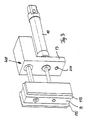
- a pressure medium cylinder is located inside the arm 10, and the arm 10 itself can also represent the housing of a pressure medium cylinder.
- a piston rod 12 of the Pressure cylinder can be retracted and extended via the control.
- a wheel 14 is arranged so that it can perform rotary movements with the piston rod 12 or relative to the piston rod 12.
- a square disc 13 is fixed to the arm 10. At the lower boundary there is a soft part 16, the lower extent of which corresponds to that of the wheel 14 or the round rubber seal 15.
- the gripping part 13 has a smaller radial extension with respect to the axis of the arm 10 than the gripping part 14.
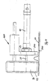
- the gripping part 14 When placed on a stack of offset plates, only the one arrives or the gripping members 115 engage the liner paper 20.
- the gripping part 14 shows two round rubber seals 115, which are attached to a gripping part 14 at a distance from one another.
- the round rubber parts 115 have been guided so that they have an extension in their lower area, the actual effective area, which is parallel to the axis of the arm 10. As a result, a line contact with the interleaving paper 20 is achieved, so that a secure gripping and clamping between the parts 13 and 14 is ensured.
- a light barrier device is shown at 200. If there is an intermediate layer paper 20 between the gripping parts 13 and 14 when moving them towards one another, this leads to differences in brightness, which are indicated by the light barrier 200.
- 400 designates a guide device for the gripping part 14 in relation to the gripping part 13. It is a common device for guiding moving parts.
Landscapes
- Engineering & Computer Science (AREA)
- Mechanical Engineering (AREA)
- Physics & Mathematics (AREA)
- General Physics & Mathematics (AREA)
- Sheets, Magazines, And Separation Thereof (AREA)
- Perforating, Stamping-Out Or Severing By Means Other Than Cutting (AREA)
Applications Claiming Priority (2)
| Application Number | Priority Date | Filing Date | Title |
|---|---|---|---|
| DE8801605U DE8801605U1 (de) | 1988-02-09 | 1988-02-09 | Vorrichtung zum Entfernen von Zwischenlagenpapier |
| DE8801605U | 1988-02-09 |
Publications (2)
| Publication Number | Publication Date |
|---|---|
| EP0328039A2 true EP0328039A2 (fr) | 1989-08-16 |
| EP0328039A3 EP0328039A3 (fr) | 1990-11-14 |
Family
ID=6820457
Family Applications (1)
| Application Number | Title | Priority Date | Filing Date |
|---|---|---|---|
| EP19890102067 Withdrawn EP0328039A3 (fr) | 1988-02-09 | 1989-02-07 | Dispositif pour enlever les couches de papier intercalaires |
Country Status (2)
| Country | Link |
|---|---|
| EP (1) | EP0328039A3 (fr) |
| DE (1) | DE8801605U1 (fr) |
Family Cites Families (2)
| Publication number | Priority date | Publication date | Assignee | Title |
|---|---|---|---|---|
| US4149798A (en) * | 1977-06-10 | 1979-04-17 | Eocom Corporation | Electrophotographic apparatus and method for producing printing masters |
| FR2543119A1 (fr) * | 1983-03-25 | 1984-09-28 | Letard Michel | Dispositif de prise d'une feuille superieure sur une pile de feuilles en matiere souple |
-
1988
- 1988-02-09 DE DE8801605U patent/DE8801605U1/de not_active Expired
-
1989
- 1989-02-07 EP EP19890102067 patent/EP0328039A3/fr not_active Withdrawn
Also Published As
| Publication number | Publication date |
|---|---|
| DE8801605U1 (de) | 1988-04-07 |
| EP0328039A3 (fr) | 1990-11-14 |
Similar Documents
| Publication | Publication Date | Title |
|---|---|---|
| DE2518779B2 (de) | Vorrichtung zum Abheben und Transportieren der jeweils obersten Lage aus lappigem Material von einem Stapel | |
| EP3290365B1 (fr) | Araignée à ventouses et procédé de disques de rectification du pulvérisage à disque élastique | |
| DE2217589C3 (de) | Beschickvorrichtung | |
| DE3808651C2 (de) | Vorrichtung zum Ergreifen und Vereinzeln des unteren Zuschnittes eines Stapels von Zuschnitten aus kaschiertem Papier o. dgl., insbesondere für eine Buchdeckenmaschine | |
| DE1113942B (de) | Vorrichtung zum Abnehmen von einzelnen Scheckformularen von einem Stapel | |
| DE4107196C2 (de) | Einrichtung zum Beseitigen gebrauchter Schablonen für eine Schablonendruckvorrichtung | |
| DE1275440B (de) | Vorrichtung zum automatischen Verschliessen einer vorstehenden Huelle an den Stirnseiten einer zu verpackenden Rolle | |
| DE2629634C3 (de) | Vorrichtung zum Vereinzeln von Münzen | |
| DE2328350C3 (de) | Verfahren und Vorrichtung zum Abheben einzelner Gewebelagen von einem Stapel | |
| DE102007033922A1 (de) | Abstechvorrichtung zum Abheben von Lagen blattartiger Materialstapel | |
| DE69704974T2 (de) | Apparat und Verfahren zur Benutzung in der Handhabung von Gegenständen in Form von Bogen | |
| DE69016418T2 (de) | Vorrichtung zum trennen einer kleinen anzahl von bögen. | |
| DE3510698C2 (fr) | ||
| DE2949745A1 (de) | Werkstuecktransportvorrichtung | |
| DE69504108T2 (de) | Vorrichtung zum heben eines randes des obersten blattes von einem blattstapel | |
| EP1083138A2 (fr) | Dispositif pour séparer des sacs vides | |
| DE1623178B2 (de) | Vorrichtung zum sortieren von muenzen und aehnlichen scheibenfoermigen gegenstaenden | |
| DE1266230B (de) | Vorrichtung zum einzelweisen Abheben von Scheiben, insbesondere Glasscheiben, von einem in etwa hochkant stehenden Stapel | |
| DE2211494A1 (de) | Blattzuführvorrichtung | |
| DE3134577A1 (de) | Elektrische schneidmaschine | |
| DE3703951C2 (de) | Wendevorrichtung für Papierstapel oder dergl. | |
| DE8801605U1 (de) | Vorrichtung zum Entfernen von Zwischenlagenpapier | |
| EP1264692A1 (fr) | Dispositif de nettoyage d'un cylindre d'une machine d'impression | |
| DE3211371C2 (de) | Vorrichtung zum Vereinzeln des jeweils obersten Blattes eines Stapels von blattförmigem Gut | |
| DE2641072A1 (de) | Vorrichtung zum absondern des jeweils untersten behaelters von den jeweils uebrigen behaeltern eines stapels aus ineinandergeschobenen behaeltern |
Legal Events
| Date | Code | Title | Description |
|---|---|---|---|
| PUAI | Public reference made under article 153(3) epc to a published international application that has entered the european phase |
Free format text: ORIGINAL CODE: 0009012 |
|
| AK | Designated contracting states |
Kind code of ref document: A2 Designated state(s): DE FR GB IT SE |
|
| PUAL | Search report despatched |
Free format text: ORIGINAL CODE: 0009013 |
|
| AK | Designated contracting states |
Kind code of ref document: A3 Designated state(s): DE FR GB IT SE |
|
| STAA | Information on the status of an ep patent application or granted ep patent |
Free format text: STATUS: THE APPLICATION IS DEEMED TO BE WITHDRAWN |
|
| 18D | Application deemed to be withdrawn |
Effective date: 19910515 |