EP0327037A2 - Plant protection sprayer - Google Patents
Plant protection sprayer Download PDFInfo
- Publication number
- EP0327037A2 EP0327037A2 EP89101665A EP89101665A EP0327037A2 EP 0327037 A2 EP0327037 A2 EP 0327037A2 EP 89101665 A EP89101665 A EP 89101665A EP 89101665 A EP89101665 A EP 89101665A EP 0327037 A2 EP0327037 A2 EP 0327037A2
- Authority
- EP
- European Patent Office
- Prior art keywords
- treatment
- discharge
- blower
- treatment zone
- air
- Prior art date
- Legal status (The legal status is an assumption and is not a legal conclusion. Google has not performed a legal analysis and makes no representation as to the accuracy of the status listed.)
- Granted
Links
Images


Classifications
-
- A—HUMAN NECESSITIES
- A01—AGRICULTURE; FORESTRY; ANIMAL HUSBANDRY; HUNTING; TRAPPING; FISHING
- A01M—CATCHING, TRAPPING OR SCARING OF ANIMALS; APPARATUS FOR THE DESTRUCTION OF NOXIOUS ANIMALS OR NOXIOUS PLANTS
- A01M7/00—Special adaptations or arrangements of liquid-spraying apparatus for purposes covered by this subclass
- A01M7/005—Special arrangements or adaptations of the spraying or distributing parts, e.g. adaptations or mounting of the spray booms, mounting of the nozzles, protection shields
- A01M7/0064—Protection shields
-
- A—HUMAN NECESSITIES
- A01—AGRICULTURE; FORESTRY; ANIMAL HUSBANDRY; HUNTING; TRAPPING; FISHING
- A01M—CATCHING, TRAPPING OR SCARING OF ANIMALS; APPARATUS FOR THE DESTRUCTION OF NOXIOUS ANIMALS OR NOXIOUS PLANTS
- A01M7/00—Special adaptations or arrangements of liquid-spraying apparatus for purposes covered by this subclass
- A01M7/0003—Atomisers or mist blowers
- A01M7/0014—Field atomisers, e.g. orchard atomisers, self-propelled, drawn or tractor-mounted
-
- A—HUMAN NECESSITIES
- A01—AGRICULTURE; FORESTRY; ANIMAL HUSBANDRY; HUNTING; TRAPPING; FISHING
- A01M—CATCHING, TRAPPING OR SCARING OF ANIMALS; APPARATUS FOR THE DESTRUCTION OF NOXIOUS ANIMALS OR NOXIOUS PLANTS
- A01M7/00—Special adaptations or arrangements of liquid-spraying apparatus for purposes covered by this subclass
- A01M7/005—Special arrangements or adaptations of the spraying or distributing parts, e.g. adaptations or mounting of the spray booms, mounting of the nozzles, protection shields
- A01M7/0064—Protection shields
- A01M7/0067—Protection shields with recovering of liquids
Definitions
- the invention relates to a crop protection discharge device.
- the discharge device according to the invention has at least one discharge unit for treatment medium, which is assigned a treatment zone.
- the discharge device is intended in particular for plant crops, such as agricultural row crops, and has, for example, at least one discharge unit to be moved over a row of plants.
- this discharge unit is intended, for example, to form a passage for the plants and can have discharge means for treatment media.
- Plant protection discharge devices of this type are used in particular for the treatment of high-stemmed plants, such as grapevines, and the media to be discharged can be used for plant protection, fertilization or similar treatments. It is usually desirable to apply the treatment agents in such a way that even in the leafy state, the plants are extensively covered or wetted over a large area or over the entire area, both on the plant stem and branches and on both sides of the leaves.
- a crop protection spraying device which has a separate cross-flow fan for a carrier air flow with associated nozzle unit for each treatment zone and, if necessary, a baffle with a collecting device for returning excess treatment medium at a distance on the other side of the treatment zone .
- This spraying device has numerous disadvantages, because in particular the return of the excess treatment medium is problematic, the design of the blower arrangement is complicated and the protection against spray which escapes freely and is therefore lost without plant wetting is inadequate.
- the invention is also based on the object of providing a discharge device for plant treatment media which ensures intensive application of the treatment agent at high working speed and nevertheless keeps this treatment agent as far as possible from the ground.
- means which remove or return or suck back the discharged, particle-like particles of the treatment medium, which are suspended in the air or in the air stream and which do not precipitate directly on the respective plant, and either at least partially feed it back to the discharge means immediately or, for example, store it temporarily after separation from the conveying air in order to be able to return the treatment medium that has been temporarily stored in this way to a suitable use.
- the suction device expediently has a suction air conveyor, namely, for example, a suction fan, which can also be used at the same time as a compressed air conveyor, for example for returning the sucked-back treatment medium to the discharge means or for other functional purposes of the discharge device.
- a separator for the treatment medium for example a cyclone
- a separator for the treatment medium can be provided in the flow path of the return suction device in front of the air conveyor, from which the treatment medium is then a buffer, for example the Main memory for the treatment medium is supplied. In this way, only a portion of the treatment medium sucked back can be passed directly through the air conveyor and the other portion can be separated.
- the task according to the invention can be achieved in an advantageous manner instead of the described designs, but in particular in addition to this, in that at least one boundary of the treatment zone or the passage is at least partially formed by an air curtain, which results, for example, from the fact that in the surface or plane of this delimitation from at least one delimitation edge, a flat air flow is generated which, if a vortex zone is provided, is expediently stronger than its air flow, but can continuously merge into this vortex zone or connect to this vortex zone.
- Such an air curtain is particularly suitable for the front and / or for the rear open end of the passage into which the plants enter or from which the plants derive Leave passage, but at least one lateral or a lower and / or upper boundary of the passage could also be at least partially formed by such an air curtain. It is particularly advantageous if the air curtain is formed by air from air nozzles lying opposite one another and directed approximately parallel or in alignment with one another, which can lie side by side in one or more rows.
- the suction openings of the suction device expediently take up the largest part of the area of one and / or the other lateral boundary or instead or in addition to this the upper boundary of the passage, the proportion of area of the suction opening between 50 and 90%, preferably at least or more than 70% of the associated limit can be.
- means which prevent the treatment medium from rebounding or splashing back from the boundaries of the passage.
- These means which practically form impact damping, can e.g. be formed by grids, blind-like slats or the like, which preferably cover or limit the respective suction opening of the back suction device.
- Separate nozzles or else the same air nozzles can be provided to form the air swirl zone on the one hand and the respective air curtain on the other hand.
- one and / or the other of these air nozzles are provided at the respective end of the passage, in particular one above the other or opposite one another, it being possible for them to be located directly adjacent to at least one suction opening.
- these air nozzles can be adjusted independently of one another with regard to the angular position of their nozzle axes with respect to the longitudinal center plane of the passage, for example, some air nozzles can be directed essentially towards the center of the passage or the vortex zone, while others of the air nozzles are oriented approximately at right angles to the longitudinal median plane mentioned and thereby form the associated air curtain.
- the air nozzles can also be arranged so as to be directionally adjustable in the vertical direction, so that an obliquely upward flow in the passage is supported in an advantageous manner.
- the discharge means of the device according to the invention can be designed for the discharge of dusty or powdery treatment agents or instead or additionally for the discharge of liquid treatment agents.
- the separator can also be designed accordingly for the separation of dry and / or liquid treatment media.
- the discharge means expediently have discharge nozzles which are provided approximately in the middle between the ends of the passage or between the air curtains, discharge nozzles being able to be provided one above the other and / or opposite one another on both sides of the passage. If the discharge nozzles lying on one side are directed against the opposite suction opening of the return suction device or if the respective discharge nozzles are located directly in front of the suction opening provided on the associated side, the return suction can be significantly improved.
- the discharge nozzles are also expediently adjustable in the vertical or longitudinal direction of the passage, the nozzle jets of the discharge nozzles and the swirling air nozzles advantageously meeting one another in the center of the passage or the swirl zone.
- the losses of treatment agent penetrating into the ground can also be substantially reduced in that the return suction device, which is used, for example, for fog suction back, essentially from its respective suction opening Lichen exclusively has upward flow paths within the associated discharge unit, which can be achieved, for example, in that a suction connection to be connected to the suction side of the air conveyor is located at the top of the passage.
- An axial and / or radial fan can be provided as the air conveyor or blower, depending on whether higher pressures and flow rates or higher air flow rates are desired.
- a flexible curtain can also be made, in the manner of self-swinging, door pairs made of flexible plastic material that are opposite one another in pairs be provided. If an excess air pressure is used within the passage, this pressure can be used to hold this curtain in a desired opening position against the restoring force acting on it.
- a particularly advantageous development of the subject matter of the invention is that means are provided in order to deflect a treatment stream, namely, for example, an air stream and / or a particle stream from the treatment medium in the region of the treatment zone, or in such a way that at least parts of the same treatment stream flow two or more times in the same direction or flow through the treatment zone and thus through the respective plant in different directions so that this plant is exposed to it several times in succession. If the treatment stream carries treatment medium, at least some of the particles not deposited during the previous passage through the plant are again directed towards the plant without intermediate separation and then only deposited on the plant, for example, from the opposite side or from an angle to it.
- means can be provided which, before, during or after the deflection, recharge the treatment stream with regard to its flow energy and its saturation with treatment medium, for example by supplying carrier air and / or treatment medium atomized again in particulate form.
- the flow paths of the treatment stream which do not adjoin one another over a deflection range of, for example, at most 90 ° to slightly more than 180 °, they are expediently approximately horizontally, namely, for example, one behind the other and at a distance from one another in particular so that there is a transverse distance between them , which is approximately in the order of magnitude of the associated flow cross-section extension of at least one of the treatment streams.
- a rotating one located approximately in the center of the treatment zone can be located in the space between the flow paths
- Vortex flow rollers are generated which, for example in the case of tall stem plants, rotates approximately around their upright stem axis or around a vortex axis which lies approximately in the associated axial plane of the row of plants.
- the charging of the treatment stream in the area of the respective flow path can expediently take place with a carrier air flow which at the same time forms an air curtain shielding against the escape of particles of the treatment medium on the outside of the associated flow path or on the associated, for example front end of the passage, which can also contribute to the further deflection of the treatment flow on this flow path in the direction of rotation of the deflection.
- means are further proposed with which the treatment stream is discharged in the area of the same side of the treatment zone, in particular in the area of the limitation associated with the blower, and is sucked back again, with the flow zone passing through the treatment zone freely and only through the direction of flow, through successive sections of the Treatment streams formed flow paths are assigned at least one redirection device with a redirection inlet, a deflection outlet located at a distance therefrom and possibly with bodies in the flow cross section of a separating or flow deflection device.
- Corresponding bodies can also be provided in the area of the back suction on the blower side, these bodies, for example formed by lamella sets, serving both to deflect the flow and also to separate out particles of the treatment medium which are too large and therefore difficult to convey by the carrier air flow. These are then expediently collected in a downward flow and either returned directly to the discharge nozzles and / or to a storage container.
- a channel-shaped, trough-shaped or shell-shaped bypass wall is provided, which faces the fan outlet and the fan inlet with its upright shell wall.
- At least one adjustable flow straightening body is provided in the area of at least one opening serving for the exit or the entrance of the treatment stream, whereby this opening is expediently provided on its front and / or rear upright boundary with respect to the running direction with a guide flap which can be pivoted about an upright axis.
- the opening can be widened like a funnel in the discharge or input direction, limited in parallel or narrowed like a funnel, and can be aligned differently by pivoting both flaps in the same direction.
- Such guide flaps are particularly advantageous at the blower outlet and at the deflection outlet or at the outlet adjacent to this for supplying the accelerator air flow and / or additional treatment medium
- the associated flap for example the blower outlet, also simultaneously shielding the adjacent opening forming the blower inlet from the blower outlet can, so that these two openings can lie essentially immediately adjacent or one behind the other.
- the discharge nozzles associated with the respective outlet can also be adjusted with respect to their nozzle orientation about an axis corresponding to the pivot axes of the guide flaps, wherein they are advantageously coupled to at least one of the respectively associated guide flaps in such a way that they are adjusted by themselves and thus at least with respect to this Guide valve always have the same orientation.
- blower e.g. Axial blowers, radial blowers, cross-flow or tangential blowers or the like.
- the discharge device for two or more treatment zones adjacent to one another has only a single blower, which is advantageously designed as an axial blower.
- This blower has an axial blower suction opening and a blower pressure opening lying radially outward and axially directly adjacent to it or to the blower rotor.
- the blower or blower rotor can be designed so that it does not take up the separated treatment medium and immediately releases it again with the carrier air flow it produces, finely distributed in particles.
- a collecting trough for possibly separated treatment medium can be provided below the blower or the fan runner, which is then returned from this collecting trough either directly to the discharge nozzles or to the storage tank.
- a guide housing is expediently provided for the reception of the blower, which then has the blower outlet or the blower outlet which is oriented differently from the pressure opening of the blower limited in relation to the blower suction opening differently oriented return suction inlet, which is also advantageously oriented approximately radially to the blower axis, so that the radially sucked back part of the treatment stream in the guide housing is deflected axially into the blower.
- the discharge device according to the invention can advantageously be dismantled and / or adjusted in such a way that different discharge methods can be carried out with it or that it can be easily attached to existing sprayers and can be transported or stored in a space-saving manner when not in use. It is particularly expedient if the limitation of the treatment zone opposite the blower, for example formed by the diversion device, by swiveling or the like. can be transferred into a position axially essentially adjoining the blower and very close to the periphery of the blower or the guide housing, in which the blower outlet or the associated discharge nozzles is then not limited, so that the treatment stream is then unhindered and unlimited in the usual way can be spread outdoors.
- the or a primary carrier air stream can also start from a boundary of the treatment zone lying at an angle or at a distance from the blower unit, namely, for example, from the opposite boundary, in which case the blower unit can form a bypass device for the treatment stream.
- a treatment stream can therefore be continuously circulated through two diverting devices, for example at a distance from one another, and always charged in the area of each diverting device with regard to its flow energy and / or its saturation with treatment medium in such a way that its flow energy or saturation is in the range of the treatment zone of freely crossing flow paths remains essentially constant.
- the limitation of the treatment zone opposite the blower unit is connected to the blower unit or to the blower pressure opening and / or to the blower suction opening via articulated, articulated or flexible duct extensions.
- the treatment flow directed against the opposite limitation can be aligned or promoted even better with regard to the diversion entrance.
- the channel bracket (s) are conveniently located at the top of the treatment zone and can be over suitable sealing elements, for example elastic, cuff-like rolling membranes, can be movably connected to the opposite boundary in such a way that they are simply detachably inserted from top to bottom.
- An upper cover of the treatment zone designed in the manner of a wall shield, can be formed in a simple manner by a flexible film or by a suspended or tensioned protective tarpaulin, which is expediently located directly on the underside of the duct bracket (s), at least partially attached to it, and therefore their joint movements are not affected in any way.
- the treatment zone advantageously with articulated brackets which also support or support the channel brackets or can be formed by these channel brackets, is in at least one area of their height, in particular in the upper and lower areas differently or separately adjustable.
- the boundary of the treatment zone opposite the blower unit can be arranged on the boom in its upper region about an approximately horizontal axis which is approximately parallel to the direction of rotation, so that it can be adjusted obliquely outwards or inwards.
- this limitation can thereby be pivoted into an approximately horizontal position above the plants, which makes it possible to move the discharge device over the plants in the manner of freely projecting arms in terms of their direction of rotation when they are turned.
- the discharge device or the like has a supporting frame.
- a motor vehicle for example a tractor or tractor
- the support frame project freely suspended from the chassis or can optionally be additionally provided with at least one support wheel running on the ground.
- the discharge device can expediently be raised and lowered, for example, in that it can be mounted with coupling members on the hydraulically raised and lowered, so-called three-point linkage of the motor vehicle. This results in a saddled arrangement of the discharge device on the tractor.
- Another arrangement and design or further development of the discharge device results from DE patent application P 37 38 518.6, to which reference is made for further details, features and effects.
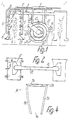
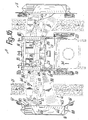
- the discharge device 1 shown in Figures 1 and 2 serves e.g. for treating row crops, the plants 2 of which are set in rows which are parallel to one another and at a distance from one another in such a way that it is possible to drive through between adjacent rows.
- the discharge device 1 has a discharge unit 3, wherein the two discharge units 3 can be of essentially the same design and can be arranged mirror-symmetrically to one another.
- Each discharge unit 3 forms a cabin-like passage or a treatment zone 4, which is open at the front and rear with respect to the direction of travel or running direction arrow 34 parallel to the rows, and which is also open on the underside, that is to say essentially U-shaped by lateral boundaries or walls 5, 6 and an upper wall 7 is limited.
- the cabin body thus formed is articulated at the end of a boom 8 of a supporting frame 9 which essentially only acts on its upper side, which lies between the rows of plants and on a suitable means of transportation consolidate it. With the boom 8, each discharge unit 3 can be separately cross-adjusted and thus adjusted to the row spacing.
- the discharge unit 3 has a discharge device 10 for dusts or treatment broth, which are essentially formed by discharge nozzles 11 on the inner sides of the side walls 5, 6.
- a discharge nozzles 11 are located one above the other approximately in the middle of the length of the passage 4 or of the cabin body and are directed towards the opposite side wall.
- the discharge nozzles 11 are connected to the pressure side of a liquid pressure pump 12 via suitable, flexible pressure lines guided at the top via the discharge units 3, it being possible for the discharge device 10 of each discharge unit 3 to be shut down or shut off independently of the other discharge unit, and for each discharge nozzle 11 is to be closed separately.
- the discharge nozzles 11 are distributed approximately uniformly over the entire height of the passage 4.
- Each discharge unit 3 is also assigned a separately shut-off or lockable compressed air device 13 which, in the region of each end of the passage 4 on the inside of both side walls 5, 6, has air nozzles 14, 15 which are substantially uniformly distributed one above the other, for example, wide mouth nozzles extending in the height direction , having. These air nozzles are connected to compressed air supply lines 16 outside the passage or the cabin body.
- the air nozzles 14, 15 can each serve both to form an air curtain at the associated end of the passage 4 and to generate a swirling air flow, in which the discharge device 10 lies approximately in the middle of the length of the passage 4 and extends over its entire height Injecting treatment agent.
- Separate air nozzles can also be provided for the air curtain and the eddy air flow be, for example the air nozzles for the vortex air flow in the area of the discharge nozzles 11 or closer to the center of the length of the passage 4 than the air nozzles for the respective air curtain.
- the underside of the passage 4 can also be delimited by an air curtain, expediently provided on both sides of the open underside of the cabin body, opposed air nozzles distributed over its length, which are preferably directed obliquely upwards at an angle of at most 45 °.
- each discharge unit 3 is assigned a separately shut-off or shut-off suction device 17 which serves to suck back the mist of the treatment medium suspended in the passage 4 in the air flow of the compressed air device 13.
- the suction device 17 in the upper wall 7 of the passage 4 has a suction opening 18 which extends over most of its length or between the air curtains and which connects to a blower via a suction line 19 connected laterally to the inner lateral wall 5 20 is connected.
- the blower 20 can, for example, be integrated with the discharge device 1 or its support frame 9, so that it can be removed with the entire discharge device 1 from a chassis, for example a tractor or a trailer.
- the blower 20 is arranged on the chassis 21 of a single-axle trailer, specifically at its rear end with a horizontal rotor axis or rotor axis parallel to the direction of travel, namely behind a container 22 which the chassis 21 carries and which carries a larger stock Treatment medium with the discharge device 1 is used.
- the blower 20 is driven, for example, just like the pressure pump 12, by means of the PTO shaft usually provided on tractors.
- the blower 20 usually provided on sprayers, the housing of which is open for axial suction and provided with radial air outlets on the circumference, is provided on the circumference with a circumferential or radial encapsulation 23, from which a branch line leads to the compressed air supply line 16.
- the suction side of the blower 20 located on the rear end face is likewise essentially closed and provided with a suction connection 24, to which a suction duct 25 leading to the suction line 19 is connected.
- a separator 26 is preferably connected to the sucking channel 25 at the suckback device 17, whereby this separator 26 has an outlet connected to the container 22 can have.
- the inner sides of the walls 5, 6, 7 are expedient with slats, sieve fabrics, nets or the like. regardless of whether or not they have suction openings, so that the treatment agent impinging on them does not tend to spray back like a reflection, but is initially absorbed or bound. In particular, if these absorbents are not in the area of a suction opening of the back suction device 17, the treatment medium will tend to drain downward when these absorbents are saturated.
- collecting channels 27 are provided with line connections, which extend over the entire length of the cabin, via which the collected treatment medium is sucked off through return lines, not shown, for example with the pressure pump 12 or an air jet pump (injector) and is expediently conveyed back into the container 22 and / or directly into the feed line to the discharge nozzles 11.
- each discharge unit 3 can only blow off the associated plants 2 separately, for example for the purpose of dedusting or removing excess treatment medium, in which case the air nozzles 14, 15 are set to a throttled blowing capacity.
- the particles removed from the plant 2 by this blowing off can be sucked off at the same time with the suction device 17 and, if necessary, returned in the manner described.
- at least two nozzle systems of discharge nozzles 11 are provided, which can be designed for the discharge of different treatment media. This can e.g. different treatment media are applied in different height zones, namely a different spraying agent in the fruit hanging zone of the plants 2 than in their leaf zone.
- At least one wall of the passage 4a is designed as a hollow wall, wherein at least the side walls 5a, 6a and / or the upper wall 7a are expediently designed as hollow walls.
- These double-walled hollow walls are designed essentially in the manner of a closed box section and are only open to the passage 4a on the associated inner wall where a suction opening 18a or an air nozzle, if applicable 14a, 15a or a discharge nozzle 11a is provided.
- suction openings 18a of the back suction device 17a can also be provided on one or both side walls 5a, 6a of the passage 4a, each suction opening being completely covered by one of the liquid-permeable absorption means mentioned.
- All walls 5a, 6a, 7a formed as hollow walls form a total of several, namely, for example, three chambers 28, 29, which are sealed against one another and each extend over all hollow walls. All chambers form flow channels of approximately the same thickness, but corresponding to the wall thickness, but different cross-section, since they differ extend to different lengths in the longitudinal direction of the passage 4a.
- the middle, largest and between the two side walls 5a, 6a through the upper wall 7a continuous chamber 28 is open to the passage 4a through the suction openings 18a and connected at the top of the upper wall 7a to a suction hood, which with a suction connection 30 for the Connection of the suction line is provided.
- a further, substantially smaller chamber 29 is provided, which is only in the area of the walls 5a, 6a having the air nozzles 14a, 15a or, like the chamber 28, can extend continuously over all walls.
- This chamber 29 is separated from the chamber 28 in each case by one or more suitable partition walls 31 which lie within the hollow wall and can serve to stiffen them.
- these chambers 29, which are also closed with respect to the collecting trough 27a are provided, for example, on the upper side of the cabin body with suitable connections for the compressed air supply line.
- the air nozzles 14a, 15a which can be pivoted about upright longitudinal axes into the inner parts of the associated walls 5a, 6a, are directly connected on the input side to the chambers 29, so that these form part of the compressed air supply.
- the discharge nozzles 11a are arranged one above the other on an upright manifold in the illustrated embodiment, which is located immediately in front of the associated suction opening 18a and penetrates the cabin body in the upper region to the outside, so that the pressure line for the treatment medium can be connected to the associated end of this manifold 32 .
- All connecting lines for the treatment medium, compressed air, suction and the like. are expediently detachable from the cabin body or from the discharge unit 3a, so that simple handling during assembly, in the event of malfunctions, for cleaning and for maintenance is ensured.
- the cabin body itself For cleaning the cabin body itself, it is expediently designed to be folded apart, for which purpose e.g. the side walls 5a, 6a in the upper region are connected to the upper wall 7a via hinge-like joints 33 or the walls 5a, 6a, 7a can be designed to be detachable from one another.
- the width of the passage 4a is also adjustable, although it is also conceivable to adjust the width by displaceably supporting the walls.
- a height adjustment of the passage 4a can also be expedient in order to be able to adapt the discharge unit 3a to the respective spatial conditions of the plants.
- an adjustability of the position of the discharge unit 3a or of the cabin body relative to the support frame is expediently provided, in particular with regard to the inclined position of the discharge unit 3a.
- one and the same discharge device can be used in several or at least two operating modes. For example, if the plants do not yet carry any leaves, it is desirable that the plant can be treated to the wet state, and in this case it is expedient if spraying agents are discharged with the discharge nozzles 11a essentially without air turbulence and in the process the passage 4a is shielded on its otherwise unlimited sides with air curtains. If the plants already have foliage, the treatment medium is expediently sprayed out in the manner described and distributed over the plant by air turbulence.
- this passage 4b can also be substantially continuously or progressively narrowed from top to bottom, the side walls 5b, 6b being flat and converging downward.
- one or both walls can also be slightly curved when viewed in the direction of travel, which gives them a much higher degree of dimensional stability.
- the upper wall 7b and thereby also the passage 4b is adjustable in width, whereby the narrowing of the passage 4b can additionally be changed or even reversed by the joints 3b such that the passage 4b widens downward.
- the side walls 5b, 6b are expediently, preferably continuously, lockable by a locking device, not shown.
- the support frame 9c composed of frame frames carries a storage container 22c adjacent to the linkage 35 and below it the pressure pump 12c, the discharge device 10c being arranged behind these two parts with a blower axis approximately parallel to the running direction arrow 34.
- the storage container can also be arranged in a particularly advantageous manner on a trailer towed by the motor vehicle, so that a large volume can be carried along and the weight load acting on the motor vehicle remains low.
- the motor vehicle essentially carries only at least one discharge unit and remains easy to steer.
- the blower 20c has a substantially cylindrical blower casing 37, which surrounds the blower rotor relatively not shown, which, with a funnel-like deflecting body adjoining one end, delimits the annular pressure opening 14c which extends essentially over the entire outer circumference and on the other, rear End with its open end, possibly covered by a protective grille, forms the axial suction opening of the blower.
- the pressure opening 14c which directly forms the annular air nozzle of the discharge device 1c, are radially outwardly distributed discharge nozzles 11c for the treatment medium, which are connected to the container 22c via the pressure pump 12c.
- the support frame 9c according to FIG. 5 is arranged in a larger frame-like support frame 9d, which can be easily replaced on the linkage 35d, and directly behind this support frame 9d the fan is surrounded by an air guide housing 23d.
- This guide housing forms upright on one or both sides Outside each have an approximately vertically or rectilinearly elongated air nozzle 14d with discharge nozzles 11d lying therein, this air nozzle 14d being provided directly in the region of the pressure opening of the blower and therefore being supplied directly by it.
- the guide housing also has an elongated, upright or essentially the same size as the air nozzle 14d, the return suction opening 18d, which lies in the area of the suction opening of the blower, so that it can only suck through the return suction opening or the return suction openings 18d .
- a suction flow which also acts in the region of the treatment zone is generated laterally in the region of the discharge device 1d, so that such treatment medium which has not deposited is sucked back into the blower and immediately discharged again through the air nozzle 14d.
- a cantilever 8d in the form of, for example, a coupling-joint swivel cantilever can be articulated on the support frame 9d laterally, which carries a trough-shaped wall 6d freely suspended at its cantilever end so that the air guide housing 23d in The treatment zone 4d is delimited opposite one another.
- This boundary extends in the direction of arrow 34d over a greater length than the inner, blower-side boundary, as e.g. is defined by the distance between the front and rear sides of the air nozzle 14d facing away from the suction inlet 18d.
- the wall 6d projects forward and / or rearward over the inner, blower-side boundary.
- the air nozzle 14d which practically forms a slot-shaped fan outlet at right angles or tangential to the fan axis and approximately at right angles to the running plane, is located on the other side of the treatment zone 4d by a diverting inlet 42, which through the larger, front part of the tub NEN opening of the wall 6d is formed.
- the tub opening forms with its rear part a smaller deflecting outlet 43 which is directed towards the return suction inlet 18d, which is approximately parallel and at the same level as the blower outlet 14d.
- the respective entrance is expediently wider in the direction of arrow 34d than the associated opposite exit.
- a flow guide 44 in the form of, for example, a set of lamellae is expediently arranged in the diversion inlet 42, the lamellae of which, at a right angle to the running plane, are curved in a plan view such that the flow is directed into the wall 6d in the direction of the deflection outlet 43.
- Corresponding tail units 45 can also be provided within the wall 6d.
- Each tail unit 44 or 45 can furthermore form a separating device through which the majority of the drops of the treatment medium located in the carrier air stream are separated out.
- the treatment medium not absorbed by the plants and then separated is expediently collected and returned on a lower boundary of the wall 6d and / or in a collecting trough according to FIGS. 1 and 3.
- the upright bottom wall 46 of the wall 6d is curved or angled so that it also contributes to the flow conduit.
- the described configuration results in a diverter device 40 for the treatment stream in such a way that it flows through the treatment zone 4d in succession on two flow paths 39, 41.
- the primary flow associated with the front flow path 39 goes from the fan outlet 14d to the diversion inlet 42, after which it is deflected by approximately 180 ° in the opposite direction to the direction of the arrow 34d and is conducted as a secondary flow on the flow path 41 located at a distance from the deflection outlet 43 to the return suction inlet 18d.
- further discharge nozzles 11'd can be provided, which essentially are aligned parallel to the secondary flow and feed the sprayed or atomized treatment medium again.
- At least one air nozzle or the blower outlet 14d is delimited by flap-shaped flow straightening bodies 47, 48, a flap being arranged on each longitudinal side of the blower outlet 14d and being pivotable about an approximately vertical joint from which the flap projects in the direction of flow.
- the associated discharge nozzles 11d can be arranged between these flaps or straightening bodies 47, 48.
- This treatment medium is expediently collected on a lower, sloping bottom wall of the guide housing 23d and returned in the manner described. Similar to the blower outlet 14d, the suckback inlet 18d is delimited by pivotable straightening bodies 49 or flaps 50, the front straightening body 49 being located between the two suckback inlets 18d, 52.
- the linkage of the respective boom 8d which is essentially in front of the blower 20d, is designed and arranged in such a way that it can move the associated wall 6d between an outermost position according to FIG. 9 and an innermost position according to FIG. 10 essentially in parallel in plan view that there is no displacement of the wall 6d with respect to the inner, blower-side limitation in or against the direction of rotation arrow 34d.
- a drive 53 in the form of, for example, a hydraulic cylinder is provided for moving the linkage.
- the treatment zone 4d In the outermost position of the wall 6d, the treatment zone 4d has the largest Width and in the innermost position shown in FIG. 10, the smallest width.
- the linkage is further designed such that it can move the wall 6d further inwards from the position shown in FIG.
- FIG. 11 the wall 6d is located directly on the side of the support frame 9d and in the direction of the arrow 34d in relation to the blower outlet 14d or the suction inlet lBd and thus offset in relation to the blower 20d, so that the discharge device 1d then corresponds to the design or equipment Fig. 6 can be worked.
- the discharge device 1d is shown on the right side in section below the boom 8d.
- a further drive 54 in the form of, for example, a hydraulic cylinder is assigned to each arm 8d.
- the two walls 6d can be changed independently of one another both according to FIGS. 9 and 10 and according to FIG.
- the radial or tangential return suction inlets 18d, 52 can be closed independently of one another with suitable closing elements, these closing elements expediently being formed by the straightening bodies 49 or flaps 50.
- the flap-shaped straightening body 49 can be pivoted so far forward that it essentially closes the suction inlet 52 while the flap 50 is to be pivoted so far forward that it closes the back suction inlet 18d.
- the flaps 47, 48 can also be brought so closely together over at least part of their length that they practically close the fan outlet 14d.
- At least one of the flaps mentioned, in particular those of the return suction inlets, are expediently divided in their longitudinal direction into a plurality, for example at least three, of individual flaps adjoining one another which can be pivoted separately.
- partial sections of the respectively associated opening can be partially or completely closed, while other partial sections remain open, so that the flow of the treatment stream can be set differently over its height and the treatment stream can thus be adapted to the growth of the respective plants.
- the end wall of the guide housing 23d which is adjacent to the blower suction opening 36d can likewise be closed with closing elements 55 or opened more or less.
- the closing elements 55 which are formed, for example, by a number of flaps, allow the fan 20d to be drawn in axially directly, bypassing the radial housing openings, the suction cross section being able to be changed. As a result, axially sucked in and blown out radially, as in the embodiment according to FIG. 5.
- the closing elements 55 are mostly completely closed. Otherwise, the same reference numerals are used in FIGS. 1 to 16 for corresponding parts, but with different reference numerals depending on the embodiment, which is why the corresponding description parts apply to all figures.
- the storage container 22e is arranged behind the blower or the air nozzles 14e on the support frame 9e.
- the or a container can also be arranged on a trailer according to FIG. 1; the same applies to the pressure pump 12.
- the design or arrangement of the blower can also be chosen so that the back Suction openings 18e in the direction of arrow 34e are in front of the air nozzles 14e, so that the treatment stream is diverted from the primary flow path in the running direction to the secondary flow path in the case of the use of opposing diversion devices.
- the outer boundaries are expediently designed in accordance with FIGS. 7 to 11, the respective diversion input then being behind the associated diversion output.
- At least one boom 8f has a channel boom 56, wherein the boom can be formed essentially entirely by the channel boom 56, so that a separate boom linkage is not absolutely necessary.
- Each duct bracket 56 consists of several, in particular only two adjoining, advantageously cross-sectionally rectangular duct sections 57 which are articulated to one another about axes approximately parallel to the running plane or running direction and on the one hand to the supporting frame 9f or to the guide housing 23f and on the other hand to the associated wall 6f .
- each channel bracket 56 can be angled upwards from its approximately horizontally extended position and thereby adjust the width of the treatment zone 4f.
- each wall 6f is pivotally connected to the associated channel section 57 about the joint 33f.
- Flexible joint pieces 58 which also form channel sections, are provided between adjacent channel sections 57 and for their connection to the guide housing 23f and the wall 6f for sealing in any pivot position.
- a drive in the form of, for example, a hydraulic cylinder acts on the inner duct section 57, both of them in each case
- Channel sections 57 are connected to the support frame 9f via control linkage 60 such that when the inner channel section 57 is pivoted, the outer channel section 57 is also pivoted by approximately the same pivoting angle in the opposite pivoting direction.
- the upper end of the respective wall 6f is attached to a support frame or the like with a drive 61 in the form of a hydraulic cylinder. is pivotable about the joint 33f, so that the wall 6f can be adjusted inclined both vertically and inwards or outwards.
- the drive 61 is connected in the manner of a control linkage to the associated inner channel section 57 in such a way that when the channel sections 57 are pivoted relative to one another, the wall 6f maintains its position with respect to a reference plane which is transverse to it.
- the duct brackets 56 are connected on the input side to the pressure side or pressure opening of the blower 20f, for which purpose the guide housing 23f forms a suitable guide channel 61 which is located essentially on its upper side.
- the guide housing 23f forms a suitable guide channel 61 which is located essentially on its upper side.
- duct brackets connected to the suction side as well as to the pressure side can be provided for the respective treatment zone.
- the respective wall 6f on the side of the deflecting outlet 43f facing away from the diverting inlet 42f has a blower outlet 14'f which extends substantially along its length and is directly adjacent to it and which is essentially the same as the deflecting outlet 43f against the associated return suction inlet 18f is directed.
- the width of the blower outlet 14'f connected to the associated duct bracket 56 is smaller than that of the deflection outlet 43f, while the suck-back inlet 18f is substantially wider than the adjacent blower outlet 14f.
- the blower outlet 14'f, in the discharge nozzles 11'f for the treatment medium can lie, is directed so that, seen in plan view, it overlaps in the treatment zone 4f with the flow emerging from the deflection outlet 43f, so that an injector-like acceleration device 63 is formed for the secondary flow path 41f.
- the two flow paths 39f, 41f lie in the direction of arrow 34f at such a distance from one another that a device 64 for generating a swirl roller indicated at 65 is formed between the two flow paths 39f, 41f, this swirl roller 65 with the discharge device 1f in the running direction along the Row of plants 2f migrates.
- the discharge nozzles 11f and 11'f are each arranged on a straightening body 48f or one of the two flaps of the associated blower outlet 14f or 14'f, so that when they are pivoted they are also pivoted in the same direction and are automatically adjusted in their alignment.
- an essentially closed top wall 66 which is flexible according to its articulation, is provided directly on the underside of the respective channel bracket 56, which is easily provided by a flexible tarpaulin, one in the area of the channel bracket joint hinge plate or the like. can be formed.
- Corresponding shields 67 are also provided at the front, inlet-side and rear, outlet-side ends of the treatment zone 4f, each shield projecting from the associated wall 6f from a joint approximately perpendicular to the running plane so that it more or less extends from a position approximately parallel to the running direction can be tilted far towards the row of plants or towards the center of the treatment zone 4f.
- each wall 6f has an art a bumper designed impact protection 68, which absorbs the forces that occur when it encounters obstacles, so that the wall 6f is not damaged.
- the respective wall 6f is suspended in its upper region pivotably on the associated arm 8f about a pendulum joint indicated in FIG. 14 at 69, the approximately horizontal axis of this pendulum joint being approximately at right angles to the direction of travel arrow 34f or is approximately parallel to the running plane and can be provided directly behind the associated duct bracket 56.
- This channel bracket is connected with its associated end only by sealed insertion with the associated wall 6f and also any movements of the wall 6f about the pendulum joint 69 or the like with shock absorbers, not shown. so damped that the wall 6f automatically returns to its working position after deflection. When hitting an obstacle, the wall 6f can thus deflect pivotally about the pendulum joint 69. This also prevents damage to the plantings in the event of collisions.
- Air curtains according to FIGS. 1 to 3 can also be provided in the configurations according to FIGS. 5 to 16. Furthermore, it is possible to form a discharge device by combining two or more of the discharge devices shown and described, wherein, for example, a discharge device according to FIG. 7 can be arranged adjacent to a discharge device according to FIG. 13 in or transversely to the running direction.
- the discharge device according to the invention is also suitable for near-ground or similar plantings.
Abstract
Description
Die Erfindung betrifft eine Pflanzenschutz-Austragvorrichtung. Zur Erzielung einer direkten und ggf. konzentrierten Pflanzenbehandlung weist die Austragvorrichtung erfindungsgemäß mindestens eine Austrageinheit für Behandlungsmedium auf, der eine Behandlungszone zugeordnet ist.The invention relates to a crop protection discharge device. To achieve a direct and possibly concentrated plant treatment, the discharge device according to the invention has at least one discharge unit for treatment medium, which is assigned a treatment zone.
Die Austragvorrichtung ist insbesondere für Pflanzkulturen, wie landwirtschaftliche Reihenkulturen vorgesehen und weist z.B. mindestens eine über eine Pflanzenreihe zu verfahrende Austrageinheit auf. Diese Austrageinheit soll als Behandlungszone z.B. einen Durchlaß für die Pflanzen bilden und kann Austragmittel für Behandlungsmedien haben.The discharge device is intended in particular for plant crops, such as agricultural row crops, and has, for example, at least one discharge unit to be moved over a row of plants. As a treatment zone, this discharge unit is intended, for example, to form a passage for the plants and can have discharge means for treatment media.
Derartige Pflanzenschutz-Austragvorrichtungen dienen insbesondere zur Behandlung von hochstämmigen Pflanzen, wie das Weinreben sind, wobei die auszutragenden Medien dem Pflanzenschutz, der Düngung oder ähnlichen Behandlungen dienen können. Meist ist eine Applikation der Behandlungsmittel in der Art erwünscht, daß die Pflanzen auch im belaubten Zustand groß- bzw. ganzflächig sowohl am Pflanzenstamm und Ästen als auch an beiden Seiten der Laubblätter intensiv belegt bzw. benetzt sind.Plant protection discharge devices of this type are used in particular for the treatment of high-stemmed plants, such as grapevines, and the media to be discharged can be used for plant protection, fertilization or similar treatments. It is usually desirable to apply the treatment agents in such a way that even in the leafy state, the plants are extensively covered or wetted over a large area or over the entire area, both on the plant stem and branches and on both sides of the leaves.
Dies ist bei Wahrung einer hinreichend großen Arbeitsgeschwindigkeit sehr schwierig und wird von den bekannten Austragvorrichtungen nicht erfüllt. Vor allem führt der Einsatz großer Mengen von Behandlungsmedien zur Übersättigung des Erdbodens und damit zunehmend zu schlechteren Ernteergebnissen bzw. zu verstärkter Bodenbelastung durch das Ausbringungsmittel.This is very difficult while maintaining a sufficiently high working speed and is not met by the known discharge devices. Above all, the use of large quantities of treatment media leads to oversaturation of the soil and thus increasingly to poorer harvest results or to increased soil pollution by the application agent.
Bei der bisherigen Gebläse-Sprühtechnik erfolgt eine sehr starke Abdrift des Sprühnebels in die Umwelt und insbesondere das Umfeld der jeweiligen Kulturen. Wind- und Thermikeinflüsse tragen das ausgebrachte Medium unkontrolliert in die Atmosphäre, wobei teils das Wasser schon verdunstet.With the previous blower spray technology, the spray mist drifts very strongly into the environment and in particular the environment of the respective cultures. Wind and thermal influences carry the medium into the atmosphere in an uncontrolled manner, with some of the water already evaporating.
Durch das DE-GM 81 27 328 ist ein Pflanzenschutz-Sprühgerät bekanntgeworden, das für jede Behandlungszone ein gesondertes Querstromgebläse für einen Trägerluftstrom mit zugehöriger Düseneinheit und ggf. dieser im Abstand gegenüberliegend auf der anderen Seite der Behandlungszone eine Prallwand mit Auffangeinrichtung zur Rückführung überschüssigen Behandlungsmediums aufweist. Dieses Sprühgerät hat zahlreiche Nachteile, weil insbesondere die Rückführung des überschüssigen Behandlungsmediums problematisch, die Ausbildung der Gebläseanordnung kompliziert und die Sicherung gegen frei austretende und damit ohne Pflanzenbenetzung verlorengehende Sprühnebel unzureichend ist.From DE-GM 81 27 328 a crop protection spraying device has become known, which has a separate cross-flow fan for a carrier air flow with associated nozzle unit for each treatment zone and, if necessary, a baffle with a collecting device for returning excess treatment medium at a distance on the other side of the treatment zone . This spraying device has numerous disadvantages, because in particular the return of the excess treatment medium is problematic, the design of the blower arrangement is complicated and the protection against spray which escapes freely and is therefore lost without plant wetting is inadequate.
Der Erfindung liegt ferner die Aufgabe zugrunde, eine Austragvorrichtung für Pflanzen-Behandlungsmedien zu schaffen, die bei hoher Arbeitsgeschwindigkeit eine intensive Applikation des Behandlungsmittels und dennoch ein weitestgehendes Fernhalten dieses Behandlungsmittels vom Erdboden gewährleistet.The invention is also based on the object of providing a discharge device for plant treatment media which ensures intensive application of the treatment agent at high working speed and nevertheless keeps this treatment agent as far as possible from the ground.
Zur Lösung dieser Aufgabe sind Mittel vorgesehen, welche die ausgetragenen, in der Luft bzw. im Luftstrom schwebenden, partikelartigen Teilchen des Behandlungsmediums, die sich nicht unmittelbar an der jeweiligen Pflanze niederschlagen, in einem Luftstrom ab- bzw. rückführen oder rücksaugen und entweder wenigstens teilweise unmittelbar wieder den Austragmitteln zuführen oder beispielsweise nach Abscheidung aus der Förderluft zwischenspeichern, um das so zwischengespeicherte, rückgesaugte Behandlungsmedium wieder einer geeigneten Verwendung zuführen zu können. Die Rücksaugeinrichtung weist zweckmäßig einen Saugluftförderer, nämlich beispielsweise ein Sauggebläse, auf, der auch gleichzeitig als Druckluftförderer beispielsweise zur Rückführung des rückgesaugten Behandlungsmediums zu den Austragmitteln oder für andere Funktionszwecke der Austragvorrichtung eingesetzt werden kann.In order to achieve this object, means are provided which remove or return or suck back the discharged, particle-like particles of the treatment medium, which are suspended in the air or in the air stream and which do not precipitate directly on the respective plant, and either at least partially feed it back to the discharge means immediately or, for example, store it temporarily after separation from the conveying air in order to be able to return the treatment medium that has been temporarily stored in this way to a suitable use. The suction device expediently has a suction air conveyor, namely, for example, a suction fan, which can also be used at the same time as a compressed air conveyor, for example for returning the sucked-back treatment medium to the discharge means or for other functional purposes of the discharge device.
Statt der beschriebenen Ausbildung, insbesondere aber zusätzlich hierzu, ergibt sich eine sehr vorteilhafte Lösung der erfindungsgemäßen Aufgabe auch dann, wenn Mittel zur im wesentlichen vollständigen Umhüllung der jeweils zu behandelnden Pflanze mit einer Luftwirbelzone vorgesehen sind, durch die in allen Raumrichtungen liegende, vielfältige Luftströmungen gebildet werden, welche mehr oder weniger bzw. vollgesättigt die Partikelteilchen des Behandlungsmediums an alle Zonen der Pflanze tragen, oder, wenn sie die Pflanze nicht erreichen, stattdessen zur Rücksaugeinrichtung gelangen können. Die zur Erzeugung der Luftwirbelzone verwendete Luft kann die Ab- bzw. Druckluft des zuvor beschrie benen Luftförderers sein, so daß sich ein Kreislauf zwischen Rücksaug- und Austrag- bzw. Wirbelluftstrom ergibt, in welchem die rückgesaugten Partikelteilchen des Behandlungsmediums zumindest teilweise unmittelbar wieder ohne Zwischenabscheidung im umlaufenden Luftstrom den Pflanzen zugeführt werden.Instead of the design described, but in particular in addition to this, there is a very advantageous solution to the problem according to the invention even if means are provided for essentially completely enveloping the plant to be treated in each case with an air vortex zone, formed by the diverse air currents lying in all spatial directions which carry the particle particles of the treatment medium more or less or fully saturated to all zones of the plant or, if they do not reach the plant, can instead reach the suction device. The air used to create the air swirl zone can be the exhaust or compressed air of the previously described benen air conveyor, so that there is a circuit between the suction and discharge or vortex air flow, in which the sucked-back particle particles of the treatment medium are at least partially immediately returned to the plants without intermediate separation in the circulating air flow.
Sofern eine Beaufschlagung des Luftförderers bzw. des Saug- und Druckgebläses mit dem Behandlungsmedium nicht erwünscht ist, kann im Strömungsweg der Rücksaugeinrichtung vor dem Luftförderer ein Abscheider für das Behandlungsmedium, beispielsweise ein Zyklon, vorgesehen sein, aus welchem das Behandlungsmedium dann einem Zwischenspeicher, beispielsweise dem Hauptspeicher für das Behandlungsmedium, zugeführt wird. Auf diese Weise kann auch nur ein Anteil des rückgesaugten Behandlungsmediums unmittelbar durch den Luftförderer geführt und der andere Anteil abgeschieden werden.If it is not desired to apply the treatment medium to the air conveyor or the suction and pressure blower, a separator for the treatment medium, for example a cyclone, can be provided in the flow path of the return suction device in front of the air conveyor, from which the treatment medium is then a buffer, for example the Main memory for the treatment medium is supplied. In this way, only a portion of the treatment medium sucked back can be passed directly through the air conveyor and the other portion can be separated.
Die erfindungsgemäße Aufgabe läßt sich anstatt der beschriebenen Ausbildungen, insbesondere aber zusätzlich hierzu, auch in vorteilhafter Weise dadurch lösen, daß mindestens eine Begrenzung der Behandlungszone bzw. des Durchlasses wenigstens teilweise durch einen Luftvorhang gebildet ist, der sich z.B. dadurch ergibt, daß in der Fläche bzw. Ebene dieser Begrenzung von mindestens einer Begrenzungskante aus eine flächige Luftströmung erzeugt wird, die im Falle des Vorsehens einer Wirbelzone zweckmäßig stärker als deren Luftströmung ist, jedoch kontinuierlich in diese Wirbelzone übergehen bzw. an diese Wirbelzone anschließen kann. Dadurch ergibt sich im Zentrum des Durchlasses eine stark verwirbelte Luftströmung, die in Richtung zum Luftvorhang zunehmend gleichförmiger gerichtet und daher gegen einen Durchtritt durch diesen Luftvorhang abgeschirmt ist. Ein derartiger Luftvorhang eignet sich insbesondere für das vordere und/oder für das hintere offene Ende des Durchlasses, in welches die Pflanzen einlaufen bzw. aus welchem die Pflanzen den Durchlaß verlassen, jedoch könnte auch mindestens eine seitliche bzw. eine untere und/oder obere Begrenzung des Durchlasses wenigstens teilweise durch einen solchen Luftvorhang gebildet sein. Besonders vorteilhaft ist es, wenn der Luftvorhang durch Luft aus einander gegenüberliegenden und gegeneinander etwa parallel bzw. fluchtend gerichteten Luftdüsen gebildet ist, die in einer oder mehreren Reihen nebeneinander liegen können.The task according to the invention can be achieved in an advantageous manner instead of the described designs, but in particular in addition to this, in that at least one boundary of the treatment zone or the passage is at least partially formed by an air curtain, which results, for example, from the fact that in the surface or plane of this delimitation from at least one delimitation edge, a flat air flow is generated which, if a vortex zone is provided, is expediently stronger than its air flow, but can continuously merge into this vortex zone or connect to this vortex zone. This results in a strongly swirled air flow in the center of the passage, which is directed more and more uniformly towards the air curtain and is therefore shielded against passage through this air curtain. Such an air curtain is particularly suitable for the front and / or for the rear open end of the passage into which the plants enter or from which the plants derive Leave passage, but at least one lateral or a lower and / or upper boundary of the passage could also be at least partially formed by such an air curtain. It is particularly advantageous if the air curtain is formed by air from air nozzles lying opposite one another and directed approximately parallel or in alignment with one another, which can lie side by side in one or more rows.
Die Absaugöffnungen der Rücksaugeinrichtung nehmen zweckmäßig den flächengrößten Teil der einen und/oder der anderen seitlichen Begrenzung oder stattdessen bzw. zusätzlich hierzu der oberen Begrenzung des Durchlasses ein, wobei der Flächenanteil der Absaugöffnung zwischen 50 und 90 %, vorzugsweise mindestens oder mehr als 70 % der zugehörigen Begrenzung betragen kann.The suction openings of the suction device expediently take up the largest part of the area of one and / or the other lateral boundary or instead or in addition to this the upper boundary of the passage, the proportion of area of the suction opening between 50 and 90%, preferably at least or more than 70% of the associated limit can be.
Um möglichst geringe Verluste des Behandlungsmittels zu gewährleisten, sind Mittel vorgesehen, die ein Abprallen bzw. reflektionsartiges Zurückspritzen des Behandlungsmediums von den Begrenzungen des Durchlasses verhindern. Diese, praktisch eine Aufpralldämpfung bildenden Mittel können z.B. durch Gitter, jalousieartige Lamellen oder ähnliches gebildet sein, welche vorzugsweise die jeweilige Absaugöffnung der Rücksaugeinrichtung abdecken bzw. begrenzen.In order to ensure as little loss of the treatment agent as possible, means are provided which prevent the treatment medium from rebounding or splashing back from the boundaries of the passage. These means, which practically form impact damping, can e.g. be formed by grids, blind-like slats or the like, which preferably cover or limit the respective suction opening of the back suction device.
Zur Bildung der Luftwirbelzone einerseits und des jeweiligen Luftvorhanges andererseits können gesonderte Düsen oder aber auch dieselben Luftdüsen vorgesehen sein. In jedem Fall ist es zweckmäßig, wenn die einen und/oder die anderen dieser Luftdüsen am jeweiligen Ende des Durchlasses, insbesondere übereinander bzw. einander gegenüberliegend vorgesehen sind, wobei sie unmittelbar benachbart zu mindestens einer Absaugöffnung liegen können. Sind diese Luftdüsen hinsichtlich der Winkellage ihrer Düsenachsen gegenüber der Längsmittelebene des Durchlasses unabhängig voneinander richtungseinstellbar, so können einige Luftdüsen z.B. im wesentlichen gegen das Zentrum des Durchlasses bzw. der Wirbelzone gerichtet werden, während andere der Luftdüsen etwa rechtwinklig zur genannten Längsmittelebene ausgerichtet werden und dadurch den zugehörigen Luftvorhang bilden. Die Luftdüsen können stattdessen oder zusätzlich hierzu aber auch in Höhenrichtung richtungseinstellbar angeordnet sein, so daß in vorteilhafter Weise eine schräg von unten nach oben gerichtete Strömung im Durchlaß unterstützt wird.Separate nozzles or else the same air nozzles can be provided to form the air swirl zone on the one hand and the respective air curtain on the other hand. In any case, it is expedient if one and / or the other of these air nozzles are provided at the respective end of the passage, in particular one above the other or opposite one another, it being possible for them to be located directly adjacent to at least one suction opening. If these air nozzles can be adjusted independently of one another with regard to the angular position of their nozzle axes with respect to the longitudinal center plane of the passage, for example, some air nozzles can be directed essentially towards the center of the passage or the vortex zone, while others of the air nozzles are oriented approximately at right angles to the longitudinal median plane mentioned and thereby form the associated air curtain. Instead or in addition to this, the air nozzles can also be arranged so as to be directionally adjustable in the vertical direction, so that an obliquely upward flow in the passage is supported in an advantageous manner.
Die Austragmittel der erfindungsgemäßen Vorrichtung können zum Austrag staub- bzw. pulverförmiger Behandlungsmittel oder stattdessen bzw. zusätzlich hierzu für den Austrag flüssiger Behandlungsmittel ausgebildet sein. Entsprechend kann auch der Abscheider für die Abscheidung trockener und/oder flüssiger Behandlungsmedien ausgebildet sein. Im Falle flüssiger Behandlungsmedien weisen die Austragmittel zweckmäßig Austragdüsen auf, die etwa in der Mitte zwischen den Enden des Durchlasses bzw. zwischen den Luftvorhängen vorgesehen sind, wobei Austragdüsen übereinander und/oder einander gegenüberliegend auf beiden Seiten des Durchlasses vorgesehen sein können. Sind die auf einer Seite liegenden Austragdüsen gegen die gegenüberliegende Absaugöffnung der Rücksaugeinrichtung gerichtet oder liegen die jeweiligen Austragdüsen unmittelbar vor der auf der zugehörigen Seite vorgesehenen Absaugöffnung, so kann die Rücksaugung noch wesentlich verbessert werden. Auch die Austragdüsen sind zweckmäßig in Höhen- bzw. Längsrichtung des Durchlasses richtungseinstellbar, wobei die Düsenstrahle der Austragdüsen und der Wirbelluftdüsen zweckmäßig im Zentrum des Durchlasses bzw. der Wirbelzone aufeinandertreffen.The discharge means of the device according to the invention can be designed for the discharge of dusty or powdery treatment agents or instead or additionally for the discharge of liquid treatment agents. The separator can also be designed accordingly for the separation of dry and / or liquid treatment media. In the case of liquid treatment media, the discharge means expediently have discharge nozzles which are provided approximately in the middle between the ends of the passage or between the air curtains, discharge nozzles being able to be provided one above the other and / or opposite one another on both sides of the passage. If the discharge nozzles lying on one side are directed against the opposite suction opening of the return suction device or if the respective discharge nozzles are located directly in front of the suction opening provided on the associated side, the return suction can be significantly improved. The discharge nozzles are also expediently adjustable in the vertical or longitudinal direction of the passage, the nozzle jets of the discharge nozzles and the swirling air nozzles advantageously meeting one another in the center of the passage or the swirl zone.
Die in den Erdboden eindringenden Verluste an Behandlungsmittel können auch dadurch wesentlich reduziert werden, daß die beispielsweise der Nebelrücksaugung dienende Rücksaugeinrichtung von ihrer jeweiligen Absaugöffnung im wesent lichen ausschließlich nach oben gerichtete Strömungswege innerhalb der zugehörigen Austrageinheit aufweist, was z.B. dadurch erreicht werden kann, daß ein an die Saugseite des Luftförderers anzuschließender Absauganschluß an der Oberseite des Durchlasses liegt.The losses of treatment agent penetrating into the ground can also be substantially reduced in that the return suction device, which is used, for example, for fog suction back, essentially from its respective suction opening Lichen exclusively has upward flow paths within the associated discharge unit, which can be achieved, for example, in that a suction connection to be connected to the suction side of the air conveyor is located at the top of the passage.
Durch die erfindungsgemäße Ausbildung ist es in einem z.B. geschlossenen Strömungs-System möglich, Behandlungsmedien zu spritzen und die überschüssigen Mediennebel rückzusaugen oder stattdessen bzw. zusätzlich hierzu Behandlungsmedien zu sprühen, im Bereich der zu behandelnden Pflanze in Verwirbelung zu halten und ebenfalls die überschüssigen Mediennebel wieder rückzusaugen. Es ist auch denkbar, das Behandlungsmedium unmittelbar in den Förderluftstrom im Bereich der Luftdüse, im Bereich des zu dieser führenden Druckkanales und/oder im Bereich des Saugkanales des Luftförderers einzuspritzen bzw. zuzuführen, was z.B. auch im Bereich eines Venturi-Rohres erfolgen kann, wobei zweckmäßig das Behandlungsmedium unter Druck in das Venturi-Rohr gefördert wird. Als Luftförderer bzw. Gebläse kann ein Axial- und/oder Radial-Gebläse vorgesehen sein, je nachdem, ob höhere Drücke und Strömungsgeschwindigkeiten oder höhere Luftfördermengen gewünscht werden. Es können aber auch die in der Landwirtschaft bereits zahlreich vorhandenen, üblichen Fördergebläse und Spritzmittelpumpen der gebräuchlichen, meist mit einem Fahrgestell integrierten Sprühgeräte verwendet werden, wobei ggf. lediglich der Gebläserotor zur Erhöhung des Wirkungsgrades ausgewechselt zu werden braucht.Due to the training according to the invention it is e.g. closed flow system possible to inject treatment media and suck back the excess media mist or instead or in addition to this to spray treatment media in the area of the plant to be treated in a vortex and also to suck back the excess media mist again. It is also conceivable to inject or supply the treatment medium directly into the conveying air flow in the area of the air nozzle, in the area of the pressure channel leading to this and / or in the area of the suction channel of the air conveyor, which e.g. can also take place in the area of a Venturi tube, the treatment medium being expediently conveyed into the Venturi tube under pressure. An axial and / or radial fan can be provided as the air conveyor or blower, depending on whether higher pressures and flow rates or higher air flow rates are desired. However, it is also possible to use the usual delivery blowers and spray pumps which are already widely available in agriculture and which are common sprayers which are usually integrated with a chassis, with only the blower rotor possibly having to be replaced to increase the efficiency.
Die Verwendung solcher Luftförderer hat auch den Vorteil, daß die geförderte Luft erwärmt wird und insofern auch durch thermische Wirkung die nach oben gerichtete Strömung unterstützt wird. Statt des jeweiligen Luftvorhanges und/oder zusätzlich hierzu kann auch ein flexibler Vorhang, nach Art von selbst zurückschwingenden, paarweise einander gegenüberliegenden Türblättern aus flexiblem Kunststoffmaterial vorgesehen sein. Sofern innerhalb des Durchlasses mit einem Luftüberdruck gearbeitet wird, kann dieser Druck dafür eingesetzt werden, diesen Vorhang gegen die auf ihn wirkende Rückstellkraft in einer gewünschten Öffnungslage zu halten.The use of such air conveyors also has the advantage that the air conveyed is heated and the upward flow is also supported by thermal action. Instead of the respective air curtain and / or in addition to this, a flexible curtain can also be made, in the manner of self-swinging, door pairs made of flexible plastic material that are opposite one another in pairs be provided. If an excess air pressure is used within the passage, this pressure can be used to hold this curtain in a desired opening position against the restoring force acting on it.
Eine besonders vorteilhafte Weiterbildung des Erfindungsgegenstandes besteht darin, daß Mittel vorgesehen sind, um einen Behandlungsstrom, nämlich z.B. einen Luftstrom und/oder einen Partikelstrom aus Behandlungsmedium im Bereich der Behandlungszone bzw. so umzulenken, daß wenigstens Teile desselben Behandlungsstromes zwei- oder mehrfach in derselben Richtung oder in unterschiedlichen Richtungen die Behandlungszone und damit die jeweilige Pflanze so durchströmen, daß diese Pflanze ihm zeitlich aufeinanderfolgend mehrfach ausgesetzt ist. Trägt der Behandlungsstrom Behandlungsmedium, so wird wenigstens ein Teil der beim vorangehenden Durchgang durch die Pflanze nicht abgelagerten Partikel ohne Zwischenabscheidung nochmals gegen die Pflanze gerichtet und ggf. an dieser dann erst, beispielsweise von der entgegengesetzten oder einer im Winkel dazu liegenden Seite abgelagert. Dabei können Mittel vorgesehen sein, die vor, während oder nach der Umlenkung den Behandlungsstrom hinsichtlich seiner Strömungsenergie und seiner Sättigung mit Behandlungsmedium wieder dadurch aufladen, daß z.B. erneut Trägerluft und/oder partikelartig zerstäubtes Behandlungsmedium zugeführt wird. Sofern die über einen Umlenkbereich von beispielsweise höchstens 90° bis geringfügig mehr als 180° aneinanderschließenden Strömungsbahnen des Behandlungsstromes nicht übereinander liegen, sind sie zweckmäßig etwa horizontal, nämlich z.B. in Laufrichtung hintereinander und im Abstand zueinander insbesondere so vorgesehen, daß zwischen ihnen ein Querabstand gegeben ist, der etwa in der Größenordnung der zugehörigen Strömungsquerschnitt-Erstreckung mindestens eines der Behandlungsströme liegt. Vor allem dadurch kann in dem Raum zwischen den Strömungsbahnen eine etwa im Zentrum der Behandlungszone liegende, rotierende Wirbelströmungswalze erzeugt werden, welche z.B. im Falle hochstämmiger Pflanzen annähernd um deren aufrechte Stammachse bzw. um eine Wirbelachse rotiert, die etwa in der zugehörigen Axialebene der Pflanzenreihe liegt. Die Aufladung des Behandlungsstromes im Bereich der jeweiligen Strömungsbahn kann zweckmäßig mit einem Trägerluftstrom erfolgen, der gleichzeitig an der von der benachbarten Strömungsbahn abgekehrten Außenseite der zugehörigen Strömungsbahn bzw. am zugehörigen, beispielsweise vorderen Ende des Durchlasses einen gegen Austritt von Partikeln des Behandlungsmediums abschirmenden Luftvorhang bildet, welcher gleichzeitig auch zur weiteren Ablenkung des Behandlungsstromes auf dieser Strömungsbahn im Drehsinn der Umlenkung beitragen kann.A particularly advantageous development of the subject matter of the invention is that means are provided in order to deflect a treatment stream, namely, for example, an air stream and / or a particle stream from the treatment medium in the region of the treatment zone, or in such a way that at least parts of the same treatment stream flow two or more times in the same direction or flow through the treatment zone and thus through the respective plant in different directions so that this plant is exposed to it several times in succession. If the treatment stream carries treatment medium, at least some of the particles not deposited during the previous passage through the plant are again directed towards the plant without intermediate separation and then only deposited on the plant, for example, from the opposite side or from an angle to it. In this case, means can be provided which, before, during or after the deflection, recharge the treatment stream with regard to its flow energy and its saturation with treatment medium, for example by supplying carrier air and / or treatment medium atomized again in particulate form. Provided that the flow paths of the treatment stream, which do not adjoin one another over a deflection range of, for example, at most 90 ° to slightly more than 180 °, they are expediently approximately horizontally, namely, for example, one behind the other and at a distance from one another in particular so that there is a transverse distance between them , which is approximately in the order of magnitude of the associated flow cross-section extension of at least one of the treatment streams. Above all, a rotating one located approximately in the center of the treatment zone can be located in the space between the flow paths Vortex flow rollers are generated which, for example in the case of tall stem plants, rotates approximately around their upright stem axis or around a vortex axis which lies approximately in the associated axial plane of the row of plants. The charging of the treatment stream in the area of the respective flow path can expediently take place with a carrier air flow which at the same time forms an air curtain shielding against the escape of particles of the treatment medium on the outside of the associated flow path or on the associated, for example front end of the passage, which can also contribute to the further deflection of the treatment flow on this flow path in the direction of rotation of the deflection.
Gemäß der Erfindung werden des weiteren Mittel vorgeschlagen, mit welchen der Behandlungsstrom im Bereich derselben Seite der Behandlungszone, insbesondere im Bereich der dem Gebläse zugehörigen Begrenzung, ausgetragen und wieder rückgesaugt wird, wobei den frei und lediglich durch Strömungsrichtung die Behandlungszone durchsetzenden, durch aufeinanderfolgende Abschnitte des Behandlungsstromes gebildeten Strömungsbahnen mindestens eine Umleit-Einrichtung mit einem Umleiteingang, einem im Abstand dazu liegenden Umlenkausgang und ggf. mit im Strömungsquerschnitt liegenden Körpern einer Abscheide- oder einer Strömungsumlenk-Einrichtung zugeordnet sind. Entsprechende Körper können auch im Bereich der gebläseseitigen Rücksaugung vorgesehen sein, wobei diese, z.B. durch Lamellensätze gebildeten Körper sowohl zur Strömungsumlenkung als auch dazu dienen, zu große und daher vom Trägerluftstrom schwer förderbare Partikel des Behandlungsmediums abzuscheiden. Diese werden dann zweckmäßig nach unten abfließend gesammelt und entweder direkt zu den Austragdüsen und/oder zu einem Speicherbehälter zurückgeführt. Zur Umlenkung des Behandlungsstromes ist zweckmäßig eine rinnen-, wannen- oder schalenförmige Umleit-Wandung vorgesehen, die mit ihrer aufrechten Schalenwandung dem Gebläseausgang und dem Gebläseeingang gegenübersteht.According to the invention, means are further proposed with which the treatment stream is discharged in the area of the same side of the treatment zone, in particular in the area of the limitation associated with the blower, and is sucked back again, with the flow zone passing through the treatment zone freely and only through the direction of flow, through successive sections of the Treatment streams formed flow paths are assigned at least one redirection device with a redirection inlet, a deflection outlet located at a distance therefrom and possibly with bodies in the flow cross section of a separating or flow deflection device. Corresponding bodies can also be provided in the area of the back suction on the blower side, these bodies, for example formed by lamella sets, serving both to deflect the flow and also to separate out particles of the treatment medium which are too large and therefore difficult to convey by the carrier air flow. These are then expediently collected in a downward flow and either returned directly to the discharge nozzles and / or to a storage container. A channel-shaped, trough-shaped or shell-shaped bypass wall is provided, which faces the fan outlet and the fan inlet with its upright shell wall.
Damit der Strömungsquerschnitt sowie die Strömungsausrichtung des jeweiligen Abschnittes des Behandlungsstromes auf die jeweilige Pflanzenform sowie den jeweiligen Belaubungszustand der Pflanzen eingestellt werden kann, ist im Bereich wenigstens einer für den Ausgang bzw. den Eingang des Behandlungsstromes dienenden Öffnung wenigstens ein verstellbarer Strömungs-Richtkörper vorgesehen, wobei diese Öffnung zweckmäßig an ihrer hinsichtlich der Laufrichtung vorderen und/oder hinteren aufrechten Begrenzung mit einer Leitklappe versehen ist, welche um eine aufrechte Achse schwenkbar ist. Dadurch kann die Öffnung in Austrag- bzw. Eingangsrichtung trichterartig erweitert, parallel begrenzt oder trichterartig verengt sowie durch gleichgerichtetes Schwenken beider Klappen unterschiedlich ausgerichtet werden. Solche Leitklappen sind insbesondere am Gebläseausgang und am Umlenkausgang bzw. an dem zu diesem benachbarten Ausgang zur Zuführung des Beschleuniger-Luftstromes und/oder zusätzlichen Behandlungsmediums vorteilhaft, wobei die zugehörige Klappe z.B. des Gebläseausganges auch gleichzeitig die benachbarte, den Gebläseeingang bildende Öffnung gegenüber dem Gebläseausgang abschirmen kann, so daß diese beiden Öffnungen im wesentlichen unmittelbar benachbart bzw. hintereinander liegen können. Zweckmäßig sind die dem jeweiligen Ausgang zugehörigen Austragdüsen ebenfalls um eine den Schwenkachsen der Leitklappen entsprechende Achse hinsichtlich ihrer Düsenausrichtung verstellbar, wobei sie vorteilhaft so mit mindestens einer der jeweils zugehörigen Leitklappen gekoppelt sind, daß sie mit dieser von selbst gemeinsam verstellt werden und somit zumindest gegenüber dieser Leitklappe stets dieselbe Ausrichtung aufweisen.So that the flow cross-section and the flow orientation of the respective section of the treatment stream can be adjusted to the respective plant shape and the respective foliage state of the plants, at least one adjustable flow straightening body is provided in the area of at least one opening serving for the exit or the entrance of the treatment stream, whereby this opening is expediently provided on its front and / or rear upright boundary with respect to the running direction with a guide flap which can be pivoted about an upright axis. As a result, the opening can be widened like a funnel in the discharge or input direction, limited in parallel or narrowed like a funnel, and can be aligned differently by pivoting both flaps in the same direction. Such guide flaps are particularly advantageous at the blower outlet and at the deflection outlet or at the outlet adjacent to this for supplying the accelerator air flow and / or additional treatment medium, the associated flap, for example the blower outlet, also simultaneously shielding the adjacent opening forming the blower inlet from the blower outlet can, so that these two openings can lie essentially immediately adjacent or one behind the other. Appropriately, the discharge nozzles associated with the respective outlet can also be adjusted with respect to their nozzle orientation about an axis corresponding to the pivot axes of the guide flaps, wherein they are advantageously coupled to at least one of the respectively associated guide flaps in such a way that they are adjusted by themselves and thus at least with respect to this Guide valve always have the same orientation.
Je nachdem, welche Gebläseart für die erfindungsgemäße Austragvorrichtung verwendet wird, können für die jeweilige Austrageinheit ein, zwei oder mehr Gebläse, z.B. Axialgebläse, Radialgebläse, Querstrom- bzw. Tangentialgebläse o.dgl. verwendet werden. Besonders vorteilhaft ist es jedoch, wenn die Austragvorrichtung für zwei oder mehr zueinander benachbarte Behandlungszonen nur ein einziges Gebläse aufweist, das vorteilhaft als Axialgebläse ausgebildet ist. Dieses Gebläse weist eine axiale Gebläse-Ansaugöffnung und eine axial unmittelbar benachbart dazu bzw. zum Gebläseläufer liegende, radial nach außen gerichtete Gebläse-Drucköffnung auf. Das Gebläse bzw. der Gebläseläufer kann dabei so ausgebildet sein, daß es nicht abgeschiedenes Behandlungsmedium aufnimmt und mit dem von ihm erzeugten Trägerluftstrom fein verteilt in Partikeln sofort wieder abgibt. Des weiteren kann unterhalb des Gebläses bzw. des Gebläseläufers eine Auffangwanne für eventuell abgeschiedenes Behandlungsmedium vorgesehen sein, das dann von dieser Auffangwanne entweder unmittelbar zu den Austragdüsen oder zum Speichertank zurückgeführt wird.Depending on the type of blower used for the discharge device according to the invention, one, two or more blowers, e.g. Axial blowers, radial blowers, cross-flow or tangential blowers or the like. be used. However, it is particularly advantageous if the discharge device for two or more treatment zones adjacent to one another has only a single blower, which is advantageously designed as an axial blower. This blower has an axial blower suction opening and a blower pressure opening lying radially outward and axially directly adjacent to it or to the blower rotor. The blower or blower rotor can be designed so that it does not take up the separated treatment medium and immediately releases it again with the carrier air flow it produces, finely distributed in particles. Furthermore, a collecting trough for possibly separated treatment medium can be provided below the blower or the fan runner, which is then returned from this collecting trough either directly to the discharge nozzles or to the storage tank.
Um ein verhältnismäßig einfach gestaltetes Gebläse verwenden bzw. bereits vorhandene Gebläse oder Austragvorrichtungen auf die erfindungsgemäße Ausbildung in einfacher Weise umrüsten zu können, ist zweckmäßig ein Leitgehäuse für die Aufnahme des Gebläses vorgesehen, das dann den gegenüber der Drucköffnung des Gebläses anders ausgerichteten Gebläseausgang bzw. den gegenüber der Gebläse-Ansaugöffnung anders ausgerichteten Rücksaugeingang begrenzt, der zweckmäßig ebenfalls etwa radial zur Gebläseachse ausgerichtet ist, so daß der radial rückgesaugte Teil des Behandlungsstromes in dem Leitgehäuse axial in das Gebläse umgelenkt wird.In order to be able to use a relatively simply designed blower or to be able to convert existing blowers or discharge devices to the design according to the invention in a simple manner, a guide housing is expediently provided for the reception of the blower, which then has the blower outlet or the blower outlet which is oriented differently from the pressure opening of the blower limited in relation to the blower suction opening differently oriented return suction inlet, which is also advantageously oriented approximately radially to the blower axis, so that the radially sucked back part of the treatment stream in the guide housing is deflected axially into the blower.
Die erfindungsgemäße Austragvorrichtung ist vorteilhaft derart zerlegbar und/oder verstellbar, daß mit ihr unterschiedliche Austragverfahren durchgeführt werden können bzw. daß sie in einfacher Weise an bereits vorhandene Sprühgeräte angebaut und im Falle der Nichtbenutzung raumsparend transportiert bzw. aufbewahrt werden kann. Besonders zweckmäßig ist es, wenn die dem Gebläse gegenüberliegende, beispielsweise durch die Umleit-Einrichtung gebildete Begrenzung der Behandlungszone durch Schwenken o.dgl. in eine axial im wesentlichen an das Gebläse anschließende sowie zum Umfang des Gebläses bzw. des Leitgehäuses sehr nahe Lage überführt werden kann, in welcher dem Gebläseausgang bzw. den zugehörigen Austragdüsen dann keine Begrenzung gegenüberliegt, so daß der Behandlungsstrom dann in üblicher Weise ungehindert und unbegrenzt ins Freie ausgebracht werden kann.The discharge device according to the invention can advantageously be dismantled and / or adjusted in such a way that different discharge methods can be carried out with it or that it can be easily attached to existing sprayers and can be transported or stored in a space-saving manner when not in use. It is particularly expedient if the limitation of the treatment zone opposite the blower, for example formed by the diversion device, by swiveling or the like. can be transferred into a position axially essentially adjoining the blower and very close to the periphery of the blower or the guide housing, in which the blower outlet or the associated discharge nozzles is then not limited, so that the treatment stream is then unhindered and unlimited in the usual way can be spread outdoors.
Wie dargelegt, kann der bzw. ein Primär-Trägerluftstrom auch von einer im Winkel bzw. im Abstand zur Gebläseeinheit liegenden Begrenzung der Behandlungszone, nämlich z.B. von der gegenüberliegenden Begrenzung ausgehen, wobei dann die Gebläseeinheit eine Umleit-Einrichtung für den Behandlungsstrom bilden kann. Es kann also ein Behandlungsstrom im Kreislauf durch zwei z.B. im Abstand gegenüberliegende Umleit-Einrichtungen kontinuierlich geführt und im Bereich jeder Umleit-Einrichtung hinsichtlich seiner Strömungsenergie und/oder seiner Sättigung mit Behandlungsmedium stets wieder so aufgeladen werden, daß seine Strömungsenergie bzw. Sättigung im Bereich der die Behandlungszone frei kreuzenden Strömungsbahnen im wesentlichen konstant bleibt. Um hierfür nur ein einziges Gebläse zu benötigen, ist die der Gebläseeinheit gegenüberliegende Begrenzung der Behandlungszone über gegliederte, in sich gelenkige bzw. flexible Kanalausleger an die Gebläseeinheit bzw. an die Gebläse-Drucköffnung und/oder an die Gebläse-Ansaugöffnung angeschlossen. Im Falle des Anschließens an die Ansaugöffnung kann der gegen die gegenüberliegende Begrenzung gerichtete Behandlungsstrom im Hinblick auf den Umleiteingang noch besser ausgerichtet bzw. gefördert werden. Der oder die Kanalausleger liegen zweckmäßig an der Oberseite der Behandlungszone und können über geeignete Dichtglieder, z.B. elastische, manschettenartige Rollmembranen beweglich an die gegenüberliegende Begrenzung so angeschlossen sein, daß sie lediglich von oben nach unten leicht lösbar eingesteckt sind. Eine obere, nach Art einer Wandabschirmung ausgebildete Abdeckung der Behandlungszone kann in einfacher Weise durch eine flexible Folie bzw. durch eine aufgehängte oder gespannte Schutzplane gebildet sein, die zweckmäßig unmittelbar an der Unterseite des bzw. der Kanalausleger liegt, wenigstens teilweise an diesen befestigt ist und daher deren Gelenkbewegungen in keiner Weise beeinträchtigt.As stated, the or a primary carrier air stream can also start from a boundary of the treatment zone lying at an angle or at a distance from the blower unit, namely, for example, from the opposite boundary, in which case the blower unit can form a bypass device for the treatment stream. A treatment stream can therefore be continuously circulated through two diverting devices, for example at a distance from one another, and always charged in the area of each diverting device with regard to its flow energy and / or its saturation with treatment medium in such a way that its flow energy or saturation is in the range of the treatment zone of freely crossing flow paths remains essentially constant. In order to require only a single blower for this purpose, the limitation of the treatment zone opposite the blower unit is connected to the blower unit or to the blower pressure opening and / or to the blower suction opening via articulated, articulated or flexible duct extensions. In the case of connection to the suction opening, the treatment flow directed against the opposite limitation can be aligned or promoted even better with regard to the diversion entrance. The channel bracket (s) are conveniently located at the top of the treatment zone and can be over suitable sealing elements, for example elastic, cuff-like rolling membranes, can be movably connected to the opposite boundary in such a way that they are simply detachably inserted from top to bottom. An upper cover of the treatment zone, designed in the manner of a wall shield, can be formed in a simple manner by a flexible film or by a suspended or tensioned protective tarpaulin, which is expediently located directly on the underside of the duct bracket (s), at least partially attached to it, and therefore their joint movements are not affected in any way.
Zur Anpassung der Breite der Behandlungszone bzw. des Durchlasses an die jeweils zu behandelnden Pflanzen ist die Behandlungszone, vorteilhaft mit gelenkigen Auslegern, die auch die Kanalausleger tragen oder stützen bzw. durch diese Kanalausleger gebildet sein können, in wenigstens einem Bereich ihrer Höhe, insbesondere im oberen und unteren Bereich unterschiedlich bzw. gesondert breitenverstellbar. Zum Beispiel kann die der Gebläseeinheit gegenüberliegende Begrenzung der Behandlungszone in ihrem oberen Bereich um eine etwa horizontale, zur Laufrichtung annähernd parallele Achse schwenkbar an dem Ausleger angeordnet sein, so daß sie schräg nach außen oder innen geneigt eingestellt werden kann. Ferner kann dadurch diese Begrenzung in eine etwa horizontale, oberhalb der Pflanzen liegende Lage geschwenkt werden, was es ermöglicht, die Austragvorrichtung beim Wenden hinsichtlich ihrer Laufrichtung ohne Behinderung über den Pflanzen nach Art frei ausragender Arme zu bewegen.In order to adapt the width of the treatment zone or the passage to the plants to be treated in each case, the treatment zone, advantageously with articulated brackets which also support or support the channel brackets or can be formed by these channel brackets, is in at least one area of their height, in particular in the upper and lower areas differently or separately adjustable. For example, the boundary of the treatment zone opposite the blower unit can be arranged on the boom in its upper region about an approximately horizontal axis which is approximately parallel to the direction of rotation, so that it can be adjusted obliquely outwards or inwards. Furthermore, this limitation can thereby be pivoted into an approximately horizontal position above the plants, which makes it possible to move the discharge device over the plants in the manner of freely projecting arms in terms of their direction of rotation when they are turned.
Es ist zwar denkbar, die Austragvorrichtung an einem an ein Motor- bzw. Zugfahrzeug gelenkig anzukuppelnden Anhänger anzuordnen, jedoch ergibt sich eine hinsichtlich der Laufgenauigkeit besonders vorteilhafte Ausbildung, wenn die Austragvorrichtung mit einem Traggestell o.dgl. wenigstens hinsichtlich der Seitenführung im wesentlichen starr am Fahrge stell eines Motorfahrzeuges, beispielsweise eines Traktors oder Schleppers angeordnet ist, wobei das Traggestell frei schwebend vom Fahrgestell abstehen oder ggf. noch zusätzlich mit mindestens einem auf dem Boden laufenden Stützrad versehen sein kann. Zweckmäßig ist die Austragvorrichtung z.B. dadurch heb- und senkbar, daß sie mit Kupplungsgliedern am hydraulisch heb- und senkbaren, sog. Dreipunkt-Gestänge des Motorfahrzeuges getragen montiert werden kann. Dadurch ergibt sich eine aufgesattelte Anordnung der Austragvorrichtung an der Zugmaschine. Eine andere Anordnung und Ausbildung bzw. Weiterbildung der Austragvorrichtung ergibt sich aufgrund der DE-Patentanmeldung P 37 38 518.6, auf die wegen weiterer Einzelheiten, Merkmale und Wirkungen Bezug genommen wird.Although it is conceivable to arrange the discharge device on a trailer to be articulated to a motor vehicle or towing vehicle, however, there is a particularly advantageous embodiment with regard to running accuracy if the discharge device or the like has a supporting frame. at least with regard to the lateral guidance, essentially rigid on the vehicle Stell a motor vehicle, for example a tractor or tractor is arranged, wherein the support frame project freely suspended from the chassis or can optionally be additionally provided with at least one support wheel running on the ground. The discharge device can expediently be raised and lowered, for example, in that it can be mounted with coupling members on the hydraulically raised and lowered, so-called three-point linkage of the motor vehicle. This results in a saddled arrangement of the discharge device on the tractor. Another arrangement and design or further development of the discharge device results from DE
Diese und weitere Merkmale von bevorzugten Weiterbildungen der Erfindung gehen außer aus den Ansprüchen auch aus der Beschreibung und den Zeichnungen hervor, wobei die einzelnen Merkmale jeweils für sich allein oder zu mehreren in Form von Unterkombinationen bei einer Ausführungsform der Erfindung und auf anderen Gebieten verwirklicht sein und vorteilhafte sowie für sich schutzfähige Ausführungen darstellen können, für die hier Schutz beansprucht wird. Ein Ausführungsbeispiel der Erfindung ist in den Zeichnungen dargestellt und wird im folgenden näher erläutert. In den Zeichnungen zeigen:
- Fig. 1 eine erfindungsgemäße Pflanzenschutz-Austragvorrichtung in vereinfachter Darstellung und in Fahrrichtung gesehen,
- Fig. 2 einen Teil der Austragvorrichtung gemäß Fig. 1 in Draufsicht,
- Fig 3 eine Austrageinheit einer Austragvorrichtung in perspektivischer und teilweise geschnittener Darstellung,
- Fig 4 eine weitere Ausführungsform einer Austrageinheit in Fahrrichtung gesehen, jedoch ohne Düsen und Leitungsanschlüsse,
- Fig 5 das zur Umrüstung mit einer erfindungsgemäßen Austragvorrichtung geeignete Grundgerät in Seitenansicht,
- Fig 6 eine weitere Ausführungsform einer Austrag vorrichtung in Seitenansicht,
- Fig 7 die Austragvorrichtung gemäß Fig. 6 mit weiterer Ausrüstung,
- Fig 8 die Austragvorrichtung gemäß Fig. 7 in Ansicht von hinten,
- Fig 9 einen Ausschnitt der Austragvorrichtung gemäß Fig. 8 in Draufsicht und in einer ersten Betriebstellung,
- Fig 10 die Austragvorrichtung gemäß Fig. 9 in einer weiteren Betriebstellung,
- Fig 11 die Austragvorrichtung gemäß Fig. 9 in einer Außerbetriebstellung von Funktionsteilen,
- Fig 12 die Gebläseeinheit der Austragvorrichtung gemäß den Fig. 7 bis 12 in Draufsicht,
- Fig. 13 ein weiteres Ausführungsbeispiel einer Austragvorrichtung in einer Darstellung entsprechend Fig. 6,
- Fig. 14 eine weitere Ausführungsform einer Austragvorrichtung in einer Darstellung entsprechend den Figuren 6
und 13, jedoch teilweise geschnitten, - Fig. 15 die Austragvorrichtung gemäß Fig. 14 in Ansicht auf die Rückseite und
- Fig. 16 die Austragvorrichtung gemäß Fig. 15 in Draufsicht.
- 1 is a plant protection discharge device according to the invention seen in a simplified representation and in the direction of travel,
- 2 shows a part of the discharge device according to FIG. 1 in plan view,
- 3 shows a discharge unit of a discharge device in a perspective and partially sectioned illustration,
- 4 shows a further embodiment of a discharge unit seen in the direction of travel, but without nozzles and line connections,
- 5 is a side view of the basic device suitable for retrofitting with a discharge device according to the invention,
- 6 shows a further embodiment of a discharge device in a side view,
- 7 shows the discharge device according to FIG. 6 with further equipment,
- 8 shows the discharge device according to FIG. 7 in a view from behind,
- 9 shows a detail of the discharge device according to FIG. 8 in a top view and in a first operating position,
- 10 the discharge device according to FIG. 9 in a further operating position,
- 11 the discharge device according to FIG. 9 in an inoperative position of functional parts,
- 12 the fan unit of the discharge device according to FIGS. 7 to 12 in plan view,
- 13 shows a further exemplary embodiment of a discharge device in a representation corresponding to FIG. 6,
- 14 shows a further embodiment of a discharge device in a representation corresponding to FIGS. 6 and 13, but partially in section,
- 15 shows the discharge device according to FIG. 14 in a view of the rear and
- 16 shows the discharge device according to FIG. 15 in a top view.
Die in den Figuren 1 und 2 dargestellte Austragvorrichtung 1 dient z.B. zum Behandeln von Reihenkulturen, deren Pflanzen 2 in zueinander parallelen und im Abstand zueinander stehenden Reihen derart gesetzt sind, daß zwischen benachbarten Reihen hindurchgefahren werden kann. Für beide dieser benachbarten Reihen weist die Austragvorrichtung 1 jeweils eine Austrageinheit 3 auf, wobei die beiden Austrageinheiten 3 im wesentlichen gleich ausgebildet und spiegelsymmetrisch zueinander angeordnet sein können.The
Jede Austrageinheit 3 bildet einen, bezogen auf die zu den Reihen parallele Fahr- bzw. Laufrichtung Pfeil 34, vorne und hinten offenen, kabinenartigen Durchlaß bzw. eine Behandlungszone 4, die auch an der Unterseite offen, also im wesentlichen U-förmig durch seitliche Begrenzungen bzw. Wandungen 5, 6 und eine obere Wandung 7 begrenzt ist. Der dadurch gebildete Kabinenkörper ist am Ende eines im wesentlichen nur an seiner Oberseite angreifenden Auslegers 8 eines Traggestelles 9 angelenkt, das zwischen den Pflanzenreihen liegt und an einem geeigneten Transportmittel zu be festigen ist. Mit dem Ausleger 8 kann jede Austrageinheit 3 gesondert querverstellt und so auf den Reihenabstand eingestellt werden.Each discharge unit 3 forms a cabin-like passage or a
Die Austrageinheit 3 weist eine Austrageinrichtung 10 für Stäubemittel oder Behandlungsbrühe auf, die im wesentlichen durch Austragdüsen 11 an den Innenseiten der seitlichen Wandungen 5, 6 gebildet sind. Jeweils mehrere Austragdüsen 11 befinden sich übereinander etwa in der Mitte der Länge des Durchlasses 4 bzw. des Kabinenkörpers und sind auf die gegenüberliegende seitliche Wandung gerichtet. Die Austragdüsen 11 sind über geeignete, flexible und oben über die Austrageinheiten 3 geführte Druckleitungen an die Druckseite einer Flüssigkeits-Druckpumpe 12 angeschlossen, wobei sowohl die Austrageinrichtung 10 jeder Austrageinheit 3 unabhängig von der anderen Austrageinheit stillgesetzt bzw. abgesperrt werden kann als auch jede Austragdüse 11 gesondert zu schließen ist. Die Austragdüsen 11 sind annähernd über die gesamte Höhe des Durchlasses 4 gleichmäßig verteilt.The discharge unit 3 has a
Jeder Austrageinheit 3 ist des weiteren eine gesondert stillzusetzende bzw. absperrbare Drucklufteinrichtung 13 zugeordnet, die im Bereich jedes Endes des Durchlasses 4 an den Innenseiten beider seitlichen Wandungen 5, 6 im wesentlichen gleichmäßig verteilt übereinander liegende Luftdüsen 14, 15, beispielsweise in Höhenrichtung sich erstreckende Breitmauldüsen, aufweist. Diese Luftdüsen sind außerhalb des Durchlasses bzw. des Kabinenkörpers an Druckluft-Zuleitungen 16 angeschlossen. Die Luftdüsen 14, 15 können sowohl jeweils zur Bildung eines Luftvorhanges am zugehörigen Ende des Durchlasses 4 als auch zur Erzeugung eines Wirbelluftstromes dienen, in dessen etwa in der Mitte der Länge des Durchlasses 4 liegenden und sich über dessen gesamte Höhe erstreckenden Zentrums die Austrageinrichtung 10 das Behandlungsmittel einspritzt. Für den Luftvorhang und den Wirbelluftstrom können aber auch gesonderte Luftdüsen vorgesehen sein, wobei z.B. die Luftdüsen für den Wirbelluftstrom im Bereich der Austragdüsen 11 bzw. näher bei der Mitte der Länge des Durchlasses 4 als die Luftdüsen für den jeweiligen Luftvorhang liegen. Auch die Unterseite des Durchlasses 4 kann von einem Luftvorhang begrenzt sein, wobei zweckmäßig beiderseits der offenen Unterseite des Kabinenkörpers über dessen Länge verteilte, gegeneinander gerichtete Luftdüsen vorgesehen sind, die vorzugsweise unter einem Winkel von höchstens 45° schräg nach oben gerichtet sind.Each discharge unit 3 is also assigned a separately shut-off or lockable
Des weiteren ist jeder Austrageinheit 3 eine gesondert stillzusetzende bzw. absperrbare Rücksaugeinrichtung 17 zugeordnet, welche zur Rücksaugung der im Durchlaß 4 im Luftstrom der Drucklufteinrichtung 13 schwebenden Nebel des Behandlungsmediums dient. Im dargestellten Ausführungsbeispiel weist die Rücksaugeinrichtung 17 in der oberen Wandung 7 des Durchlasses 4 eine sich über den größten Teil von dessen Länge bzw. zwischen den Luftvorhängen erstreckende Absaugöffnung 18 auf, die über eine seitlich an die innere seitliche Wandung 5 anschließende Saugleitung 19 an ein Gebläse 20 angeschlossen ist.Furthermore, each discharge unit 3 is assigned a separately shut-off or shut-off
Das Gebläse 20 kann z.B. mit der Austragvorrichtung 1 bzw. deren Traggestell 9 integriert sein, so daß es mit der gesamten Austragvorrichtung 1 von einem Fahrgestell, beispielsweise einem Schlepper oder einem Anhänger abgenommen werden kann. Im dargestellten Ausführungsbeispiel ist das Gebläse 20 am Fahrgestell 21 eines einachsigen Anhängers, und zwar an dessen hinterem Ende mit horizontaler bzw. zur Fahrrichtung paralleler Rotorachse, und zwar hinter einem Behälter 22 angeordnet, den das Fahrgestell 21 trägt und der zum Mitführen eines größeren Vorrates an Behandlungsmedium mit der Austragvorrichtung 1 dient. Das Gebläse 20 wird z.B. ebenso wie die Druckpumpe 12 über die an Schleppern üblicherweise vorgesehene Zapfwelle angetrieben. Es ist aber auch denkbar, das Gebläse 20 hydraulisch anzutreiben, wobei als Antriebsflüssigkeit auch das von der Druckpumpe 12 geförderte Behandlungsmedium oder eine dieser Druckpumpe 12 zugeordnete bzw. mit dieser integrierte Hydraulikpumpe dienen kann. Im dargestellten Ausführungsbeispiel ist das üblicherweise an Sprühgeräten vorgesehene Gebläse 20, dessen Gehäuse zur Axialansaugung offen und am Umfang mit radialen Luftaustritten versehen ist, am Umfang mit einer Umfangs- bzw. Radialverkapselung 23 versehen, von welcher eine Abzweigleitung zur Druckluft-Zuleitung 16 führt. Die an der rückwärtigen Stirnfläche liegende Saugseite des Gebläses 20 ist ebenfalls im wesentlichen verschlossen und mit einem Sauganschluß 24 versehen, an welchen ein zur Saugleitung 19 führender Saugkanal 25 angeschlossen ist.The blower 20 can, for example, be integrated with the
Um die von der Rücksaugeinrichtung 17 im Luftstrom abgesaugten Anteile des Behandlungsmediums abscheiden und ggf. dem Behälter 22 wieder zuführen zu können, ist an die Rücksaugeinrichtung 17 ein Abscheider 26 vorzugsweise an den Saugkanal 25 angeschlossen, wobei dieser Abscheider 26 einen an den Behälter 22 angeschlossenen Ablauf aufweisen kann.In order to be able to separate the portions of the treatment medium sucked off by the
Die Innenseiten der Wandungen 5, 6, 7 sind zweckmäßig mit Lamellen, Siebgeweben, Netzen o.dgl. unabhängig davon versehen, ob sie Absaugöffnungen aufweisen oder nicht, damit das auf sie aufprallende Behandlungsmittel nicht dazu neigt, reflektionsartig zurückzuspritzen, sondern zunächst absorbiert bzw. gebunden wird. Insbesondere dann, wenn sich diese Absorptionsmittel nicht im Bereich einer Absaugöffnung der Rücksaugeinrichtung 17 befinden, wird das Behandlungsmedium bei Sättigung dieser Absorptionsmittel dazu neigen, nach unten abzufließen. Zum Auffangen von nach unten entlang der Wandungen 5, 6, 7 abfließenden Behandlungsmediums sind im unteren Bereich des Durchlasses 4 bzw. an den Unterseiten der seitlichen Wandungen 5, 6 über die gesamte Kabinenlänge sich erstreckende Auffangrinnen 27 mit Leitungsanschlüssen vorgesehen, über welche das aufgefangene Behandlungsmedium durch nicht näher dargestellte Rücklaufleitungen beispielsweise mit der Druckpumpe 12 oder einer Luftstrahlpumpe (Injektor) abgesaugt und zweckmäßig zurück in den Behälter 22 und/oder direkt in die Zuleitung zu den Austragdüsen 11 gefördert wird.The inner sides of the walls 5, 6, 7 are expedient with slats, sieve fabrics, nets or the like. regardless of whether or not they have suction openings, so that the treatment agent impinging on them does not tend to spray back like a reflection, but is initially absorbed or bound. In particular, if these absorbents are not in the area of a suction opening of the
Zweckmäßig sind auch Mittel vorgesehen, um mit jeder Austrageinheit 3 gesondert die zugehörigen Pflanzen 2 lediglich abblasen zu können, beispielsweise zum Zwecke der Entstaubung oder des Entfernens überschüssigen Behandlungsmediums, wobei in diesem Fall die Luftdüsen 14, 15 auf eine gedrosselte Blasleistung eingestellt werden. Die von der Pflanze 2 durch dieses Abblasen entfernten Partikel können mit der Rücksaugeinrichtung 17 gleichzeitig abgesaugt und ggf. in der beschriebenen Weise zurückgeführt werden. Bei einer anderen vorteilhaften Weiterbildung des Erfindungsgegenstandes sind mindestens zwei Düsensysteme von Austragdüsen 11 vorgesehen, die für den Austrag unterschiedlicher Behandlungsmedien ausgebildet sein können. Dadurch können z.B. in unterschiedlichen Höhenzonen unterschiedliche Behandlungsmedien ausgebracht werden, nämlich beispielsweise in der Frucht-Behangzone der Pflanzen 2 ein anderes Spritzmittel als in deren Laubzone.Appropriately, means are also provided so that each discharge unit 3 can only blow off the associated plants 2 separately, for example for the purpose of dedusting or removing excess treatment medium, in which case the air nozzles 14, 15 are set to a throttled blowing capacity. The particles removed from the plant 2 by this blowing off can be sucked off at the same time with the
In Fig. 3 sind für einander entsprechende Teile die gleichen Bezugszeichen wie in den Figuren 1 und 2, jedoch mit dem Index "a" verwendet.In Fig. 3, the same reference numerals as in Figures 1 and 2, but with the index "a" are used for corresponding parts.
Bei der Ausführungsform nach Fig. 3 ist mindestens eine Wandung des Durchlasses 4a als Hohlwandung ausgebildet, wobei zweckmäßig wenigstens die seitlichen Wandungen 5a, 6a und/oder die obere Wandung 7a als Hohlwandungen ausgebildet sind. Diese doppelwandigen Hohlwandungen sind im wesentlichen nach Art eines geschlossenen Kastenprofiles ausgebildet und nur dort zum Durchlaß 4a an der zugehörigen Innenwandung offen, wo eine Absaugöffnung 18a bzw. ggf. eine Luftdüse 14a, 15a oder eine Austragdüse 11a vorgesehen ist. Wie Fig. 3 zeigt, können Absaugöffnungen 18a der Rücksaugeinrichtung 17a auch an einer oder beiden seitlichen Wandungen 5a, 6a des Durchlasses 4a vorgesehen sein, wobei jede Absaugöffnung vollständig von einem der genannten, flüssigkeitsdurchlässigen Absorptionsmittel abgedeckt ist.In the embodiment according to FIG. 3, at least one wall of the passage 4a is designed as a hollow wall, wherein at least the side walls 5a, 6a and / or the upper wall 7a are expediently designed as hollow walls. These double-walled hollow walls are designed essentially in the manner of a closed box section and are only open to the passage 4a on the associated inner wall where a suction opening 18a or an air nozzle, if applicable 14a, 15a or a discharge nozzle 11a is provided. As shown in FIG. 3, suction openings 18a of the back suction device 17a can also be provided on one or both side walls 5a, 6a of the passage 4a, each suction opening being completely covered by one of the liquid-permeable absorption means mentioned.
Alle als Hohlwandungen ausgebildeten Wandungen 5a, 6a, 7a bilden insgesamt mehrere, nämlich z.B. drei gegeneinander abgedichtete und jeweils über alle Hohlwandungen reichende Kammern 28, 29. Alle Kammern bilden Strömungskanäle etwa gleicher, nämlich der Wandungsdicke entsprechender Dicke, jedoch unterschiedlichen Querschnittes, da sie sich in Längsrichtung des Durchlasses 4a unterschiedlich weit erstrecken. Die mittlere, größte und zwischen beiden seitlichen Wandungen 5a, 6a über die obere Wandung 7a durchgehende Kammer 28 ist zum Durchlaß 4a hin über die Absaugöffnungen 18a offen und an der Oberseite der oberen Wandung 7a an eine Absaughaube angeschlossen, die mit einem Absauganschluß 30 für den Anschluß der Saugleitung versehen ist. An beiden Enden des Kabinenkörpers ist jeweils eine weitere, wesentlich kleinere Kammer 29 vorgesehen, die nur im Bereich der die Luftdüsen 14a, 15a aufweisenden Wandungen 5a, 6a liegen oder ebenso wie die Kammer 28 sich durchgehend über alle Wandungen erstrecken kann. Diese Kammer 29 ist gegenüber der Kammer 28 jeweils durch eine bzw. mehrere geeignete Trennwände 31 abgetrennt, die innerhalb der Hohlwand liegen und deren Versteifung dienen können. Diese, im Gegensatz zur Kammer 28 auch gegenüber der Auffangrinne 27a geschlossenen Kammern 29 sind beispielsweise an der Oberseite des Kabinenkörpers mit geeigneten Anschlüssen für die Druckluft-Zuleitung versehen. Die um aufrechte Längsachsen schwenkbar in die Innenteile der zugehörigen Wandungen 5a, 6a eingelassenen Luftdüsen 14a, 15a sind eingangsseitig unmittelbar an die Kammern 29 angeschlossen, so daß diese einen Bestandteil der Druckluftzuführung bilden.All walls 5a, 6a, 7a formed as hollow walls form a total of several, namely, for example, three chambers 28, 29, which are sealed against one another and each extend over all hollow walls. All chambers form flow channels of approximately the same thickness, but corresponding to the wall thickness, but different cross-section, since they differ extend to different lengths in the longitudinal direction of the passage 4a. The middle, largest and between the two side walls 5a, 6a through the upper wall 7a continuous chamber 28 is open to the passage 4a through the suction openings 18a and connected at the top of the upper wall 7a to a suction hood, which with a
Die Austragdüsen 11a sind im dargestellten Ausführungsbeispiel übereinander an einem aufrechten Verteilerrohr angeordnet, das unmittelbar vor der jeweils zugehörigen Absaugöffnung 18a liegt und den Kabinenkörper im oberen Bereich nach außen durchsetzt, so daß an das zugehörige Ende dieses Verteilerrohres 32 die Druckleitung für das Behandlungsmedium angeschlossen werden kann. Sämtliche Anschlußleitungen für Behandlungsmedium, Druckluft, Rücksaugung und dgl. sind zweckmäßig vom Kabinenkörper bzw. von der Austrageinheit 3a lösbar, so daß eine einfache Handhabung bei der Montage, in Störfällen, zur Reinigung und zur Wartung gewährleistet ist.The discharge nozzles 11a are arranged one above the other on an upright manifold in the illustrated embodiment, which is located immediately in front of the associated suction opening 18a and penetrates the cabin body in the upper region to the outside, so that the pressure line for the treatment medium can be connected to the associated end of this
Zur Reinigung des Kabinenkörpers selbst ist dieser zweckmäßig auseinanderklappbar ausgebildet, wofür z.B. die seitlichen Wandungen 5a, 6a im oberen Bereich über scharnierartige Gelenke 33 mit der oberen Wandung 7a verbunden oder die Wandungen 5a, 6a, 7a voneinander lösbar ausgebildet sein können. Durch teilweises Auseinanderklappen der seitlichen Wandungen 5a, 6a ist der Durchlaß 4a auch in seiner Breite verstellbar, obwohl auch eine Breitenverstellbarkeit durch verschiebbare Lagerung der Wandungen denkbar ist. Auch eine Höhenverstellbarkeit des Durchlasses 4a kann zweckmäßig sein, um die Austrageinheit 3a an die jeweiligen räumlichen Verhältnisse der Pflanzen anpassen zu können. Des weiteren ist zweckmäßig eine Verstellbarkeit der Lage der Austrageinheit 3a bzw. des Kabinenkörpers gegenüber dem Traggestell insbesondere hinsichtlich der Schräglage der Austrageinheit 3a vorgesehen.For cleaning the cabin body itself, it is expediently designed to be folded apart, for which purpose e.g. the side walls 5a, 6a in the upper region are connected to the upper wall 7a via hinge-
Durch die erfindungsgemäße Ausbildung kann mit ein und derselben Austragvorrichtung in mehreren bzw. zumindest zwei Betriebsweisen gearbeitet werden. Tragen die Pflanzen z.B. noch kein Laub, so ist es erwünscht, daß der Pflanzenstock bis zum Naßzustand behandelt wird, und in diesem Fall ist es zweckmäßig, wenn nur mit den Austragdüsen 11a Spritzmittel im wesentlichen ohne Luftverwirbelung ausgetragen und dabei der Durchlaß 4a an seinen ansonsten unbegrenzten Seiten mit Luftvorhängen abgeschirmt wird. Haben die Pflanzen bereits einen Laubbesatz, so wird zweckmäßig das Behandlungsmedium in der beschriebenen Weise ausgesprüht und durch Luftverwirbelung über die Pflanze verteilt.Due to the design according to the invention, one and the same discharge device can be used in several or at least two operating modes. For example, if the plants do not yet carry any leaves, it is desirable that the plant can be treated to the wet state, and in this case it is expedient if spraying agents are discharged with the discharge nozzles 11a essentially without air turbulence and in the process the passage 4a is shielded on its otherwise unlimited sides with air curtains. If the plants already have foliage, the treatment medium is expediently sprayed out in the manner described and distributed over the plant by air turbulence.
Zur Anpassung des Durchlasses 4b an die Pflanzenform kann dieser Durchlaß 4b gemäß Fig. 4 auch von oben nach unten im wesentlichen stetig oder progressiv verengt sein, wobei die seitlichen Wandungen 5b, 6b eben und nach unten konvergierend ausgebildet sein können. Eine oder beide Wandungen können aber auch, in Fahrrichtung gesehen, leicht gekrümmt sein, wodurch sie eine wesentlich höhere Formsteifigkeit erhalten. Gemäß Fig. 4 ist die obere Wandung 7b und dadurch auch der Durchlaß 4b breitenverstellbar, wobei durch die Gelenke 3b zusätzlich die Verengung des Durchlasses 4b geändert bzw. sogar derart umgekehrt werden kann, daß der Durchlaß 4b nach unten weiter wird. In der jeweiligen Klapplage sind die seitlichen Wandungen 5b, 6b zweckmäßig durch eine nicht näher dargestellte Arretiereinrichtung, vorzugsweise stufenlos, feststellbar.To adapt the passage 4b to the plant shape, this passage 4b according to FIG. 4 can also be substantially continuously or progressively narrowed from top to bottom, the side walls 5b, 6b being flat and converging downward. However, one or both walls can also be slightly curved when viewed in the direction of travel, which gives them a much higher degree of dimensional stability. 4, the upper wall 7b and thereby also the passage 4b is adjustable in width, whereby the narrowing of the passage 4b can additionally be changed or even reversed by the joints 3b such that the passage 4b widens downward. In the respective folded position, the side walls 5b, 6b are expediently, preferably continuously, lockable by a locking device, not shown.
Die Austragvorrichtung lc gemäß Fig. 5 ist unmittelbar am Fahrgestell eines Motorfahrzeuges 21c und zwar an den drei über dessen Rückseite vorstehenden Lenkern von dessen Dreipunkt-Gestänge 35 befestigt bzw. aufgesattelt, wobei diese Lenker am Motorfahrzeug 21c um zur Laufebene parallele Achsen durch angetriebenes Schwenken einstellbar sind. Zwei untere, im Abstand nebeneinander liegende Lenker stehen von einer gemeinsamen Schwenkachse nach hinten ab und darüber ist in der Mitte zwischen diesen beiden Lenkern der dritte Lenker vorgesehen. Durch gemeinsames oder gesondertes Schwenken bzw. Heben und Senken der unteren Lenker und des oberen Lenkers kann das an diesen angeordnete Traggestell 9c sowohl in Höhe verstellt als auch um eine gedachte, zur Laufrichtung Pfeil 34 etwa rechtwinklige sowie zur Laufebene annähernd parallele Achse in unterschiedliche Kipplagen geschwenkt werden. Das aus Rahmenzargen zusammengesetzte Traggestell 9c trägt benachbart zum Gestänge 35 einen Speicher-Behälter 22c und darunter die Druckpumpe 12c, wobei hinter diesen beiden Teilen die Austrageinrichtung 10c mit zur Laufrichtung Pfeil 34 etwa paralleler Gebläseachse angeordnet ist. Der Speicher-Behälter kann auch in besonders vorteilhafter Weise auf einem vom Motorfahrzeug geschleppten Anhänger angeordnet sein, so daß ein großes Volumen mitgeführt werden kann und trotzdem die auf das Motorfahrzeug wirkende Gewichtslast gering bleibt. Das Motorfahrzeug trägt so im wesentlichen nur mindestens eine Austrageinheit und bleibt gut lenkbar. Das Gebläse 20c weist einen im wesentlichen zylindrischen, den nicht näher dargestellten Gebläserotor relativ eng umgebenden Gebläsemantel 37 auf, der mit einem an sein eines Ende anschließenden, trichterartigen Umlenkkörper die ringförmig sich im wesentlichen über den gesamten Außenumfang erstreckende Drucköffnung 14c begrenzt und am anderen, hinteren Ende mit seiner offenen, ggf. durch ein Schutzgitter abgedeckten Stirnseite die axiale Ansaugöffnung des Gebläses bildet. In der Drucköffnung 14c, die unmittelbar die ringförmige Luftdüse der Austragvorrichtung 1c bildet, liegen über den Umfang verteilte, radial nach außen gerichtete Austragdüsen 11c für das Behandlungsmedium, die über die Druckpumpe 12c an den Behälter 22c angeschlossen sind. Dadurch kann ein fächerförmig etwa rechtwinklig zur Laufrichtung Pfeil 34 liegender, zerstäubtes Behandlungsmedium enthaltender, Behandlungsstrom ausgebracht werden.5 is attached or saddled directly to the chassis of a motor vehicle 21c, specifically to the three links projecting from the rear of its three-point linkage 35, these links being adjustable on the motor vehicle 21c by driven pivoting about axes parallel to the running plane are. Two lower, spaced-apart handlebars protrude from a common swivel axis to the rear, and the third control arm is provided in the middle between these two control arms. By jointly or separately pivoting or lifting and lowering the lower link and the upper link, the support frame 9c arranged thereon can be adjusted both in height and by an imaginary, approximately perpendicular to the direction of
Bei der Ausbildung gemäß Fig. 6 ist das Traggestell 9c gemäß Fig. 5 in einem größeren, an dem Gestänge 35d leicht auswechselbar anzuordnenden, rahmenartigen Traggestell 9d angeordnet und unmittelbar hinter diesem Traggestell 9d ist das Gebläse von einem Luft-Leitgehäuse 23d umgeben. Dieses Leitgehäuse bildet an einer oder beiden seitlichen, aufrechten Außenseiten jeweils eine annähernd vertikal bzw. geradlinig langgestreckte Luftdüse 14d mit in dieser liegenden Austragdüsen 11d, wobei diese Luftdüse 14d unmittelbar im Bereich der Drucköffnung des Gebläses vorgesehen und daher auf direktem Weg von dieser versorgt ist. Unmittelbar hinter der Luftdüse 14c weist das Leitgehäuse eine ebenfalls langgestreckte, aufrechte bzw. im wesentlichen gleich wie die Luftdüse 14d dimensionierte Rücksaugöffnung 18d auf, welche im Bereich der Ansaugöffnung des Gebläses liegt, so daß dieses nur durch die Rücksaugöffnung bzw. die Rücksaugöffnungen 18d ansaugen kann. Dadurch wird seitlich im Bereich der Austragvorrichtung 1d eine auch im Bereich der Behandlungszone wirkende Saugströmung erzeugt, so daß solches Behandlungsmedium, das sich nicht abgelagert hat, zurück in das Gebläse angesaugt und sofort wieder durch die Luftdüse 14d ausgetragen wird.In the embodiment according to FIG. 6, the support frame 9c according to FIG. 5 is arranged in a larger frame-like support frame 9d, which can be easily replaced on the
Wie die Figuren 7 bis 11 ferner zeigen, kann an dem Traggestell 9d seitlich auf jeder Seite ein Ausleger 8d in Form beispielsweise eines Koppelgelenk-Schwenkauslegers angelenkt werden, der an seinem Auslegerende jeweils eine wannenförmige Wandung 6d frei hängend so trägt, daß dem Luftleitgehäuse 23d im Abstand gegenüberliegend die Behandlungszone 4d begrenzt ist. Diese Begrenzung erstreckt sich in Laufrichtung Pfeil 34d über eine größere Länge als die innere, gebläseseitige Begrenzung, wie sie z.B. durch den Abstand zwischen den voneinander abgekehrten vorderen und hinteren Seiten der Luftdüse 14d und des Rücksaugeinganges 18d definiert ist. Dadurch steht die Wandung 6d nach vorne und/oder hinten über die innere, gebläseseitige Begrenzung vor.As FIGS. 7 to 11 also show, a cantilever 8d in the form of, for example, a coupling-joint swivel cantilever can be articulated on the support frame 9d laterally, which carries a trough-shaped
Der Luftdüse 14d, die praktisch einen schlitzförmigen, zur Gebläseachse rechtwinkligen bzw. tangentialen und zur Laufebene etwa rechtwinkligen Gebläseausgang bildet, liegt auf der anderen Seite der Behandlungszone 4d ein Umleiteingang 42 gegenüber, der durch den größeren, vorderen Teil der Wan nenöffnung der Wandung 6d gebildet ist. In geringem Abstand hinter diesem Umleiteingang 42 bildet die Wannenöffnung mit ihrem hinteren Teil einen kleineren Umlenkausgang 43, der gegen den annähernd parallel und ebenengleich zum Gebläseausgang 14d liegenden Rücksaugeingang 18d gerichtet ist. Der jeweilige Eingang ist zweckmäßig in Laufrichtung Pfeil 34d breiter als der zugehörige gegenüberliegende Ausgang. Im Umleiteingang 42 ist zweckmäßig ein Strömungs-Leitwerk 44 in Form beispielsweise eines Lamellensatzes angeordnet, dessen zur Laufebene annähernd rechtwinklige Lamellen in Draufsicht so gekrümmt sind, daß die Strömung in Richtung zum Umlenkausgang 43 in die Wandung 6d geleitet wird. Entsprechende Leitwerke 45 können auch innerhalb der Wandung 6d vorgesehen sein. Jedes Leitwerk 44 bzw. 45 kann des weiteren eine Abscheideeinrichtung bilden, durch welche der größte Teil der im Trägerluftstrom befindlichen Tropfen des Behandlungsmediums ausgeschieden wird. Das nicht von den Pflanzen aufgenommene und dann abgeschiedene Behandlungsmedium wird zweckmäßig auf einer unteren Begrenzung der Wandung 6d und/oder in einer Auffangrinne gemäß den Figuren 1 und 3 gesammelt und zurückgeführt. Die aufrechte Bodenwand 46 der Wandung 6d ist so gekrümmt bzw. abgewinkelt, daß sie ebenfalls zur Strömungsleitung beiträgt.The
Durch die beschriebene Ausbildung ergibt sich eine Umleit-Einrichtung 40 für den Behandlungsstrom derart, daß dieser die Behandlungszone 4d aufeinanderfolgend auf zwei Strömungsbahnen 39, 41 durchströmt. Die primäre, der vorderen Strömungsbahn 39 zugehörige Strömung geht vom Gebläseausgang 14d zum Umleiteingang 42, wonach sie entgegen Laufrichtung Pfeil 34d um etwa 180° umgelenkt und als sekundäre Strömung auf der im Abstand dahinterliegenden Strömungsbahn 41 vom Umlenkausgang 43 zum Rücksaugeingang 18d geführt wird. Im Bereich bzw. innerhalb des Umlenkausganges 43 können weitere Austragdüsen 11′d vorgesehen sein, welche im wesentlichen parallel zur sekundären Strömung ausgerichtet sind und dieser erneut zersprühtes bzw. zerstäubtes Behandlungsmedium zuführen.The described configuration results in a
Mindestens eine Luftdüse bzw. der Gebläseausgang 14d ist von klappenförmigen Strömungs-Richtkörpern 47, 48 begrenzt, wobei je eine Klappe an jeder Längsseite des Gebläseausganges 14d angeordnet und um ein annähernd vertikales Gelenk schwenkbar ist, von welchem die Klappe in Strömungsrichtung absteht. Zwischen diesen Klappen bzw. Richtkörpern 47, 48 können die zugehörigen Austragdüsen 11d angeordnet sein. In der Abstandslücke zwischen dem Gebläseausgang 14d und dem Rücksaugeingang 18d kann ein weiterer Rücksaugeingang 52 bzw. ein Teil des Rücksaugeinganges liegen, der zur trichterartigen Begrenzung in Draufsicht schräg liegt und zweckmäßig ebenfalls mit einem Leitwerk 51 versehen ist, durch dessen Lamellen Behandlungsmedium aus dem Sekundärstrom abgeschieden werden kann. Dieses Behandlungsmedium wird zweckmäßig auf einer unteren, Gefälle aufweisenden Bodenwandung des Leitgehäuses 23d gesammelt und in der beschriebenen Weise zurückgeführt. Der Rücksaugeingang 18d ist ähnlich wie der Gebläseausgang 14d von schwenkbaren Richtkörpern 49 bzw. Klappen 50 begrenzt, wobei der vordere Richtkörper 49 zwischen den beiden Rücksaugeingängen 18d, 52 liegt.At least one air nozzle or the
Das im wesentlichen vor dem Gebläse 20d liegende Gestänge des jeweiligen Auslegers 8d ist jeweils so ausgebildet und angeordnet, daß es in Draufsicht die zugehörige Wandung 6d zwischen einer äußersten Stellung gemäß Fig. 9 und einer innersten Stellung gemäß Fig. 10 im wesentlichen so parallel verschieben kann, daß keine Verlagerung der Wandung 6d gegenüber der inneren, gebläseseitigen Begrenzung in oder entgegen Laufrichtung Pfeil 34d erfolgt. Zur Bewegung des Gestänges ist jeweils ein Antrieb 53 in Form beispielsweise eines Hydraulikzylinders vorgesehen. In der äußersten Stellung der Wandung 6d hat die Behandlungszone 4d die größte Breite und in der innersten Stellung gemäß Fig. 10 die kleinste Breite. Das Gestänge ist des weiteren so ausgebildet, daß es die Wandung 6d aus der Stellung gemäß Fig. 10 durch Parallelverschiebung in eine Lage gemäß Fig. 11 noch weiter nach innen bewegen kann. In dieser Nichtgebrauchslage liegt die Wandung 6d unmittelbar seitlich am Traggestell 9d und in Laufrichtung Pfeil 34d gegenüber dem Gebläseausgang 14d bzw. dem Rücksaugeingang lBd und damit gegenüber dem Gebläse 20d nach vorne versetzt, so daß dann mit der Austragvorrichtung 1d entsprechend der Ausbildung bzw. Ausrüstung nach Fig. 6 gearbeitet werden kann. In Fig. 11 ist die Austragvorrichtung 1d auf der rechten Seite im Schnitt unterhalb des Auslegers 8d dargestellt. Zur Überführung der Wandung 6d in die Lage gemäß Fig. 11 ist jedem Ausleger 8d ein weiterer Antrieb 54 in Form beispielsweise eines Hydraulikzylinders zugeordnet. Die beiden Wandungen 6d können sowohl gemäß den Figuren 9 und 10 als auch gemäß Fig. 11 unabhängig voneinander lageverändert werden, so daß auf beiden Seiten der Austragvorrichtung 1d in unterschiedlichen Verfahren gearbeitet werden kann. Dadurch, daß nicht die inneren Luftdüsen bzw. Begrenzungen der Behandlungszone, sondern nur deren äußere Begrenzungen zur Breitenverstellung stufenlos lageveränderbar sind, ist eine sehr genaue Anpassung an die jeweilige Pflanzenreihe so möglich, daß mit der Austragvorrichtung trotzdem in der Mitte zwischen zwei benachbarten Pflanzenreihen gefahren werden kann. Bei Verwendung der Wandungen 6d bilden diese sowohl Strömungs- bzw. Umlenk- als auch Absorptionskabinen für den Behandlungsstrom.The linkage of the respective boom 8d, which is essentially in front of the
Wie Fig. 12 zeigt, können die radial bzw. tangential liegenden Rücksaugeingänge 18d, 52 unabhängig voneinander mit geeigneten Schließelementen geschlossen werden, wobei diese Schließelemente zweckmäßig durch die Richtkörper 49 bzw. Klappen 50 gebildet sind. Der klappenförmige Richtkörper 49 läßt sich so weit nach vorne schwenken, daß er im wesentlichen den Rücksaugeingang 52 verschließt, während die Klappe 50 so weit nach vorne zu schwenken ist, daß sie den RüCksaugeingang 18d verschließt. Auch die Klappen 47, 48 können wenigstens auf einem Teil ihrer Länge so eng einander angenähert werden, daß sie den Gebläseausgang 14d praktisch verschließen. Mindestens eine der genannten Klappen, insbesondere diejenigen der Rücksaugeingänge sind zweckmäßig in ihrer Längsrichtung in mehrere, zum Beispiel mindestens drei aneinander anschließende Einzelklappen unterteilt, die gesondert geschwenkt werden können. Dadurch lassen sich Teilabschnitte der jeweils zugehörigen Öffnung teilweise oder vollständig schließen, während andere Teilabschnitte weiter geöffnet bleiben, so daß die Strömung des Behandlungsstromes ber dessen Höhe unterschiedlich eingestellt und so der Behandlungsstrom an den Wuchs der jeweiligen Pflanzen angepaßt werden kann. Die zur Gebläse-Ansaugöffnung 36d benachbarte Stirnwand des Leitgehäuses 23d kann ebenfalls mit Schließelementen 55 geschlossen oder mehr oder weniger geöffnet werden. Die z.B. durch eine Anzahl von Klappen gebildeten Schließelemente 55 ermöglichen eine direkte axiale Ansaugung des Gebläses 20d unter Umgehung der radialen Gehäuseöffnungen, wobei der Ansaugquerschnitt verändert werden kann. Dadurch kann, ähnlich wie bei der Ausbildung nach Fig. 5 axial angesaugt und radial ausgeblasen werden. Bei erfindungsgemäßem Einsatz sind jedoch die Schließelemente 55 meist vollständig geschlossen. Im übrigen sind in den Figuren 1 bis 16 für einander entsprechende Teile die gleichen Bezugszeichen, jedoch je nach Ausführungsform mit unterschiedlichen Bezugszeichen verwendet, weshalb die entsprechenden Beschreibungsteile für alle Figuren gelten.As shown in FIG. 12, the radial or tangential
Bei der Ausführungsform nach Fig. 13 ist der Speicher-Behälter 22e hinter dem Gebläse bzw. den Luftdüsen 14e auf dem Traggestell 9e angeordnet. Der bzw. ein Behälter kann dabei aber auch auf einem Anhänger gemäß Fig. 1 angeordnet sein; dasselbe gilt für die Druckpumpe 12. Die Bauart bzw. Anordnung des Gebläses kann auch so gewählt sein, daß die Rück saugöffnungen 18e in Laufrichtung Pfeil 34e vor den Luftdüsen 14e liegen, so daß also der Behandlungsstrom im Falle der Verwendung gegenüberliegender Umleit-Einrichtungen von der primären Strömungsbahn in Laufrichtung zur sekundären Strömungsbahn umgelenkt wird. Die äußeren Begrenzungen sind zweckmäßig entsprechend den Figuren 7 bis 11 ausgebildet, wobei jedoch dann der jeweilige Umleiteingang hinter dem zugehörigen Umlenkausgang liegt.In the embodiment according to FIG. 13, the storage container 22e is arranged behind the blower or the air nozzles 14e on the support frame 9e. The or a container can also be arranged on a trailer according to FIG. 1; the same applies to the pressure pump 12. The design or arrangement of the blower can also be chosen so that the back Suction openings 18e in the direction of arrow 34e are in front of the air nozzles 14e, so that the treatment stream is diverted from the primary flow path in the running direction to the secondary flow path in the case of the use of opposing diversion devices. The outer boundaries are expediently designed in accordance with FIGS. 7 to 11, the respective diversion input then being behind the associated diversion output.
Eine ähnliche Ausbildung mit hintenliegender Austrageinrichtung 10f und vorneliegendender Rücksaugeinrichtung 17f ist auch bei der Ausführungsform nach den Figuren 14 bis 16 vorgesehen. Mindestens ein Ausleger 8f weist in diesem Fall einen Kanalausleger 56 auf, wobei der Ausleger im wesentlichen vollständig durch den Kanalausleger 56 gebildet sein kann, so daß ein gesondertes Auslegergestänge nicht unbedingt erforderlich ist. Jeder Kanalausleger 56 besteht aus mehreren, insbesondere nur zwei aneinanderschließenden, vorteilhaft im Querschnitt rechteckigen Kanalabschnitten 57, die um zur Laufebene bzw. Laufrichtung etwa parallele Achsen gelenkig aneinander sowie einerseits am Traggestell 9f bzw. am Leitgehäuse 23f und andererseits an der zugehörigen Wandung 6f angelenkt sind. Die Gelenkachsen liegen zweckmäßig im Bereich der Unterseiten der Kanalabschnitte, so daß jeder Kanalausleger 56 aus seiner etwa horizontal gestreckten Lage nach oben winkelförmig vorstehend abgewinkelt werden kann und dadurch die Breite der Behandlungszone 4f zu verstellen ist. Außerdem ist jede Wandung 6f am zugehörigen Kanalabschnitt 57 um das Gelenk 33f schwenkbar angelenkt. Zwischen benachbarten Kanalabschnitten 57 sowie für deren Verbindung mit dem Leitgehäuse 23f und der Wandung 6f sind flexible, ebenfalls Kanalabschnitte bildende Gelenkstücke 58 zur Abdichtung in jeder Schwenklage vorgesehen. Zum kniehebelartigen Schwenken des jeweiligen Kanalauslegers 56 greift an dessen inneren Kanalabschnitt 57 ein Antrieb in Form beispielsweise eines Hydraulikzylinders an, wobei jeweils beide Kanalabschnitte 57 mit dem Traggestell 9f so über Steuergestänge 60 verbunden sind, daß beim Schwenken des inneren Kanalabschnittes 57 der äußere Kanalabschnitt 57 ebenfalls um einen etwa gleichen Schwenkwinkel in entgegengesetzter Schwenkrichtung geschwenkt wird. Das obere Ende der jeweiligen Wandung 6f ist an einem Tragrahmen befestigt, der mit einem Antrieb 61 in Form eines Hydraulikzylinders o.dgl. um das Gelenk 33f schwenkbar ist, so daß die Wandung 6f sowohl vertikal als auch nach innen oder außen schräg geneigt eingestellt werden kann. Der Antrieb 61 ist so nach Art eines Steuergestänges mit dem zugehörigen inneren Kanalabschnitt 57 verbunden, daß beim Schwenken der Kanalabschnitte 57 gegeneinander die Wandung 6f ihre Lage gegenüber einer quer zu ihr gedachten Bezugsebene beibehält.A similar design with a
Im dargestellten Ausführungsbeispiel sind die Kanalausleger 56 eingangsseitig an die Druckseite bzw. Drucköffnung des Gebläses 20f angeschlossen, wofür das Leitgehäuse 23f einen geeigneten, im wesentlichen an seiner Oberseite liegenden Leitkanal 61 bildet. Es ist aber auch denkbar, die Kanalausleger für den Absauganschluß 30 gemäß Fig. 3 vorzusehen bzw. an die Saugseite des Gebläses 20f anzuschließen. Des weiteren können sowohl an die Saugseite als auch an die Druckseite angeschlossene Kanalausleger für die jeweilige Behandlungszone vorgesehen sein. Im dargestellten Ausführungsbeispiel weist die jeweilige Wandung 6f an der vom Umleiteingang 42f abgekehrten Seite des Umlenkausganges 43f einen im wesentlichen über dessen Länge reichenden und zu diesem unmittelbar benachbart parallelen Gebläseausgang 14′f auf, der im wesentlichen gleich wie der Umlenkausgang 43f gegen den zugehörigen Rücksaugeingang 18f gerichtet ist. Die Breite des an den zugehörigen Kanalausleger 56 angeschlossenen Gebläseausganges 14′f ist kleiner als die des Umlenkausganges 43f, während der Rücksaugeingang 18f wesentlich breiter als der benachbarte Gebläseausgang 14f ist. Der Gebläseausgang 14′f, in dem Austragdüsen 11′f für das Behandlungsmedium liegen können, ist so gerichtet, daß er sich, in Draufsicht gesehen, in der Behandlungszone 4f mit der aus dem Umlenkausgang 43f austretenden Strömung überschneidet, so daß eine injektorartig wirkende Beschleunigungs-Einrichtung 63 für die sekundäre Strömungsbahn 41f gebildet ist. Die beiden Strömungsbahnen 39f, 41f liegen in Laufrichtung Pfeil 34f in einem solchen Abstand zueinander, daß eine Einrichtung 64 zur Erzeugung einer bei 65 angedeuteten Wirbelwalze zwischen den beiden Strömungsbahnen 39f, 41f gebildet ist, wobei diese Wirbelwalze 65 mit der Austragvorrichtung 1f in Laufrichtung entlang der Reihe von Pflanzen 2f mitwandert. Die Austragdüsen 11f bzw. 11′f sind jeweils an einem Richtkörper 48f bzw. einer der beiden Klappen des zugehörigen Gebläseausganges 14f bzw. 14′f angeordnet, so daß sie bei deren Verschwenken ebenfalls gleichsinnig geschwenkt und so in ihrer Ausrichtung selbsttätig angepaßt werden.In the exemplary embodiment shown, the
Zur Abschirmung des Behandlungsstromes gegen Abdrift an der Oberseite der Behandlungszone 4f ist unmittelbar an der Unterseite des jeweiligen Kanalauslegers 56 eine entsprechend deren Gelenkigkeit nachgiebige, im wesentlichen geschlossene Deckwand 66 vorgesehen, die in einfacher Weise durch eine flexible Plane, eine im Bereich des Kanalausleger-Gelenks mit einem Scharnier versehene Platte o.dgl. gebildet sein kann. Entsprechende Abschirmungen 67 sind auch am vorderen, einlaßseitigen und am hinteren, auslaßseitigen Ende der Behandlungszone 4f vorgesehen, wobei jede Abschirmung an der zugehörigen Wandung 6f von einem zur Laufebene etwa rechtwinkligen Gelenk so absteht, daß sie aus einer zur Laufrichtung etwa parallelen Lage mehr oder weniger weit in Richtung zur Pflanzenreihe bzw. zur Mitte der Behandlungszone 4f schräg gestellt werden kann. Diese Abschirmungen 67 können ebenfalls durch Schutzplanen gebildet sein. Am vorderen und/oder hinteren Ende weist jede Wandung 6f einen nach Art einer Stoßstange ausgebildeten Rammschutz 68 auf, welcher beim Auflaufen auf Hindernisse die auftretenden Kräfte aufnimmt, so daß die Wandung 6f nicht beschädigt wird.To shield the treatment flow against drift at the top of the
Um eine solche Beschädigung noch besser zu vermeiden, ist die jeweilige Wandung 6f in ihrem oberen Bereich um ein in Fig. 14 bei 69 angedeutetes Pendelgelenk schwenkbar am zugehörigen Ausleger 8f aufgehängt, wobei die annähernd horizontale Achse dieses Pendelgelenkes etwa rechtwinklig zur Laufrichtung Pfeil 34f bzw. annähernd parallel zur Laufebene liegt sowie unmittelbar hinter dem zugehörigen Kanalausleger 56 vorgesehen sein kann. Dieser Kanalausleger ist mit seinem zugehörigen Ende lediglich durch abgedichtetes Einstecken mit der zugehörigen Wandung 6f verbunden und außerdem sind eventuelle Bewegungen der Wandung 6f um das Pendelgelenk 69 mit nicht näher dargestellten Stoßdämpfern o.dgl. so gedämpft, daß die Wandung 6f nach Auslenkung selbsttätig wieder in ihre Arbeitslage zurückkehrt. Beim Auflaufen auf ein Hindernis kann die Wandung 6f somit um das Pendelgelenk 69 schwenkend ausweichen. Dadurch können auch Beschädigungen der Pflanzungen bei Kollisionen vermieden werden.In order to avoid such damage even better, the
Sowohl durch die Ausbildung nach den Figuren 1 bis 3, wie auch durch die Ausbildungen nach den Figuren 7 bis 16 wird vermieden, daß auf der den jeweiligen Austragdüsen gegenüberliegenden Begrenzung der Behandlungszone ein zu hoher Staudruck entsteht, durch welchen der Behandlungsstrom aus der Behandlungszone heraus ins Freie abgelenkt wird. Luftvorhänge nach den Figuren 1 bis 3 können auch bei den Ausbildungen nach den Figuren 5 bis 16 vorgesehen sein. Des weiteren ist es möglich, eine Austragvorrichtung durch Kombination zweier oder mehrerer der dargestellten und beschriebenen Austragvorrichtungen zu bilden, wobei zum Beispiel eine Austragvorrichtung gemäß Fig. 7 in oder quer zur Laufrichtung benachbart zu einer Austragvorrichtung gemäß Fig. 13 angeordnet sein kann. Gemäß Fig. 14 sind die Druck pumpe 12f und das Gebläse 20f über eine Gelenkwelle gemeinsam von der Zapfwelle des Motorfahrzeuges 21f antreibbar, wobei die Gelenkwelle zweckmäßig auf die Druckpumpe 12f wirkt, die ihrerseits über ein Getriebe, beispielsweise einen einstufigen Riementrieb mit dem darüberliegenden Gebläse 20f antriebsverbunden ist. Die erfindungsgemäße Austragvorrichtung eignet sich auch für bodennahe oder ähnliche Pflanzungen.Both by the design according to FIGS. 1 to 3 and also by the designs according to FIGS. 7 to 16, it is avoided that too high a back pressure arises on the boundary of the treatment zone opposite the respective discharge nozzles, through which the treatment flow out of the treatment zone into Free is distracted. Air curtains according to FIGS. 1 to 3 can also be provided in the configurations according to FIGS. 5 to 16. Furthermore, it is possible to form a discharge device by combining two or more of the discharge devices shown and described, wherein, for example, a discharge device according to FIG. 7 can be arranged adjacent to a discharge device according to FIG. 13 in or transversely to the running direction. 14 are the
Claims (16)
Priority Applications (1)
| Application Number | Priority Date | Filing Date | Title |
|---|---|---|---|
| AT89101665T ATE84933T1 (en) | 1988-02-03 | 1989-02-01 | PLANT PROTECTION DISPENSING DEVICE. |
Applications Claiming Priority (2)
| Application Number | Priority Date | Filing Date | Title |
|---|---|---|---|
| DE3803145 | 1988-02-03 | ||
| DE3803145A DE3803145A1 (en) | 1988-02-03 | 1988-02-03 | PLANT PROTECTION DISCHARGE DEVICE |
Publications (3)
| Publication Number | Publication Date |
|---|---|
| EP0327037A2 true EP0327037A2 (en) | 1989-08-09 |
| EP0327037A3 EP0327037A3 (en) | 1990-03-07 |
| EP0327037B1 EP0327037B1 (en) | 1993-01-27 |
Family
ID=6346515
Family Applications (1)
| Application Number | Title | Priority Date | Filing Date |
|---|---|---|---|
| EP89101665A Expired - Lifetime EP0327037B1 (en) | 1988-02-03 | 1989-02-01 | Plant protection sprayer |
Country Status (5)
| Country | Link |
|---|---|
| US (1) | US5002227A (en) |
| EP (1) | EP0327037B1 (en) |
| AT (1) | ATE84933T1 (en) |
| DE (2) | DE3803145A1 (en) |
| ES (1) | ES2037886T3 (en) |
Cited By (39)
| Publication number | Priority date | Publication date | Assignee | Title |
|---|---|---|---|---|
| EP0358312A1 (en) * | 1988-09-05 | 1990-03-14 | Darryl Ross Whitford | Cross-flow spray assembly |
| EP0382885A1 (en) * | 1989-05-24 | 1990-08-22 | Walter, Helga | Movable sprayer for chemical treatment of plants growing in parallel rows |
| AU612881B2 (en) * | 1988-09-05 | 1991-07-18 | Darryl Ross Whitford | Cross-flow spray assembly |
| FR2665850A1 (en) * | 1990-08-17 | 1992-02-21 | Rabaud Sa | Machine for in situ cleaning of suspended drinking-tough lines |
| FR2681502A1 (en) * | 1991-09-23 | 1993-03-26 | Peuvot Fernand | Modular apparatus for the processing, powdering, and stripping of leaves of plants grown in rows |
| NL9200202A (en) * | 1991-11-08 | 1993-06-01 | Mathijs Rene Marie Josef Van D | Gantry-borne spraying machine |
| EP0549058A1 (en) * | 1991-12-20 | 1993-06-30 | Mathijs René Marie Jozef Van den Munckhof | Tunnel-like spray device |
| EP0574740A1 (en) * | 1992-05-26 | 1993-12-22 | Josef Willmes GmbH i.K. | Apparatus for the spraying of treating liquid on rows of plants |
| EP0580247A1 (en) * | 1992-07-20 | 1994-01-26 | Machinefabriek J.M. Van Den Munckhof B.V. | Tunnel-like spraying vehicle |
| FR2702394A1 (en) * | 1993-03-11 | 1994-09-16 | Bobard Jeune Sa Ets | Flexible screen for a spraying apparatus |
| EP0830213A1 (en) * | 1995-06-07 | 1998-03-25 | Dauenhauer Manufacturing, Inc. | Controlled atmosphere transfer system |
| EP1943899A1 (en) | 2007-01-13 | 2008-07-16 | Aloys Müller | Device for spraying rows of plants |
| DE102010012053A1 (en) * | 2010-03-19 | 2011-09-22 | Aloys Müller | Spraying device for plant i.e. vine, in trellis and series cultures, has fan connected with telescopic cantilever arm or telescopic hollow body that is turned into air pipe at which air nozzles are fixed |
| US8393296B2 (en) | 2011-04-28 | 2013-03-12 | Technologies Holdings Corp. | Milking box with robotic attacher including rotatable gripping portion and nozzle |
| FR2986941A1 (en) * | 2012-02-22 | 2013-08-23 | Albert Charrier | Spraying device for spraying pesticide onto wine plants in e.g. viticulture, has suction columns for absorbing sprayed product that is non-deposited on plants and located at rear portion of side panels of treatment module |
| US8590488B2 (en) | 2010-08-31 | 2013-11-26 | Technologies Holdings Corp. | Vision system for facilitating the automated application of disinfectant to the teats of dairy livestock |
| US8671885B2 (en) | 2011-04-28 | 2014-03-18 | Technologies Holdings Corp. | Vision system for robotic attacher |
| US8683946B2 (en) | 2011-04-28 | 2014-04-01 | Technologies Holdings Corp. | System and method of attaching cups to a dairy animal |
| US8746176B2 (en) | 2011-04-28 | 2014-06-10 | Technologies Holdings Corp. | System and method of attaching a cup to a dairy animal according to a sequence |
| US8800487B2 (en) | 2010-08-31 | 2014-08-12 | Technologies Holdings Corp. | System and method for controlling the position of a robot carriage based on the position of a milking stall of an adjacent rotary milking platform |
| US8885891B2 (en) | 2011-04-28 | 2014-11-11 | Technologies Holdings Corp. | System and method for analyzing data captured by a three-dimensional camera |
| US8903129B2 (en) | 2011-04-28 | 2014-12-02 | Technologies Holdings Corp. | System and method for filtering data captured by a 2D camera |
| US9043988B2 (en) | 2011-04-28 | 2015-06-02 | Technologies Holdings Corp. | Milking box with storage area for teat cups |
| US9049843B2 (en) | 2011-04-28 | 2015-06-09 | Technologies Holdings Corp. | Milking box with a robotic attacher having a three-dimensional range of motion |
| US9058657B2 (en) | 2011-04-28 | 2015-06-16 | Technologies Holdings Corp. | System and method for filtering data captured by a 3D camera |
| US9107379B2 (en) | 2011-04-28 | 2015-08-18 | Technologies Holdings Corp. | Arrangement of milking box stalls |
| US9149018B2 (en) | 2010-08-31 | 2015-10-06 | Technologies Holdings Corp. | System and method for determining whether to operate a robot in conjunction with a rotary milking platform based on detection of a milking claw |
| US9161511B2 (en) | 2010-07-06 | 2015-10-20 | Technologies Holdings Corp. | Automated rotary milking system |
| US9161512B2 (en) | 2011-04-28 | 2015-10-20 | Technologies Holdings Corp. | Milking box with robotic attacher comprising an arm that pivots, rotates, and grips |
| US9215861B2 (en) | 2011-04-28 | 2015-12-22 | Technologies Holdings Corp. | Milking box with robotic attacher and backplane for tracking movements of a dairy animal |
| US9258975B2 (en) | 2011-04-28 | 2016-02-16 | Technologies Holdings Corp. | Milking box with robotic attacher and vision system |
| US9265227B2 (en) | 2011-04-28 | 2016-02-23 | Technologies Holdings Corp. | System and method for improved attachment of a cup to a dairy animal |
| US20160151796A1 (en) * | 2011-12-13 | 2016-06-02 | Richard Johnson | Recapture sprayer |
| US9357744B2 (en) | 2011-04-28 | 2016-06-07 | Technologies Holdings Corp. | Cleaning system for a milking box stall |
| US9681634B2 (en) | 2011-04-28 | 2017-06-20 | Technologies Holdings Corp. | System and method to determine a teat position using edge detection in rear images of a livestock from two cameras |
| US10111401B2 (en) | 2010-08-31 | 2018-10-30 | Technologies Holdings Corp. | System and method for determining whether to operate a robot in conjunction with a rotary parlor |
| US10127446B2 (en) | 2011-04-28 | 2018-11-13 | Technologies Holdings Corp. | System and method for filtering data captured by a 2D camera |
| US10357015B2 (en) | 2011-04-28 | 2019-07-23 | Technologies Holdings Corp. | Robotic arm with double grabber and method of operation |
| WO2020221972A1 (en) * | 2019-04-30 | 2020-11-05 | Exel Industries | Modular spray system |
Families Citing this family (21)
| Publication number | Priority date | Publication date | Assignee | Title |
|---|---|---|---|---|
| US5228621A (en) * | 1991-10-04 | 1993-07-20 | The United States, As Represented By The Secretary Of Agriculture | Apparatus and method for applying material to agricultural commodities |
| US5251818A (en) * | 1992-06-22 | 1993-10-12 | Technion Research & Development Foundation, Ltd. | Spraying equipment for plants grown in rows |
| US5360165A (en) * | 1992-09-28 | 1994-11-01 | Singhal Tara C | Spray paint nozzle and nozzle shroud |
| US5469653A (en) * | 1994-04-28 | 1995-11-28 | Roehrick; Harry V. | Apparatus and method for pest control |
| GB9419552D0 (en) | 1994-09-27 | 1994-11-16 | Somerset Fruit Mach Ltd | Spraying |
| US6606820B2 (en) * | 1996-10-17 | 2003-08-19 | Maquinas Agricolas Jacto, S.A. | Spraying apparatus for agricultural chemicals |
| US6209257B1 (en) * | 1996-10-17 | 2001-04-03 | Maquinas Agricolas Jacto | Spraying apparatus for agricultural chemicals |
| CA2277243C (en) | 1999-06-30 | 2007-08-07 | Bernard Panneton | Method and apparatus for spraying trees, plants and bushes |
| US7134239B2 (en) * | 2002-04-26 | 2006-11-14 | Florencio Lazo Barra | Method for thermal pest control |
| US7044251B2 (en) * | 2002-06-12 | 2006-05-16 | Gerald H. Mast | Vehicle conversion apparatus and method |
| DE10318431B4 (en) * | 2003-04-23 | 2007-06-14 | Ewald Peters | Sprayer for the application of pesticides in fruit and viticulture row crops |
| DE102004028642A1 (en) * | 2004-06-15 | 2006-01-05 | John Deere Fabriek Horst B.V. | Agricultural, forestry or horticultural machine |
| DE102006003992A1 (en) | 2006-01-24 | 2007-07-26 | Gebrüder Holder GmbH | Distributor fan device |
| ES1068328Y (en) * | 2008-07-01 | 2009-01-01 | Ortilles Juan Sentis | DEVICE FOR SPRAYING PLANTS |
| US9266129B2 (en) | 2010-11-09 | 2016-02-23 | James R. Arnold | Grove sprayer |
| US20120111961A1 (en) * | 2010-11-09 | 2012-05-10 | Arnold James R | Grove sprayer |
| RU2538824C1 (en) * | 2013-09-06 | 2015-01-10 | Ильмер Юсупович Хасанов | Unit for collection and disposal of insect-pests |
| FR3042684B1 (en) * | 2015-10-26 | 2018-07-27 | Michel Touzan | DEVICE FOR TREATING VEGETATIONS IN HEDGES, IN THE ROW, WITH PHYTOPHARMACEUTICAL PRODUCTS, EQUIPPED WITH RECYCLING MEANS OF SAID PRODUCTS |
| WO2018107208A1 (en) * | 2016-12-14 | 2018-06-21 | Croplands Equipment Pty Ltd | Apparatus for managing agricultural overspray |
| CN112547372A (en) * | 2020-12-28 | 2021-03-26 | 宋维康 | Automatic type garden engineering is with scribbling white machine |
| CN115005186B (en) * | 2022-07-20 | 2022-12-23 | 黑龙江省农业科学院克山分院 | Kidney bean is planted with high-efficient convenient atomizer |
Citations (6)
| Publication number | Priority date | Publication date | Assignee | Title |
|---|---|---|---|---|
| DE8127328U1 (en) * | 1981-09-18 | 1982-02-17 | Gebrüder Holder GmbH & Co, 7430 Metzingen | Sprayer, in particular crop protection sprayer |
| FR2501461A1 (en) * | 1981-03-13 | 1982-09-17 | Mem Mueszaki Intezet | AGRICULTURAL SPRAYING MACHINE |
| GB2157935A (en) * | 1984-04-27 | 1985-11-06 | Ramon Barry Rogers | Field sprayer and enclosure member therefore |
| FR2598941A1 (en) * | 1986-05-22 | 1987-11-27 | Dagnaud Motoculture Service Sa | Aerosol-recovering device |
| FR2606672A1 (en) * | 1986-11-13 | 1988-05-20 | Bourgeois Gerard | Device for spraying trees with liquid fertilisers, insecticides or other substances |
| FR2607029A1 (en) * | 1986-11-21 | 1988-05-27 | Calvet Pierre | Multi-purpose treatment device, in particular for looking after vines, and towing vehicle or towable machine equipped with one or more of these devices |
Family Cites Families (6)
| Publication number | Priority date | Publication date | Assignee | Title |
|---|---|---|---|---|
| US2293517A (en) * | 1940-07-03 | 1942-08-18 | Messinger Mfg Company | Apparatus for dusting plants |
| US2410532A (en) * | 1944-03-04 | 1946-11-05 | Joseph D Tessier | Appliance for paint sprayers |
| US2977715A (en) * | 1958-12-01 | 1961-04-04 | Maurice E Lindsay | Crop treating apparatus |
| US3584787A (en) * | 1968-08-12 | 1971-06-15 | J W Thomason | Spray mechanism |
| DE3738518A1 (en) * | 1987-11-13 | 1989-05-24 | Neumo Grundbesitz Gmbh | Spray appliance for plant rows |
| US4865628A (en) * | 1988-12-28 | 1989-09-12 | Iwanczyk Louis C | Method for confining and removing spray drift |
-
1988
- 1988-02-03 DE DE3803145A patent/DE3803145A1/en not_active Withdrawn
-
1989
- 1989-02-01 AT AT89101665T patent/ATE84933T1/en not_active IP Right Cessation
- 1989-02-01 DE DE8989101665T patent/DE58903367D1/en not_active Expired - Fee Related
- 1989-02-01 EP EP89101665A patent/EP0327037B1/en not_active Expired - Lifetime
- 1989-02-01 ES ES198989101665T patent/ES2037886T3/en not_active Expired - Lifetime
- 1989-02-03 US US07/306,844 patent/US5002227A/en not_active Expired - Fee Related
Patent Citations (6)
| Publication number | Priority date | Publication date | Assignee | Title |
|---|---|---|---|---|
| FR2501461A1 (en) * | 1981-03-13 | 1982-09-17 | Mem Mueszaki Intezet | AGRICULTURAL SPRAYING MACHINE |
| DE8127328U1 (en) * | 1981-09-18 | 1982-02-17 | Gebrüder Holder GmbH & Co, 7430 Metzingen | Sprayer, in particular crop protection sprayer |
| GB2157935A (en) * | 1984-04-27 | 1985-11-06 | Ramon Barry Rogers | Field sprayer and enclosure member therefore |
| FR2598941A1 (en) * | 1986-05-22 | 1987-11-27 | Dagnaud Motoculture Service Sa | Aerosol-recovering device |
| FR2606672A1 (en) * | 1986-11-13 | 1988-05-20 | Bourgeois Gerard | Device for spraying trees with liquid fertilisers, insecticides or other substances |
| FR2607029A1 (en) * | 1986-11-21 | 1988-05-27 | Calvet Pierre | Multi-purpose treatment device, in particular for looking after vines, and towing vehicle or towable machine equipped with one or more of these devices |
Non-Patent Citations (1)
| Title |
|---|
| TRANSACTIONS OF THE AMERICAN SOCIETY OF AGRICULTURAL ENGINEERS. vol. 26, no. 3, Mai 1983, SAINT JOSEPH, MICH U Seiten 732 - 736; E.O.BEASLEY ET AL: "SATURATION SPRAYING OF BLUEBERRIES WITH PARTIAL SPRAY RECOVERY" * |
Cited By (130)
| Publication number | Priority date | Publication date | Assignee | Title |
|---|---|---|---|---|
| AU612881B2 (en) * | 1988-09-05 | 1991-07-18 | Darryl Ross Whitford | Cross-flow spray assembly |
| EP0358312A1 (en) * | 1988-09-05 | 1990-03-14 | Darryl Ross Whitford | Cross-flow spray assembly |
| EP0382885A1 (en) * | 1989-05-24 | 1990-08-22 | Walter, Helga | Movable sprayer for chemical treatment of plants growing in parallel rows |
| FR2665850A1 (en) * | 1990-08-17 | 1992-02-21 | Rabaud Sa | Machine for in situ cleaning of suspended drinking-tough lines |
| FR2681502A1 (en) * | 1991-09-23 | 1993-03-26 | Peuvot Fernand | Modular apparatus for the processing, powdering, and stripping of leaves of plants grown in rows |
| NL9200202A (en) * | 1991-11-08 | 1993-06-01 | Mathijs Rene Marie Josef Van D | Gantry-borne spraying machine |
| EP0549058A1 (en) * | 1991-12-20 | 1993-06-30 | Mathijs René Marie Jozef Van den Munckhof | Tunnel-like spray device |
| EP0574740A1 (en) * | 1992-05-26 | 1993-12-22 | Josef Willmes GmbH i.K. | Apparatus for the spraying of treating liquid on rows of plants |
| EP0580247A1 (en) * | 1992-07-20 | 1994-01-26 | Machinefabriek J.M. Van Den Munckhof B.V. | Tunnel-like spraying vehicle |
| FR2702394A1 (en) * | 1993-03-11 | 1994-09-16 | Bobard Jeune Sa Ets | Flexible screen for a spraying apparatus |
| EP0830213A1 (en) * | 1995-06-07 | 1998-03-25 | Dauenhauer Manufacturing, Inc. | Controlled atmosphere transfer system |
| EP0830213A4 (en) * | 1995-06-07 | 1998-08-19 | Dauenhauer Manufacturing Inc | Controlled atmosphere transfer system |
| EP1943899A1 (en) | 2007-01-13 | 2008-07-16 | Aloys Müller | Device for spraying rows of plants |
| DE102010012053A1 (en) * | 2010-03-19 | 2011-09-22 | Aloys Müller | Spraying device for plant i.e. vine, in trellis and series cultures, has fan connected with telescopic cantilever arm or telescopic hollow body that is turned into air pipe at which air nozzles are fixed |
| DE102010012053B4 (en) * | 2010-03-19 | 2014-04-30 | Aloys Müller | Device for spraying plants |
| US9161511B2 (en) | 2010-07-06 | 2015-10-20 | Technologies Holdings Corp. | Automated rotary milking system |
| US8720382B2 (en) | 2010-08-31 | 2014-05-13 | Technologies Holdings Corp. | Vision system for facilitating the automated application of disinfectant to the teats of dairy livestock |
| US9775325B2 (en) | 2010-08-31 | 2017-10-03 | Technologies Holdings Corp. | Automated system for applying disinfectant to the teats of dairy livestock |
| US10595501B2 (en) | 2010-08-31 | 2020-03-24 | Technologies Holdings Corp. | Automated system for applying disinfectant to the teats of dairy livestock |
| US8590488B2 (en) | 2010-08-31 | 2013-11-26 | Technologies Holdings Corp. | Vision system for facilitating the automated application of disinfectant to the teats of dairy livestock |
| US10477828B2 (en) | 2010-08-31 | 2019-11-19 | Technologies Holdings Corp. | Automated system for applying disinfectant to the teats of dairy livestock |
| US10327414B2 (en) | 2010-08-31 | 2019-06-25 | Technologies Holdings Corp. | System and method for controlling the position of a robot carriage based on the position of a milking stall of an adjacent rotary milking platform |
| US10111401B2 (en) | 2010-08-31 | 2018-10-30 | Technologies Holdings Corp. | System and method for determining whether to operate a robot in conjunction with a rotary parlor |
| US8707905B2 (en) | 2010-08-31 | 2014-04-29 | Technologies Holdings Corp. | Automated system for applying disinfectant to the teats of dairy livestock |
| US9433184B2 (en) | 2010-08-31 | 2016-09-06 | Technologies Holdings Corp. | Automated system for applying disinfectant to the teats of dairy livestock |
| US8720383B2 (en) | 2010-08-31 | 2014-05-13 | Technologies Holdings Corp. | Vision system for facilitating the automated application of disinfectant to the teats of dairy livestock |
| US8726843B2 (en) | 2010-08-31 | 2014-05-20 | Technologies Holdings Corp. | Automated system for applying disinfectant to the teats of dairy livestock |
| US9980458B2 (en) | 2010-08-31 | 2018-05-29 | Technologies Holdings Corp. | System and method for controlling the position of a robot carriage based on the position of a milking stall of an adjacent rotary milking platform |
| US8800487B2 (en) | 2010-08-31 | 2014-08-12 | Technologies Holdings Corp. | System and method for controlling the position of a robot carriage based on the position of a milking stall of an adjacent rotary milking platform |
| US8807086B2 (en) | 2010-08-31 | 2014-08-19 | Technologies Holdings Corp | Automated system for applying disinfectant to the teats of dairy livestock |
| US8807085B2 (en) | 2010-08-31 | 2014-08-19 | Technologies Holdings Corp. | Automated system for applying disinfectant to the teats of dairy livestock |
| US9894876B2 (en) | 2010-08-31 | 2018-02-20 | Technologies Holdings Corp. | Automated system for applying disinfectant to the teats of dairy livestock |
| US9888664B2 (en) | 2010-08-31 | 2018-02-13 | Technologies Holdings Corp. | Automated system for applying disinfectant to the teats of dairy livestock |
| US10595500B2 (en) | 2010-08-31 | 2020-03-24 | Technologies Holdings Corp. | Automated system for applying disinfectant to the teats of dairy livestock |
| US9763424B1 (en) | 2010-08-31 | 2017-09-19 | Technologies Holdings Corp. | Vision system for facilitating the automated application of disinfectant to the teats of dairy livestock |
| US9737043B2 (en) | 2010-08-31 | 2017-08-22 | Technologies Holdings Corp. | Automated system for applying disinfectant to the teats of dairy livestock |
| US9706747B2 (en) | 2010-08-31 | 2017-07-18 | Technologies Holdings Corp. | Automated system for applying disinfectant to the teats of dairy livestock |
| US9686961B2 (en) | 2010-08-31 | 2017-06-27 | Technologies Holdings Corp. | Automated system for moving a robotic arm along a rotary milking platform |
| US9686962B2 (en) | 2010-08-31 | 2017-06-27 | Technologies Holdings Corp. | Vision system for facilitating the automated application of disinfectant to the teats of dairy livestock |
| US9126335B2 (en) | 2010-08-31 | 2015-09-08 | Technologies Holdings Corp. | Automated system for applying disinfectant to the teats of dairy livestock |
| US9149018B2 (en) | 2010-08-31 | 2015-10-06 | Technologies Holdings Corp. | System and method for determining whether to operate a robot in conjunction with a rotary milking platform based on detection of a milking claw |
| US9648839B2 (en) | 2010-08-31 | 2017-05-16 | Technologies Holdings Corp. | System and method for determining whether to operate a robot in conjunction with a rotary milking platform based on detection of a milking claw |
| US9648843B2 (en) | 2010-08-31 | 2017-05-16 | Technologies Holdings Corp. | Automated system for applying disinfectant to the teats of dairy livestock |
| US9560832B2 (en) | 2010-08-31 | 2017-02-07 | Technologies Holdings Corp. | Automated system for applying disinfectant to the teats of dairy livestock |
| US9549531B2 (en) | 2010-08-31 | 2017-01-24 | Technologies Holdings Corp. | Automated system for applying disinfectant to the teats of dairy livestock |
| US9247709B2 (en) | 2010-08-31 | 2016-02-02 | Technologies Holdings Corp. | System and method for controlling the position of a robot carriage based on the position of a milking stall of an adjacent rotary milking platform |
| US9480238B2 (en) | 2010-08-31 | 2016-11-01 | Technologies Holdings Corp. | Vision system for facilitating the automated application of disinfectant to the teats of dairy livestock |
| US9474248B2 (en) | 2010-08-31 | 2016-10-25 | Technologies Holdings Corp. | Automated system for applying disinfectant to the teats of dairy livestock |
| US9462781B2 (en) | 2010-08-31 | 2016-10-11 | Technologies Holdings Corp. | Automated system for moving a robotic arm along a rotary milking platform |
| US9462782B2 (en) | 2010-08-31 | 2016-10-11 | Technologies Holdings Corp. | System and method for controlling the position of a robot carriage based on the position of a milking stall of an adjacent rotary milking platform |
| US9439392B2 (en) | 2010-08-31 | 2016-09-13 | Technologies Holdings Corp. | Automated system for applying disinfectant to the teats of dairy livestock |
| US8903129B2 (en) | 2011-04-28 | 2014-12-02 | Technologies Holdings Corp. | System and method for filtering data captured by a 2D camera |
| US9058657B2 (en) | 2011-04-28 | 2015-06-16 | Technologies Holdings Corp. | System and method for filtering data captured by a 3D camera |
| US11096370B2 (en) | 2011-04-28 | 2021-08-24 | Technologies Holdings Corp. | Milking box with robotic attacher comprising an arm that pivots, rotates, and grips |
| US9357744B2 (en) | 2011-04-28 | 2016-06-07 | Technologies Holdings Corp. | Cleaning system for a milking box stall |
| US9374975B2 (en) | 2011-04-28 | 2016-06-28 | Technologies Holdings Corp. | System and method of attaching cups to a dairy animal |
| US9374974B2 (en) | 2011-04-28 | 2016-06-28 | Technologies Holdings Corp. | Milking box with robotic attacher |
| US9374976B2 (en) | 2011-04-28 | 2016-06-28 | Technologies Holdings Corp. | Milking box with robotic attacher, vision system, and vision system cleaning device |
| US9374979B2 (en) | 2011-04-28 | 2016-06-28 | Technologies Holdings Corp. | Milking box with backplane and robotic attacher |
| US9402365B2 (en) | 2011-04-28 | 2016-08-02 | Technologies Holdings Corp. | Milking box with robotic attacher |
| US9282720B2 (en) | 2011-04-28 | 2016-03-15 | Technologies Holdings Corp. | Arrangement of milking box stalls |
| US9282718B2 (en) | 2011-04-28 | 2016-03-15 | Technologies Holdings Corp. | Milking box with robotic attacher |
| US9439390B2 (en) | 2011-04-28 | 2016-09-13 | Technologies Holdings Corp. | System and method of attaching cups to a dairy animal |
| US9271471B2 (en) | 2011-04-28 | 2016-03-01 | Technologies Holdings Corp. | System and method for analyzing data captured by a three-dimensional camera |
| US9265227B2 (en) | 2011-04-28 | 2016-02-23 | Technologies Holdings Corp. | System and method for improved attachment of a cup to a dairy animal |
| US9462780B2 (en) | 2011-04-28 | 2016-10-11 | Technologies Holdings Corp. | Vision system for robotic attacher |
| US9468188B2 (en) | 2011-04-28 | 2016-10-18 | Technologies Holdings Corp. | System and method of attaching cups to a dairy animal |
| US9474246B2 (en) | 2011-04-28 | 2016-10-25 | Technologies Holdings Corp. | Milking box with robotic attacher |
| US9258975B2 (en) | 2011-04-28 | 2016-02-16 | Technologies Holdings Corp. | Milking box with robotic attacher and vision system |
| US9253959B2 (en) | 2011-04-28 | 2016-02-09 | Technologies Holdings Corp. | System and method of attaching cups to a dairy animal |
| US9480236B2 (en) | 2011-04-28 | 2016-11-01 | Technologies Holdings Corp. | System and method of attaching a cup to a dairy animal according to a sequence |
| US9485955B2 (en) | 2011-04-28 | 2016-11-08 | Technologies Holdings Corp. | System and method of attaching cups to a dairy animal |
| US9491924B2 (en) | 2011-04-28 | 2016-11-15 | Technologies Holdings Corp. | Milking box with robotic attacher comprising an arm that pivots, rotates, and grips |
| US9504224B2 (en) | 2011-04-28 | 2016-11-29 | Technologies Holdings Corp. | Milking box with robotic attacher |
| US9510554B2 (en) | 2011-04-28 | 2016-12-06 | Technologies Holdings Corp. | System and method for improved attachment of a cup to a dairy animal |
| US9215861B2 (en) | 2011-04-28 | 2015-12-22 | Technologies Holdings Corp. | Milking box with robotic attacher and backplane for tracking movements of a dairy animal |
| US9549529B2 (en) | 2011-04-28 | 2017-01-24 | Technologies Holdings Corp. | Robotic attacher and method of operation |
| US9183623B2 (en) | 2011-04-28 | 2015-11-10 | Technologies Holdings Corp. | System and method for filtering data captured by a 3D camera |
| US9582871B2 (en) | 2011-04-28 | 2017-02-28 | Technologies Holdings Corp. | System and method for filtering data captured by a 3D camera |
| US9615537B2 (en) | 2011-04-28 | 2017-04-11 | Technologies Holdings Corp. | Milking box with backplane responsive robotic attacher |
| US10602712B2 (en) | 2011-04-28 | 2020-03-31 | Technologies Holdings Corp. | Milking box with storage area for teat cups |
| US9648840B2 (en) | 2011-04-28 | 2017-05-16 | Technologies Holdings Corp. | Milking robot with robotic arm, vision system, and vision system cleaning device |
| US9171208B2 (en) | 2011-04-28 | 2015-10-27 | Technologies Holdings Corp. | System and method for filtering data captured by a 2D camera |
| US9161512B2 (en) | 2011-04-28 | 2015-10-20 | Technologies Holdings Corp. | Milking box with robotic attacher comprising an arm that pivots, rotates, and grips |
| US9681635B2 (en) | 2011-04-28 | 2017-06-20 | Technologies Holdings Corp. | Milking box with robotic attacher |
| US9681634B2 (en) | 2011-04-28 | 2017-06-20 | Technologies Holdings Corp. | System and method to determine a teat position using edge detection in rear images of a livestock from two cameras |
| US9686960B2 (en) | 2011-04-28 | 2017-06-27 | Technologies Holdings Corp. | Milking box with robotic attacher |
| US9686959B2 (en) | 2011-04-28 | 2017-06-27 | Technologies Holdings Corp. | Milking box with robotic attacher |
| US9107378B2 (en) | 2011-04-28 | 2015-08-18 | Technologies Holdings Corp. | Milking box with robotic attacher |
| US9107379B2 (en) | 2011-04-28 | 2015-08-18 | Technologies Holdings Corp. | Arrangement of milking box stalls |
| US9326480B2 (en) | 2011-04-28 | 2016-05-03 | Technologies Holdings Corp. | Milking box with robotic attacher |
| US9706745B2 (en) | 2011-04-28 | 2017-07-18 | Technologies Holdings Corp. | Vision system for robotic attacher |
| US9049843B2 (en) | 2011-04-28 | 2015-06-09 | Technologies Holdings Corp. | Milking box with a robotic attacher having a three-dimensional range of motion |
| US9737039B2 (en) | 2011-04-28 | 2017-08-22 | Technologies Holdings Corp. | Robotic attacher and method of operation |
| US9737041B2 (en) | 2011-04-28 | 2017-08-22 | Technologies Holdings Corp. | System and method of attaching cups to a dairy animal |
| US9737040B2 (en) | 2011-04-28 | 2017-08-22 | Technologies Holdings Corp. | System and method for analyzing data captured by a three-dimensional camera |
| US9737042B2 (en) | 2011-04-28 | 2017-08-22 | Technologies Holdings Corp. | System and method of attaching cups to a dairy animal |
| US9737048B2 (en) | 2011-04-28 | 2017-08-22 | Technologies Holdings Corp. | Arrangement of milking box stalls |
| US9743635B2 (en) | 2011-04-28 | 2017-08-29 | Technologies Holdings Corp. | System and method of attaching cups to a dairy animal |
| US9756830B2 (en) | 2011-04-28 | 2017-09-12 | Technologies Holdings Corp. | Milking box with robotic attacher |
| US9763422B2 (en) | 2011-04-28 | 2017-09-19 | Technologies Holdings Corp. | Milking box with robotic attacher |
| US9043988B2 (en) | 2011-04-28 | 2015-06-02 | Technologies Holdings Corp. | Milking box with storage area for teat cups |
| US8885891B2 (en) | 2011-04-28 | 2014-11-11 | Technologies Holdings Corp. | System and method for analyzing data captured by a three-dimensional camera |
| US9883654B2 (en) | 2011-04-28 | 2018-02-06 | Technologies Holdings Corp. | Arrangement of milking box stalls |
| US8826858B2 (en) | 2011-04-28 | 2014-09-09 | Technologies Holdings Corp. | Milking box with robotic attacher |
| US8813680B2 (en) | 2011-04-28 | 2014-08-26 | Technologies Holdings Corp. | Milking box with robotic attacher |
| US9901067B2 (en) | 2011-04-28 | 2018-02-27 | Technologies Holdings Corp. | Robotic attacher and method of operation |
| US9930861B2 (en) | 2011-04-28 | 2018-04-03 | Technologies Holdings Corp. | Milking box with robotic attacher |
| US9980460B2 (en) | 2011-04-28 | 2018-05-29 | Technologies Holdings Corp. | System and method for improved attachment of a cup to a dairy animal |
| US9980459B2 (en) | 2011-04-28 | 2018-05-29 | Technologies Holdings Corp. | Milking box with robotic attacher comprising an arm that pivots, rotates, and grips |
| US8746176B2 (en) | 2011-04-28 | 2014-06-10 | Technologies Holdings Corp. | System and method of attaching a cup to a dairy animal according to a sequence |
| US8683946B2 (en) | 2011-04-28 | 2014-04-01 | Technologies Holdings Corp. | System and method of attaching cups to a dairy animal |
| US10127446B2 (en) | 2011-04-28 | 2018-11-13 | Technologies Holdings Corp. | System and method for filtering data captured by a 2D camera |
| US10143179B2 (en) | 2011-04-28 | 2018-12-04 | Technologies Holdings Corp. | Milking box with a robotic attacher having a three-dimensional range of motion |
| US10172320B2 (en) | 2011-04-28 | 2019-01-08 | Technologies Holdings Corp. | System and method of attaching a cup to a dairy animal according to a sequence |
| US10303939B2 (en) | 2011-04-28 | 2019-05-28 | Technologies Holdings Corp. | System and method for filtering data captured by a 2D camera |
| US10327415B2 (en) | 2011-04-28 | 2019-06-25 | Technologies Holdings Corp. | System and method for improved attachment of a cup to a dairy animal |
| US8671885B2 (en) | 2011-04-28 | 2014-03-18 | Technologies Holdings Corp. | Vision system for robotic attacher |
| US10349618B2 (en) | 2011-04-28 | 2019-07-16 | Technologies Holdings Corp. | System and method of attaching a cup to a dairy animal according to a sequence |
| US10357015B2 (en) | 2011-04-28 | 2019-07-23 | Technologies Holdings Corp. | Robotic arm with double grabber and method of operation |
| US10362759B2 (en) | 2011-04-28 | 2019-07-30 | Technologies Holdings Corp. | Milking box with robotic attacher |
| US10373306B2 (en) | 2011-04-28 | 2019-08-06 | Technologies Holdings Corp. | System and method for filtering data captured by a 3D camera |
| US8651051B2 (en) | 2011-04-28 | 2014-02-18 | Technologies Holdings Corp. | Milking box with robotic attacher |
| US10477826B2 (en) | 2011-04-28 | 2019-11-19 | Technologies Holdings Corp. | Milking box with robotic attacher |
| US8393296B2 (en) | 2011-04-28 | 2013-03-12 | Technologies Holdings Corp. | Milking box with robotic attacher including rotatable gripping portion and nozzle |
| US9630195B2 (en) * | 2011-12-13 | 2017-04-25 | Richard Johnson | Recapture sprayer |
| US20160151796A1 (en) * | 2011-12-13 | 2016-06-02 | Richard Johnson | Recapture sprayer |
| FR2986941A1 (en) * | 2012-02-22 | 2013-08-23 | Albert Charrier | Spraying device for spraying pesticide onto wine plants in e.g. viticulture, has suction columns for absorbing sprayed product that is non-deposited on plants and located at rear portion of side panels of treatment module |
| WO2020221972A1 (en) * | 2019-04-30 | 2020-11-05 | Exel Industries | Modular spray system |
| FR3095573A1 (en) * | 2019-04-30 | 2020-11-06 | Exel Industries | MODULAR SPRAYING SYSTEM |
Also Published As
| Publication number | Publication date |
|---|---|
| ES2037886T3 (en) | 1993-07-01 |
| DE58903367D1 (en) | 1993-03-11 |
| US5002227A (en) | 1991-03-26 |
| EP0327037A3 (en) | 1990-03-07 |
| EP0327037B1 (en) | 1993-01-27 |
| DE3803145A1 (en) | 1989-08-17 |
| ATE84933T1 (en) | 1993-02-15 |
Similar Documents
| Publication | Publication Date | Title |
|---|---|---|
| EP0327037B1 (en) | Plant protection sprayer | |
| EP1685755B1 (en) | Self-propelled harvester | |
| EP0220754A1 (en) | Tractor lawn mower with a rear-mounted grass catcher | |
| EP1597961B1 (en) | Suction device for a soil surface | |
| DE3540039A1 (en) | SPRAYER FOR CONTROLLED DROPPROJECTION | |
| DE2821027A1 (en) | SWEEPER | |
| DE602004000708T2 (en) | Tunnel sprayer for rows of orchards, vineyards or other plants | |
| EP0574740A1 (en) | Apparatus for the spraying of treating liquid on rows of plants | |
| EP0163154B1 (en) | Sprayer for spraying fluids | |
| DE102016120472A1 (en) | Spraying device for dispensing liquid sprays | |
| EP0361070B1 (en) | Apparatus for spraying row crops | |
| DE102007002046B4 (en) | Device for spraying plant lines | |
| EP0382885B1 (en) | Movable sprayer for chemical treatment of plants growing in parallel rows | |
| EP0066238B1 (en) | Harvesting machine for harvesting crops arranged in rows | |
| DE19547348A1 (en) | Self-propelled chopping harvester | |
| DE3738518A1 (en) | Spray appliance for plant rows | |
| EP0170911B1 (en) | Pneumatic spreader for granules, especially fertilizer | |
| DE69720533T2 (en) | METHOD AND SPRAY RODS FOR SPRAYING A CULTIVATE WITH A PLANT PROTECTION LIQUID | |
| DE3914117A1 (en) | Pesticide spray system for plants - has two independently movable halves with opposing inlet and outlet to avoid environment contamination | |
| DE4420128A1 (en) | Over=spray protection for plant row sprayer | |
| EP0224750B1 (en) | Chaff spreading device for a combine | |
| DE202008015442U1 (en) | Drying device for treatment facilities of vehicles | |
| EP0632954B1 (en) | Earth working tool with loading capacity | |
| CH692121A5 (en) | Böschungsmähkopf. | |
| DE102021118686A1 (en) | CROILING MACHINE AND METHOD FOR VACUUMING AND EXHAUSTING DUST-LOADED AIR FROM A CROILING MACHINE |
Legal Events
| Date | Code | Title | Description |
|---|---|---|---|
| PUAI | Public reference made under article 153(3) epc to a published international application that has entered the european phase |
Free format text: ORIGINAL CODE: 0009012 |
|
| AK | Designated contracting states |
Kind code of ref document: A2 Designated state(s): AT CH DE ES FR GR IT LI SE |
|
| PUAL | Search report despatched |
Free format text: ORIGINAL CODE: 0009013 |
|
| AK | Designated contracting states |
Kind code of ref document: A3 Designated state(s): AT CH DE ES FR GR IT LI SE |
|
| RHK1 | Main classification (correction) |
Ipc: A01M 7/00 |
|
| 17P | Request for examination filed |
Effective date: 19900807 |
|
| 17Q | First examination report despatched |
Effective date: 19901102 |
|
| GRAA | (expected) grant |
Free format text: ORIGINAL CODE: 0009210 |
|
| RAP1 | Party data changed (applicant data changed or rights of an application transferred) |
Owner name: NEUMO GRUNDBESITZ-GMBH |
|
| AK | Designated contracting states |
Kind code of ref document: B1 Designated state(s): AT CH DE ES FR GR IT LI SE |
|
| PG25 | Lapsed in a contracting state [announced via postgrant information from national office to epo] |
Ref country code: SE Effective date: 19930127 Ref country code: GR Free format text: LAPSE BECAUSE OF FAILURE TO SUBMIT A TRANSLATION OF THE DESCRIPTION OR TO PAY THE FEE WITHIN THE PRESCRIBED TIME-LIMIT Effective date: 19930127 |
|
| REF | Corresponds to: |
Ref document number: 84933 Country of ref document: AT Date of ref document: 19930215 Kind code of ref document: T |
|
| PGFP | Annual fee paid to national office [announced via postgrant information from national office to epo] |
Ref country code: FR Payment date: 19930129 Year of fee payment: 5 |
|
| PG25 | Lapsed in a contracting state [announced via postgrant information from national office to epo] |
Ref country code: AT Effective date: 19930201 |
|
| PGFP | Annual fee paid to national office [announced via postgrant information from national office to epo] |
Ref country code: ES Payment date: 19930210 Year of fee payment: 5 |
|
| PG25 | Lapsed in a contracting state [announced via postgrant information from national office to epo] |
Ref country code: LI Effective date: 19930228 Ref country code: CH Effective date: 19930228 |
|
| REF | Corresponds to: |
Ref document number: 58903367 Country of ref document: DE Date of ref document: 19930311 |
|
| ITF | It: translation for a ep patent filed |
Owner name: MODIANO & ASSOCIATI S.R.L. |
|
| PGFP | Annual fee paid to national office [announced via postgrant information from national office to epo] |
Ref country code: DE Payment date: 19930422 Year of fee payment: 5 |
|
| ET | Fr: translation filed | ||
| REG | Reference to a national code |
Ref country code: ES Ref legal event code: FG2A Ref document number: 2037886 Country of ref document: ES Kind code of ref document: T3 |
|
| REG | Reference to a national code |
Ref country code: CH Ref legal event code: PL |
|
| PLBE | No opposition filed within time limit |
Free format text: ORIGINAL CODE: 0009261 |
|
| STAA | Information on the status of an ep patent application or granted ep patent |
Free format text: STATUS: NO OPPOSITION FILED WITHIN TIME LIMIT |
|
| 26N | No opposition filed | ||
| PG25 | Lapsed in a contracting state [announced via postgrant information from national office to epo] |
Ref country code: ES Free format text: LAPSE BECAUSE OF NON-PAYMENT OF DUE FEES Effective date: 19940202 |
|
| PG25 | Lapsed in a contracting state [announced via postgrant information from national office to epo] |
Ref country code: FR Effective date: 19941031 |
|
| PG25 | Lapsed in a contracting state [announced via postgrant information from national office to epo] |
Ref country code: DE Effective date: 19941101 |
|
| REG | Reference to a national code |
Ref country code: FR Ref legal event code: ST |
|
| REG | Reference to a national code |
Ref country code: ES Ref legal event code: FD2A Effective date: 19990301 |
|
| PG25 | Lapsed in a contracting state [announced via postgrant information from national office to epo] |
Ref country code: IT Free format text: LAPSE BECAUSE OF NON-PAYMENT OF DUE FEES;WARNING: LAPSES OF ITALIAN PATENTS WITH EFFECTIVE DATE BEFORE 2007 MAY HAVE OCCURRED AT ANY TIME BEFORE 2007. THE CORRECT EFFECTIVE DATE MAY BE DIFFERENT FROM THE ONE RECORDED. Effective date: 20050201 |