EP0574740A1 - Apparatus for the spraying of treating liquid on rows of plants - Google Patents
Apparatus for the spraying of treating liquid on rows of plants Download PDFInfo
- Publication number
- EP0574740A1 EP0574740A1 EP93108409A EP93108409A EP0574740A1 EP 0574740 A1 EP0574740 A1 EP 0574740A1 EP 93108409 A EP93108409 A EP 93108409A EP 93108409 A EP93108409 A EP 93108409A EP 0574740 A1 EP0574740 A1 EP 0574740A1
- Authority
- EP
- European Patent Office
- Prior art keywords
- screens
- recycling
- plants
- features
- treatment liquid
- Prior art date
- Legal status (The legal status is an assumption and is not a legal conclusion. Google has not performed a legal analysis and makes no representation as to the accuracy of the status listed.)
- Withdrawn
Links
Images


Classifications
-
- A—HUMAN NECESSITIES
- A01—AGRICULTURE; FORESTRY; ANIMAL HUSBANDRY; HUNTING; TRAPPING; FISHING
- A01M—CATCHING, TRAPPING OR SCARING OF ANIMALS; APPARATUS FOR THE DESTRUCTION OF NOXIOUS ANIMALS OR NOXIOUS PLANTS
- A01M7/00—Special adaptations or arrangements of liquid-spraying apparatus for purposes covered by this subclass
- A01M7/005—Special arrangements or adaptations of the spraying or distributing parts, e.g. adaptations or mounting of the spray booms, mounting of the nozzles, protection shields
- A01M7/0064—Protection shields
-
- A—HUMAN NECESSITIES
- A01—AGRICULTURE; FORESTRY; ANIMAL HUSBANDRY; HUNTING; TRAPPING; FISHING
- A01M—CATCHING, TRAPPING OR SCARING OF ANIMALS; APPARATUS FOR THE DESTRUCTION OF NOXIOUS ANIMALS OR NOXIOUS PLANTS
- A01M7/00—Special adaptations or arrangements of liquid-spraying apparatus for purposes covered by this subclass
- A01M7/0003—Atomisers or mist blowers
- A01M7/0014—Field atomisers, e.g. orchard atomisers, self-propelled, drawn or tractor-mounted
-
- A—HUMAN NECESSITIES
- A01—AGRICULTURE; FORESTRY; ANIMAL HUSBANDRY; HUNTING; TRAPPING; FISHING
- A01M—CATCHING, TRAPPING OR SCARING OF ANIMALS; APPARATUS FOR THE DESTRUCTION OF NOXIOUS ANIMALS OR NOXIOUS PLANTS
- A01M7/00—Special adaptations or arrangements of liquid-spraying apparatus for purposes covered by this subclass
- A01M7/005—Special arrangements or adaptations of the spraying or distributing parts, e.g. adaptations or mounting of the spray booms, mounting of the nozzles, protection shields
- A01M7/0064—Protection shields
- A01M7/0067—Protection shields with recovering of liquids
Definitions
- the invention relates to devices for applying treatment liquid to plants growing in parallel rows, in particular in viticulture, in fruit growing, in hop growing, in forestry as well as in tomato and / or vegetable cultivation according to the preamble of claim 1.
- the reflector screens consist essentially of aerodynamically curved metal sheets, which specifically deflect the air flow loaded with liquid onto the back of the rows of plants. A first part of the liquid separates on the screen, a second part on the back of the row of plants. However, some of the liquid is lost and pollutes the environment. In addition, the back of the row of plants is only treated with a reduced amount of chemicals, since the first part deposited on the screen is missing.
- Another disadvantage is that due to the aerodynamic conditions, the reflector screens must be positioned far behind the vehicle, which makes it very difficult to turn the vehicle at the end of the rows of plants.
- the main advantage of this known device is maximum environmental friendliness and minimal water consumption.
- the known device is only designed as a trailer behind agricultural towing vehicles.
- Grape harvesters have been used in viticulture for some time. These have a special, very long-legged chassis and can thus run over the rows of vines. These grape harvesters are currently only used during the autumn harvest; the rest of the year they are unused in the garage. The situation is similar in other areas of agriculture.
- the present invention is based on the object of providing devices of the type mentioned at the outset for the environmentally friendly application of treatment liquid to plants growing in parallel rows, in particular in viticulture, but also in to indicate to agriculture and forestry that are suitable for use with any mobile pedestals, whether self-propelled or towed.
- the mobile pedestals which can be a trailer pulled by a tractor, the machine head of a grape harvesting machine or a new construction, are no longer only rarely as before, for example only during the harvest, but instead can be used throughout the year.
- three rows of plants can be treated in one operation, depending on the type, number and position of blowers and recycling screens on one and / or two sides.
- a high recycling rate of the treatment liquid or minimal water consumption is achieved, which is extremely important, especially in countries with little water. Thanks to the telescopic or swiveling of the trusses, an acceptable road width and easy adaptation to different distances between the rows of plants is achieved.
- the cross member has two parallel arms one above the other, which form a parallel guide with the holders of the outer blowers and recycling screens.
- the blowers and recycling screens always hang vertically, ie exactly parallel to the rows of plants.
- each crossbeam can be telescoped twice on each side, a pneumatic, hydraulic or electrical drive acting on each telescopic extension, in particular a telescopic cylinder.
- each crossbeam can be simply telescoped on each side, swivel devices being provided on the outer ends of the telescopic pull-outs, on which swivel arms are mounted, at the ends of which the outer recycling screens hang.
- These outer parallel pivot arms are preferably offset from one another both in the horizontal and in the vertical plane. As a result, they form both a horizontal and a vertical parallelogram, so that the fans and the screens always hang vertically in any horizontal or vertical swivel position of the crossbeams.
- Known pneumatic, hydraulic or electrical drives can be provided for extending and retracting the outer telescopic arms and for pivoting the crossmember or the outer pivot arms.
- Hydraulic cylinders enable long strokes; Hydraulic swivel motors are very compact and allow large swivel angles.
- the grape harvest attachment is removed before putting on the device according to the invention. This is already provided at the factory.
- the attachment according to the invention is equipped for the same purpose with feet and special eyelets, on which stilts can be attached, so that the mobile base can be assembled or disassembled under its own power.
- the attachment is suitable for practically all mobile pedestals, regardless of whether it is self-propelled or pulled, without major changes, and also for use with all types of recycling umbrellas, regardless of whether reflector screen or collector screen.
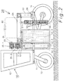
- Fig. 1 as a view from the rear and Fig. 2 as a longitudinal section show an attachment 20 for a grape harvester 10, which comprises all components for treating plants 1 growing in parallel rows in viticulture.
- the harvester 10 has a chassis 11, a cabin 12 for the vehicle driver and a long-leg chassis adapted to the intended use with a steerable front wheel 13 and a driven rear wheel 14.
- the attachment 20 consists essentially of a frame 21 with, for example, four stable feet 22, which are detachably connected in a suitable manner to the chassis 11 of the harvester 10. Eyelets 29 on the feet 22 allow the attachment of stilts. After assembling these stilts, the harvester 10 can move out under the attachment 20 under its own power after lowering its undercarriage or retract under the attachment 20 for the purpose of assembling the attachment 20.
- bracket 23 On the front of the frame 21 there is a bracket 23 on which two cross members 25.1, 25.2 are mounted one above the other transversely to the direction of travel, with the aid of axes 24, so that the cross members 25.1, 25.2 can be pivoted transversely to the direction of travel.
- the corresponding swivel cylinders are not shown for the sake of clarity.
- the crossbeams 25.1, 25.2 can be telescoped twice to the right and to the left.
- An outer recycling screen 40.2, 40.4 is attached to the second telescopic pull-outs 27.1 ... 27.4.
- An inner screen 40.1, 40.3 and an inner blower 50.1, 50.3 hang on the right and left under the frame 21 of the attachment 20.
- a screen 40.1, 40.3 and a blower 50.1, 50.3 face each other. In this way it is prevented that the air flows generated by the inner blowers 50.1, 50.3 meet and interfere with each other.
- the suspensions 41 of the outer screens 40.2, 40.4 and the suspensions 51 of the outer fans 50.2, 50.4 are articulated to the two cross members 25, 26, 27 to form a parallelogram guide.
- This makes it possible to pivot the crossbeams 25, 26, 27 and all components located thereon with respect to the frame 21 and thus with respect to the chassis 11 of the harvester 10. This is necessary when driving on a slope in order to prevent the screens or blowers arranged on the mountain side from sitting on the ground.
- the blowers 50.1 ... 50.4 are each equipped with a number of atomizing nozzles 52. As shown in the drawing, these can be positioned directly in the center of the blower 40. However, it is also possible to position the atomizing nozzles 52 ′ to the side next to the blowers 40, the liquid being injected into the air stream at an acute angle.
- the atomized treatment liquid is directed by the strong air flow generated in the blowers 50.1 ... 50.4 onto the rows of plants 1, which are located between the blower and the screen.
- the part of liquid which does not deposit on the plants 1 and which is very high, for example during the spring spraying, is collected by the screens 40.1 ... 40.4, separated, collected and sucked back into the storage tank 60.
- Hydraulic cylinders are provided for actuating the telescopic extensions 26, 27, which are actuated by the vehicle driver. In order not to disturb the clarity of the drawing, only the hydraulic cylinders 28.1 ... 28.4 for actuating the outer telescopic extensions 27.1 ... 27.4 are shown.
- Fig. 3 shows purely schematically a part of the pipes for the treatment liquid.
- a three-way valve 62 is installed in the pipeline 63 behind the tank 60.
- a pipe socket 64 branches off from this. In conjunction with the three-way valve 62, this pipe socket 64 enables not only the emptying of the tank 60, but in particular the filling thereof, with the aid of the on-board pump 61. It is therefore no longer necessary for the driver of the vehicle to do so Filled tank 60 through the top cap, which, given the height at which the cap is located, makes work considerably easier.
- FIGS. 4 and 5 show a mobile pedestal 10 'with a saddle-mounted attachment 20', which also contains all the components which, for the application of treatment liquid to plants 1 growing in parallel rows, while at the same time recycling the liquid not deposited on the plant rows, all of them Components are shown in the working position.
- the attachment 20 'again consists of a stable frame 21 with, for example, four feet 22 which are connected to the chassis 11 in a non-positive, frictional or positive manner.
- the feet 22 are equipped with locks, bayonet locks, flanges, screw connections or the like.
- Large tanks 60.1, 60.2 for the treatment liquid, a smaller fresh water tank 60.3 and a pump (not shown) sit on the frame 21.
- a traverse 25 with two telescopic arms 25.1, 25.2 arranged one above the other is pivotably mounted on the frame 21 behind the rear of the vehicle 10 by means of a pivot plate 23 and pivot axes 24.
- swivel devices 30.1, 30.2 are mounted, on which outer swivel arms 29.1 ... 29.4 are articulated.
- Telescopic cylinders are provided for telescoping the telescopic arms 25, 26, and 29 hydraulic swivel motors are provided for swiveling the cross member 25, 26 and the swivel arms. However, these are not shown in order to maintain the clarity of the drawing.
- a recycling screen 40.2, 40.4 each hangs by means of suitable brackets 41, the blower and recycling screen being positioned relative to one another in such a way that the air flow, taking into account the driving speed and that caused by the plants Distractions hit the recycling screen at the correct aerodynamic angle.
- the nozzles 52, 52 ′ can not only be mounted directly in front of the blowers 50, but also laterally next to them.
- nozzles 52 '' can be mounted on the side of the outer screens 40.2, 40.4 will; this also sprays the back of the outer rows of plants 1.
- the outer blowers 50.2, 50.4 and recycling screens 40.2, 40.4 are extended or swiveled out according to the spacing of the rows of plants during operation, FIG. 5 showing that the outer recycling screens 40.2, 40.4 are behind the rear of the vehicle 10 'are pivoted.
- FIG. 6 shows that it is possible for road transport to pull the outer blowers 50.2, 50.4 onto the chassis 11 and simultaneously pivot the outer recycling screens 40.2, 40.4 in front of the rear axle, as a result of which dimensions and driving characteristics that are acceptable for road transport can be achieved.
- the reflector screen 70 consists of a rectangular piece of sheet metal, which is aerodynamically curved.
- the air flow 72 loaded with treatment liquid hits the reflector screen 70 at the aerodynamically correct angle, a portion of the liquid separates from the screen 70 and can be drawn off from a collecting channel 71.
- the air flow 72 with the remaining liquid contained therein is deflected to the rear of the row of plants, so that this is also treated, albeit with a reduced amount.
- the device according to the invention as an attachment 20, 20 ', it can be used with any mobile pedestals 10, 10', irrespective of whether these are pulled as self-propelled as in the exemplary embodiments or as described in the prior art.
- the construction is simple and reliable, and so flexible that all types of blowers and recycling screens can be used.
Landscapes
- Life Sciences & Earth Sciences (AREA)
- Engineering & Computer Science (AREA)
- Insects & Arthropods (AREA)
- Pest Control & Pesticides (AREA)
- Wood Science & Technology (AREA)
- Zoology (AREA)
- Environmental Sciences (AREA)
- Harvesting Machines For Specific Crops (AREA)
Abstract
Description
Die Erfindung betrifft Vorrichtungen zum Ausbringen von Behandlungsflüssigkeit auf in parallelen Reihen wachsende Pflanzen, insbesondere im Weinbau, im Obstbau, im Hopfenbau, in der Forstwirtschaft sowie im Tomaten- und/oder Gemüseanbau gemäß dem Oberbegriff des Anspruchs 1.The invention relates to devices for applying treatment liquid to plants growing in parallel rows, in particular in viticulture, in fruit growing, in hop growing, in forestry as well as in tomato and / or vegetable cultivation according to the preamble of
Aus der EP-A-0 327 037, der EP-C-0 382 885, der DE-U-89 06 405 bzw. der DE-U-92 07 095 sind fahrbare Spritzgeräte bekannt, welche speziell zum Behandeln von parallelen Pflanzenreihen im Wein- oder Obstbau geeignet sind. Ihnen gemeinsam sind ein oder mehrere Gebläse, die einen starken, auf die Pflanzenreihen gerichteten Luftstrom erzeugen, Düsen, die eine Behandlungsflüssigkeit in den Luftstrom einspritzen, sowie ein die Pflanzenreihen übergreifendes Gestänge, an dem Recycling-Schirme hängen, die einen mehr oder weniger großen Anteil der Behandlungsflüssigkeit, die sich nicht auf den Pflanzenreihen niedergeschlagen hat, aus der Luftströmung abscheiden, so daß sie aus einer Flüssigkeitssammelrinne am unteren Ende der Recycling-Schirme in den auf dem Fahrzeug mitgeführten Tank zurückgefördert werden kann.From EP-A-0 327 037, EP-C-0 382 885, DE-U-89 06 405 and DE-U-92 07 095, mobile spraying devices are known which are especially suitable for treating parallel rows of plants in the Wine or fruit growing are suitable. What they have in common are one or more blowers that generate a strong airflow directed towards the rows of plants, nozzles that inject a treatment liquid into the airflow, and a linkage spanning the rows of plants, to which recycling umbrellas hang, to a greater or lesser extent separate the treatment liquid, which has not deposited on the rows of plants, from the air flow so that it can be conveyed back from a liquid collecting channel at the lower end of the recycling screens into the tank carried on the vehicle.
Bei den Recycling-Schirmen unterscheidet man zwei Konstruktionen: die Reflektor-Schirme und die Kollektor-Schirme. Die Reflektor-Schirme bestehen im wesentlichen aus aerodynamisch gekrümmten Blechen, die die mit Flüssigkeit beladene Luftströmung gezielt auf die Rückseite der Pflanzenreihen umlenken. Ein erster Anteil der Flüssigkeit scheidet sich dabei am Schirm, ein zweiter Anteil an der Rückseite der Pflanzenreihe ab. Ein Rest der Flüssigkeit ist jedoch verloren und belastet die Umwelt. Außerdem wird die Rückseite der Pflanzenreihe nur mit einer reduzierten Chemikalienmenge behandelt, da der am Schirm abgeschiedene erste Anteil fehlt. Ein weiterer Nachteil ist, daß aufgrund der aerodynamischen Gegebenheiten die Reflektor-Schirme weit hinter dem Fahrzeug positioniert werden müssen, wodurch das Wenden des Fahrzeugs am Ende der Pflanzenreihen sehr erschwert ist.A distinction is made between two designs for the recycling screens: the reflector screens and the collector screens. The reflector umbrellas consist essentially of aerodynamically curved metal sheets, which specifically deflect the air flow loaded with liquid onto the back of the rows of plants. A first part of the liquid separates on the screen, a second part on the back of the row of plants. However, some of the liquid is lost and pollutes the environment. In addition, the back of the row of plants is only treated with a reduced amount of chemicals, since the first part deposited on the screen is missing. Another disadvantage is that due to the aerodynamic conditions, the reflector screens must be positioned far behind the vehicle, which makes it very difficult to turn the vehicle at the end of the rows of plants.
Demgegenüber zeigen die in der EP-C-0 382 885 beschriebenen Kollektor-Schirme erheblich günstigere Eigenschaften. Diese Schirme arbeiten am besten, wenn die flüssigkeitsbeladene Luftströmung praktisch senkrecht auf die Schirmoberfläche trifft. Man erhält so kurze Fahrzeuge, die im Gelände gut zu manipulieren sind. Darüber hinaus ist die Abscheidungsrate bei diesem Schirmtyp praktisch 100 %, so daß nur noch die Anteile der Flüssigkeit, die durch äußere Umstände am Kollektor-Schirm vorbeigelenkt werden, verloren sind. Außerdem wird jede Seite der Pflanzenreihe nacheinander gezielt und gleich dosiert behandelt.In contrast, the collector screens described in EP-C-0 382 885 show considerably more favorable properties. These umbrellas work best when the liquid-laden air flow hits the screen surface practically vertically. This gives you short vehicles that are easy to manipulate off-road. In addition, the deposition rate for this type of screen is practically 100%, so that only the portions of the liquid which are directed past the collector screen by external circumstances are lost. In addition, each side of the row of plants is treated one after the other in a targeted and uniform manner.
Dieses vorbekannte Gerät hat als wesentlichen Vorteil eine maximale Umweltfreundlichkeit bzw. einen minimalen Wasserverbrauch. Allerdings ist das bekannte Gerät nur als Anhänger hinter landwirtschaftlichen Zugfahrzeugen konzipiert.The main advantage of this known device is maximum environmental friendliness and minimal water consumption. However, the known device is only designed as a trailer behind agricultural towing vehicles.
Seit einiger Zeit sind im Weinbau Traubenvollernter im Einsatz. Diese besitzen ein spezielles, sehr hochbeiniges Fahrwerk und können so die Rebzeilen überfahren. Diese Traubenvollernter werden derzeit nur während der Weinlese im Herbst eingesetzt; die restliche Zeit des Jahres stehen sie unbenutzt in der Garage. In anderen Bereichen der Landwirtschaft sieht es ähnlich aus.Grape harvesters have been used in viticulture for some time. These have a special, very long-legged chassis and can thus run over the rows of vines. These grape harvesters are currently only used during the autumn harvest; the rest of the year they are unused in the garage. The situation is similar in other areas of agriculture.
Ausgehend von dem genannten Stand der Technik liegt der vorliegenden Erfindung die Aufgabe zugrunde, Vorrichtungen der eingangs genannten Art zum umweltschonenden Ausbringen von Behandlungsflüssigkeit auf in parallelen Reihen wachsende Pflanzen, insbesondere im Weinbau, aber auch in der Land- und Forstwirtschaft anzugeben, die zur Verwendung mit beliebigen fahrbaren Untersätzen, gleichgültig ob selbstfahrend oder gezogen, geeignet sind.Starting from the prior art mentioned, the present invention is based on the object of providing devices of the type mentioned at the outset for the environmentally friendly application of treatment liquid to plants growing in parallel rows, in particular in viticulture, but also in to indicate to agriculture and forestry that are suitable for use with any mobile pedestals, whether self-propelled or towed.
Diese Aufgabe wird gelöst durch eine gattungsgemäße Vorrichtung mit den Merkmalen gemäß Kennzeichen des Anspruchs 1.This object is achieved by a generic device with the features according to the characterizing part of
Damit ergeben sich die Vorteile, daß sich die fahrbaren Untersätze, bei denen es sich um einen von einer Zugmaschine gezogenen Nachläufer, um den Maschinenkopf eines Traubenvollernters oder um eine Neukonstruktion handeln kann, nicht mehr wie bisher nur selten, beispielsweise nur während der Weinlese, sondern während des ganzen Jahres einsetzen lassen. Dadurch wird ein erster kostensenkender Rationalisierungseffekt erzielt. Weiterhin lassen sich in einem Arbeitsgang drei Pflanzenreihen gleichzeitig behandeln, und zwar je nach der Art, Zahl und Position von Gebläsen und Recycling-Schirmen einseitig und/oder zweiseitig. In allen Fällen erreicht man eine hohe Recyclingrate der Behandlungsflüssigkeit bzw. einen minimalen Wasserverbrauch, was besonders in Ländern mit wenig Wasser von extremer Bedeutung ist. Dank der Teleskopierbarkeit bzw. Schwenkbarkeit der Traversen wird eine akzeptable Straßenfahrbreite sowie eine einfache Anpassung an unterschiedliche Abstände der Pflanzenreihen erreicht.This has the advantages that the mobile pedestals, which can be a trailer pulled by a tractor, the machine head of a grape harvesting machine or a new construction, are no longer only rarely as before, for example only during the harvest, but instead can be used throughout the year. This creates a first cost-reducing rationalization effect. Furthermore, three rows of plants can be treated in one operation, depending on the type, number and position of blowers and recycling screens on one and / or two sides. In all cases, a high recycling rate of the treatment liquid or minimal water consumption is achieved, which is extremely important, especially in countries with little water. Thanks to the telescopic or swiveling of the trusses, an acceptable road width and easy adaptation to different distances between the rows of plants is achieved.
Gemäß einer vorteilhaften Weiterbildung der Erfindung besitzt die Traverse zwei parallele Arme übereinander, die mit den Haltern der äußeren Gebläse und Recycling-Schirme eine Parallelführung bilden. Auf diese Weise ist ein Höhenausgleich möglich, wenn das Gerät am Hang fährt und das Fahrwerk der Hanglage entsprechend verstellt wird. Die Gebläse und Recycling-Schirme hängen jedoch immer senkrecht, d. h. exakt parallel zu den Pflanzenreihen.According to an advantageous development of the invention, the cross member has two parallel arms one above the other, which form a parallel guide with the holders of the outer blowers and recycling screens. In this way, height compensation is possible when the device is driving on a slope and the chassis is adjusted accordingly. However, the blowers and recycling screens always hang vertically, ie exactly parallel to the rows of plants.
Gemäß einer ersten Alternative ist jede Traverse auf jeder Seite zweifach teleskopierbar, wobei an jedem Teleskop-Auszug ein pneumatischer, hydraulischer bzw. elektrischer Antrieb angreift, insbesondere ein Teleskopzylinder.According to a first alternative, each crossbeam can be telescoped twice on each side, a pneumatic, hydraulic or electrical drive acting on each telescopic extension, in particular a telescopic cylinder.
Alternativ dazu ist jede Traverse auf jeder Seite einfach teleskopierbar, wobei an den äußeren Enden der Teleskop-Auszüge Schwenkvorrichtungen vorgesehen sind, an denen Schwenkarme gelagert sind, an deren Enden die äußeren Recycling-Schirme hängen.As an alternative to this, each crossbeam can be simply telescoped on each side, swivel devices being provided on the outer ends of the telescopic pull-outs, on which swivel arms are mounted, at the ends of which the outer recycling screens hang.
Vorzugsweise sind diese äußeren parallelen Schwenkarme sowohl in der horizontalen als auch in der vertikalen Ebene zueinander versetzt. Dadurch bilden sie sowohl ein horizontales als auch ein vertikales Parallelogramm, so daß die Gebläse und die Schirme in jeder beliebigen horizontalen oder vertikalen Schwenkposition der Traversen immer senkrecht hängen.These outer parallel pivot arms are preferably offset from one another both in the horizontal and in the vertical plane. As a result, they form both a horizontal and a vertical parallelogram, so that the fans and the screens always hang vertically in any horizontal or vertical swivel position of the crossbeams.
Zum Ein- und Ausfahren der äußeren Teleskoparme und zum Schwenken der Traverse bzw. der äußeren Schwenkarme können an sich bekannte pneumatische, hydraulische bzw. elektrische Antriebe vorgesehen sein. Hydraulik-Zylinder ermöglichen lange Hubwege; Hydraulik-Schwenkmotoren bauen sehr kompakt und ermöglichen große Schwenkwinkel.Known pneumatic, hydraulic or electrical drives can be provided for extending and retracting the outer telescopic arms and for pivoting the crossmember or the outer pivot arms. Hydraulic cylinders enable long strokes; Hydraulic swivel motors are very compact and allow large swivel angles.
Es versteht sich, daß der Traubenernteaufsatz vor dem Aufsetzen des erfindungsgemäßen Gerätes abgenommen wird. Dies ist bereits werksseitig vorgesehen. Der erfindungsgemäße Aufsatz ist zu demselben Zweck mit Füßen und speziellen Ösen ausgerüstet, an denen Stelzen befestigt werden können, so daß der fahrbare Untersatz mit eigener Kraft montiert bzw. demontiert werden kann.It is understood that the grape harvest attachment is removed before putting on the device according to the invention. This is already provided at the factory. The attachment according to the invention is equipped for the same purpose with feet and special eyelets, on which stilts can be attached, so that the mobile base can be assembled or disassembled under its own power.
Aufgrund der erfindungsgemäßen Konstruktion ist der Aufsatz ohne große Änderungen für praktisch alle fahrbaren Untersätze, gleichgültig ob selbstfahrend oder gezogen geeignet, ebenso zur Verwendung mit allen Recycling-Schirmtypen, gleichgültig ob Reflektor-Schirm oder Kollektor-Schirm.Because of the construction according to the invention, the attachment is suitable for practically all mobile pedestals, regardless of whether it is self-propelled or pulled, without major changes, and also for use with all types of recycling umbrellas, regardless of whether reflector screen or collector screen.
Diese und weitere Ausgestaltungen der Erfindung sind Gegenstand der Unteransprüche. Sie und ihre Vorteile sollen anhand der Zeichnung in Form von Ausführungsbeispielen näher erläutert werden. Es zeigen jeweils in schematischer Darstellung:
- Fig. 1
- eine Ansicht eines ersten Aufsatzes von der Rückseite,
- Fig. 2
- einen Längsschnitt durch einen Vollernter mit dem Aufsatz nach Fig. 1,
- Fig. 3
- einen Teil der Installation für die Behandlungsflüssigkeit,
- Fig. 4
- einen Blick auf das Heck eines Traubenvollernters mit einem anderen Aufsatz zum Ausbringen von Chemikalien auf in parallelen Reihen wachsende Pflanzen in Arbeitsstellung,
- Fig. 5
- eine Seitenansicht des Geräts der Fig. 4 in Arbeitsstellung,
- Fig. 6
- eine Seitenansicht des Geräts der Fig. 4 in Transportstellung,
- Fig. 7
- eine Ansicht eines Reflektor-Schirms als Beispiel eines Recycling-Schirms und
- Fig. 8
- eine Draufsicht auf den Schirm der Fig. 7.
- Fig. 1
- a view of a first essay from the back,
- Fig. 2
- 2 shows a longitudinal section through a harvesting machine with the attachment according to FIG. 1,
- Fig. 3
- part of the installation for the treatment liquid,
- Fig. 4
- a view of the rear of a grape harvesting machine with another attachment for spreading chemicals on plants growing in parallel rows in the working position,
- Fig. 5
- 3 shows a side view of the device of FIG. 4 in the working position,
- Fig. 6
- 3 shows a side view of the device of FIG. 4 in the transport position,
- Fig. 7
- a view of a reflector screen as an example of a recycling screen and
- Fig. 8
- 7 shows a plan view of the screen of FIG. 7.
Fig. 1 als Ansicht von der Rückseite und Fig. 2 als Längsschnitt zeigen einen Aufsatz 20 für einen Traubenvollernter 10, der alle Bestandteile zum Behandeln von in parallelen Reihen wachsenden Pflanzen 1 im Weinbau umfaßt.Fig. 1 as a view from the rear and Fig. 2 as a longitudinal section show an
Der Vollernter 10 besitzt ein Chassis 11, eine Kabine 12 für den Fahrzeugführer sowie ein dem Einsatzzweck angepaßtes hochbeiniges Fahrwerk mit einem lenkbaren Vorderrad 13 und einem angetriebenen Hinterrad 14.The
Der Aufsatz 20 besteht im wesentlichen aus einem Rahmen 21 mit beispielsweise vier stabilen Füßen 22, die in geeigneter Weise lösbar mit dem Chassis 11 des Vollernters 10 verbunden werden. Ösen 29 an den Füßen 22 erlauben die Befestigung von Stelzen. Nach Montage dieser Stelzen kann der Vollernter 10 nach Absenken seines Fahrwerks aus eigener Kraft unter dem Aufsatz 20 herausfahren bzw. zwecks Montage des Aufsatzes 20 wieder unter den Aufsatz 20 hineinfahren.The
An der Frontseite des Rahmens 21 befindet sich eine Konsole 23, an der übereinander quer zur Fahrtrichtung zwei Traversen 25.1, 25.2 montiert sind, und zwar mit Hilfe von Achsen 24, so daß die Traversen 25.1, 25.2 quer zur Fahrtrichtung schwenkbar sind. Die entsprechenden Schwenkzylinder sind der Übersichtlichkeit halber nicht eingezeichnet.On the front of the
Die Traversen 25.1, 25.2 sind nach rechts und nach links zweifach teleskopierbar. An den ersten Teleskopauszügen 26.1 ... 26.4 hängt rechts und links je ein äußeres Gebläse 50.2, 50.4, im vorliegenden Ausführungsbeispiel ein Tangentialgebläse. An den zweiten Teleskopauszügen 27.1 ... 27.4 hängt je ein äußerer Recycling-Schirm 40.2, 40.4.The crossbeams 25.1, 25.2 can be telescoped twice to the right and to the left. An outer blower 50.2, 50.4, in the present exemplary embodiment a tangential blower, hangs on the right and left of the first telescopic extensions 26.1 ... 26.4. An outer recycling screen 40.2, 40.4 is attached to the second telescopic pull-outs 27.1 ... 27.4.
Unter dem Rahmen 21 des Aufsatzes 20 hängen rechts und links jeweils ein innerer Schirm 40.1, 40.3 und ein inneres Gebläse 50.1, 50.3. Jeweils ein Schirm 40.1, 40.3 und ein Gebläse 50.1, 50.3 stehen einander gegenüber. Auf diese Weise wird verhindert, daß die von den inneren Gebläsen 50.1, 50.3 erzeugten Luftströmungen sich treffen und gegenseitig stören.An inner screen 40.1, 40.3 and an inner blower 50.1, 50.3 hang on the right and left under the
Wie insbesondere Fig. 1 erkennen läßt, sind die Aufhängungen 41 der äußeren Schirme 40.2, 40.4 sowie die Aufhängungen 51 der äußeren Gebläse 50.2, 50.4 mit den beiden Traversen 25, 26, 27 unter Bildung einer Parallelogrammführung gelenkig verbunden. Dadurch besteht die Möglichkeit, die Traversen 25, 26, 27 und alle daran sich befindenden Bestandteile gegenüber dem Rahmen 21 und damit gegenüber dem Chassis 11 des Vollernters 10 zu verschwenken. Dies ist bei einer Fahrt am Hang erforderlich, um zu verhindern, daß die bergseitig angeordneten Schirme bzw. Gebläse auf dem Boden aufsitzen.As can be seen in particular in FIG. 1, the
Die Gebläse 50.1 ... 50.4 sind jeweils mit einer Anzahl von Zerstäuberdüsen 52 ausgerüstet. Diese können wie in der Zeichnung dargestellt direkt im Zentrum der Gebläse 40 positioniert sein. Es ist jedoch auch eine Positionierung der Zerstäuberdüsen 52' seitlich neben den Gebläsen 40 möglich, wobei die Flüssigkeit unter spitzem Winkel in den Luftstrom eingespritzt wird. Die zerstäubte Behandlungsflüssigkeit wird von der in den Gebläsen 50.1 ... 50.4 erzeugten starken Luftströmung auf die Pflanzenreihen 1 gerichtet, die sich jeweils zwischen Gebläse und Schirm befinden. Der Teil an Flüssigkeit, der sich nicht auf den Pflanzen 1 niederschlägt und der beispielsweise bei der Frühjahrsspritzung sehr hoch ist, wird von den Schirmen 40.1 ... 40.4 aufgefangen, abgeschieden, gesammelt und in den Vorratstank 60 zurückgesaugt.The blowers 50.1 ... 50.4 are each equipped with a number of
Zum Betätigen der Teleskopauszüge 26, 27 sind jeweils Hydraulikzylinder vorgesehen, die vom Fahrzeugführer betätigt werden. Um die Übersichtlichkeit der Zeichnung nicht zu stören, sind lediglich die Hydraulikzylinder 28.1 ... 28.4 zum Betätigen der äußeren Teleskopauszüge 27.1 ... 27.4 dargestellt.Hydraulic cylinders are provided for actuating the telescopic extensions 26, 27, which are actuated by the vehicle driver. In order not to disturb the clarity of the drawing, only the hydraulic cylinders 28.1 ... 28.4 for actuating the outer telescopic extensions 27.1 ... 27.4 are shown.
Zwecks Erhöhung der Übersichtlichkeit sind weder die Hydraulikleitungen noch die Pumpe oder die Leitungen zum Zuführen der Behandlungsflüssigkeit zu den Spritzdüsen 52 oder die Rücksaugleitungen von den Schirmen 40 zum Tank 60 eingezeichnet.For the sake of clarity, neither the hydraulic lines nor the pump or the lines for supplying the treatment liquid to the
Fig. 3 zeigt rein schematisch einen Teil der Rohrleitungen für die Behandlungsflüssigkeit. Man erkennt den Vorratstank 60 sowie eine Pumpe 61, die über eine im Ring geführte Rohrleitung 63 miteinander verbunden sind. Die hinter der Pumpe 61 vorzusehende Abzweigung zu den Zerstäuberdüsen 52 ist nicht dargestellt. In die Rohrleitung 63 hinter dem Tank 60 ist ein Drei-Wege-Ventil 62 eingebaut. Von diesem zweigt ein Rohrstutzen 64 ab. Dieser Rohrstutzen 64 ermöglicht in Verbindung mit dem Drei-Wege-Ventil 62 nicht nur das Entleeren des Tanks 60, sondern insbesondere das Füllen desselben, und zwar mit Hilfe der bordeigenen Pumpe 61. Es ist also nicht mehr wie bisher erforderlich, daß der Fahrzeugführer den Tank 60 durch den obenliegenden Verschlußdeckel befüllt, was angesichts der Höhe, in der sich der Deckel befindet, eine erhebliche Arbeitserleichterung mit sich bringt.Fig. 3 shows purely schematically a part of the pipes for the treatment liquid. One recognizes the
Die Fig. 4 und 5 zeigen einen fahrbaren Untersatz 10' mit aufgesatteltem Aufsatz 20', der ebenfalls alle Komponenten enthält, die zum Ausbringen von Behandlungsflüssigkeit auf in parallelen Reihen wachsende Pflanzen 1 bei gleichzeitigem Recycling der nicht auf den Pflanzenreihen niedergeschlagenen Flüssigkeit enthält, wobei alle Komponenten in Arbeitsstellung dargestellt sind.4 and 5 show a mobile pedestal 10 'with a saddle-mounted attachment 20', which also contains all the components which, for the application of treatment liquid to
Der Aufsatz 20' besteht wieder aus einem stabilen Rahmen 21 mit beispielsweise vier Füßen 22, die kraft-, reib- oder formschlüssig mit dem Chassis 11 verbunden werden. Die Füße 22 sind zu diesem Zweck mit Verriegelungen, Bajonett-Verschlüssen, Flanschen, Schraubverbindungen oder dergleichen ausgerüstet. Auf dem Rahmen 21 sitzen große Tanks 60.1, 60.2 für die Behandlungsflüssigkeit, ein kleinerer Frischwassertank 60.3 sowie eine Pumpe (nicht dargestellt).The attachment 20 'again consists of a
Des weiteren ist am Rahmen 21 hinter dem Heck des Fahrzeugs 10 eine Traverse 25 mit zwei übereinander angeordneten Teleskoparmen 25.1, 25.2 mittels Schwenkplatte 23 und Schwenkachsen 24 schwenkbar gelagert. An den Enden der Teleskop-Auszüge 26.1 ... 26.4 sind Schwenkvorrichtungen 30.1, 30.2 gelagert, an denen äußere Schwenkarme 29.1 ... 29.4 angelenkt sind. Zum Teleskopieren der Teleskoparme 25, 26 sind Teleskopzylinder, zum Schwenken der Traverse 25, 26 und der Schwenkarme 29 Hydraulik-Schwenkmotoren vorgesehen. Diese sind jedoch nicht dargestellt, um die Übersichtlichkeit der Zeichnung zu erhalten.Furthermore, a traverse 25 with two telescopic arms 25.1, 25.2 arranged one above the other is pivotably mounted on the
An den äußeren Enden der Schwenkarme 29.1 ... 29.4 hängt mittels geeigneter Halterungen 41 je ein Recycling-Schirm 40.2, 40.4, wobei Gebläse und Recycling-Schirm jeweils so zueinander positioniert sind, daß die Luftströmung unter Berücksichtigung der Fahrgeschwindigkeit und der durch die Pflanzen bewirkten Ablenkungen im aerodynamisch richtigen Winkel auf den Recycling-Schirm trifft.On the outer ends of the swivel arms 29.1 ... 29.4, a recycling screen 40.2, 40.4 each hangs by means of
Wie dieses Ausführungsbeispiel zeigt, können die Düsen 52, 52' nicht nur direkt vor den Gebläsen 50 montiert werden, sondern auch seitlich daneben. Außerdem können Düsen 52'' seitlich vorn an den äußeren Schirmen 40.2, 40.4 montiert werden; dadurch wird auch die Rückseite der äußeren Pflanzenreihen 1 besprüht.As this exemplary embodiment shows, the
Wie Fig. 4 zeigt, sind während des Betriebs die äußeren Gebläse 50.2, 50.4 und Recycling-Schirme 40.2, 40.4 entsprechend der Abstände der Pflanzenreihen ausgefahren bzw. ausgeschwenkt, wobei Fig. 5 erkennen läßt, daß die äußeren Recycling-Schirme 40.2, 40.4 hinter das Heck des Fahrzeugs 10' geschwenkt sind. Wie Fig. 6 erkennen läßt, ist es jedoch für den Straßentransport möglich, die äußeren Gebläse 50.2, 50.4 an das Chassis 11 beizuziehen und die äußeren Recycling-Schirme 40.2, 40.4 gleichzeitig vor die Hinterachse zu schwenken, wodurch für den Straßentransport akzeptable Abmessungen und Fahreigenschaften erreicht werden.As shown in FIG. 4, the outer blowers 50.2, 50.4 and recycling screens 40.2, 40.4 are extended or swiveled out according to the spacing of the rows of plants during operation, FIG. 5 showing that the outer recycling screens 40.2, 40.4 are behind the rear of the vehicle 10 'are pivoted. As can be seen in FIG. 6, however, it is possible for road transport to pull the outer blowers 50.2, 50.4 onto the
Schließlich besteht sogar die Möglichkeit, die äußeren Schirme 40.2, 40.4 und Gebläse 50.2, 50.4 oben auf das Deck des Fahrzeugs 10, 10' zu legen, wie Flügel von Insekten.Finally, there is even the possibility of placing the outer screens 40.2, 40.4 and blowers 50.2, 50.4 on top of the deck of the
Da die Kollektor-Schirme aus parallelen Lamellen mit W-förmigem Querschnitt in der eingangs erwähnten EP-C-0 382 885 ausführlich beschrieben sind, erübrigt sich hier eine ausführliche Beschreibung von Aufbau und Wirkungsweise. Stattdessen soll anhand der Fig. 7 und 8 ein Reflektor-Schirm erläutert werden. Der Reflektor-Schirm 70 besteht aus einem rechteckigen Blechstück, welches aerodynamisch gebogen ist. Wenn die mit Behandlungsflüssigkeit beladene Luftströmung 72 unter dem aerodynamisch richtigen Winkel auf den Reflektor-Schirm 70 trifft, scheidet sich ein Anteil der Flüssigkeit am Schirm 70 ab und kann aus einer Sammelrinne 71 abgezogen werden. Die Luftströmung 72 mit dem darin enthaltenen Rest an Flüssigkeit wird umgelenkt auf die Rückseite der Pflanzenreihe, so daß auch diese mit behandelt wird, wenn auch mit einer reduzierten Menge.Since the collector screens made of parallel lamellas with a W-shaped cross section are described in detail in EP-C-0 382 885 mentioned at the outset, a detailed description of the structure and mode of operation is unnecessary here. Instead, a reflector screen will be explained with reference to FIGS. 7 and 8. The
Dank der Konzeption der erfindungsgemäßen Vorrichtung als Aufsatz 20, 20' läßt sie sich mit beliebigen fahrbaren Untersätzen 10, 10' verwenden, gleichgültig ob diese wie in den Ausführungsbeispielen selbstfahrend oder wie im Stand der Technik beschrieben gezogen sind. Darüber hinaus ist die Konstruktion einfach und betriebssicher sowie derart flexibel, daß alle Arten von Gebläsen und Recycling-Schirmen verwendet werden können.Thanks to the design of the device according to the invention as an
Claims (13)
Applications Claiming Priority (4)
| Application Number | Priority Date | Filing Date | Title |
|---|---|---|---|
| DE9207095U | 1992-05-26 | ||
| DE9207095U DE9207095U1 (en) | 1992-05-26 | 1992-05-26 | Device for applying chemicals to rows of plants |
| DE9301379U | 1993-02-02 | ||
| DE9301379U DE9301379U1 (en) | 1993-02-02 | 1993-02-02 | Device for applying chemicals to rows of plants |
Publications (1)
| Publication Number | Publication Date |
|---|---|
| EP0574740A1 true EP0574740A1 (en) | 1993-12-22 |
Family
ID=25959537
Family Applications (1)
| Application Number | Title | Priority Date | Filing Date |
|---|---|---|---|
| EP93108409A Withdrawn EP0574740A1 (en) | 1992-05-26 | 1993-05-25 | Apparatus for the spraying of treating liquid on rows of plants |
Country Status (2)
| Country | Link |
|---|---|
| EP (1) | EP0574740A1 (en) |
| AU (1) | AU3878193A (en) |
Cited By (16)
| Publication number | Priority date | Publication date | Assignee | Title |
|---|---|---|---|---|
| FR2762187A1 (en) * | 1997-04-21 | 1998-10-23 | Muizon Motoculture | Sprayer for treating plants grown in lines |
| WO1999013713A1 (en) * | 1997-09-16 | 1999-03-25 | Land Restore Uk Limited | Liquid and or chemical application apparatus |
| FR2855719A1 (en) * | 2003-06-06 | 2004-12-10 | Multeyme S L | Angular vertical flow nebulizer for applying phyto-sanitary product, has vertical distributors with support structures connected to central support structure of another support structure that permits to adjust width of work |
| FR2921543A1 (en) * | 2007-10-02 | 2009-04-03 | Pierre Corpel | Phytosanitary product spraying device for e.g. vineyard, has slider block slid on spray boom to take two extreme positions such that cylinder of one arm presents higher displacement course than course of cylinder of another arm |
| FR2925861A1 (en) * | 2007-12-28 | 2009-07-03 | Pulvexper Sarl | Treatment product spraying device for e.g. viticulture, has vertical elements of support structure comprising nozzles for spraying treatment product, where nozzles are associated to fans pointed horizontally in direction of one of elements |
| NL1039524C2 (en) * | 2012-04-06 | 2013-10-09 | H Hol & Zoon V O F | SELF-RIDING PORTAL VEHICLE. |
| CN103521380A (en) * | 2013-10-17 | 2014-01-22 | 山东农业大学 | Pneumatic conveying type suspender profiling ripener spraying machine for cotton fields |
| FR3010862A1 (en) * | 2013-09-20 | 2015-03-27 | Rothschild Philippe | VARIABLE SPLITTING SPRAY DEVICE |
| IT201700088723A1 (en) * | 2017-08-01 | 2019-02-01 | Dragone S R L | NEBULIZING MACHINE FOR PESTICIDIAL TREATMENT OF PLANTS ORGANIZED IN ROOFS |
| WO2019102169A1 (en) * | 2017-11-27 | 2019-05-31 | Exel Industries | Collection panel |
| CN110463679A (en) * | 2019-09-09 | 2019-11-19 | 南京农业大学 | A kind of orchard gate solid air-assisted type spraying machine |
| IT201800009422A1 (en) * | 2018-10-12 | 2020-04-12 | Ocllsrl | Multi-purpose atomizer. |
| WO2020221972A1 (en) * | 2019-04-30 | 2020-11-05 | Exel Industries | Modular spray system |
| CN112772615A (en) * | 2021-01-06 | 2021-05-11 | 莱芜职业技术学院 | A automatic all-round medicine device that spouts for grape is planted |
| FR3118852A1 (en) * | 2021-01-20 | 2022-07-22 | olivier moulinet | Row Crop Horizontal Progress Vertical Arch Sprayer |
| WO2022195380A1 (en) * | 2021-03-18 | 2022-09-22 | Ecorobotix Sa | Spot spraying method and system for high precision application of agrochemicals |
Families Citing this family (2)
| Publication number | Priority date | Publication date | Assignee | Title |
|---|---|---|---|---|
| CN102613160B (en) * | 2012-03-22 | 2014-04-09 | 北京农业信息技术研究中心 | Self-walking variable-quantity liquid medicine spraying device and liquid medicine spraying method for grapery |
| CN109077045B (en) * | 2018-09-17 | 2023-08-29 | 极目(海南)智能育种装备有限公司 | Spraying device with liquid drop recycling function |
Citations (4)
| Publication number | Priority date | Publication date | Assignee | Title |
|---|---|---|---|---|
| FR2416737A1 (en) * | 1978-02-08 | 1979-09-07 | Loiseau Ets | Agricultural crop spraying machine - has nozzle heads at spray pipe ends creating air currents towards plants |
| EP0327037A2 (en) * | 1988-02-03 | 1989-08-09 | NEUMO Grundbesitz-GmbH | Plant protection sprayer |
| EP0382885A1 (en) * | 1989-05-24 | 1990-08-22 | Walter, Helga | Movable sprayer for chemical treatment of plants growing in parallel rows |
| DE3914117A1 (en) * | 1989-04-28 | 1990-10-31 | Helge Ebeling | Pesticide spray system for plants - has two independently movable halves with opposing inlet and outlet to avoid environment contamination |
-
1993
- 1993-05-25 AU AU38781/93A patent/AU3878193A/en not_active Abandoned
- 1993-05-25 EP EP93108409A patent/EP0574740A1/en not_active Withdrawn
Patent Citations (4)
| Publication number | Priority date | Publication date | Assignee | Title |
|---|---|---|---|---|
| FR2416737A1 (en) * | 1978-02-08 | 1979-09-07 | Loiseau Ets | Agricultural crop spraying machine - has nozzle heads at spray pipe ends creating air currents towards plants |
| EP0327037A2 (en) * | 1988-02-03 | 1989-08-09 | NEUMO Grundbesitz-GmbH | Plant protection sprayer |
| DE3914117A1 (en) * | 1989-04-28 | 1990-10-31 | Helge Ebeling | Pesticide spray system for plants - has two independently movable halves with opposing inlet and outlet to avoid environment contamination |
| EP0382885A1 (en) * | 1989-05-24 | 1990-08-22 | Walter, Helga | Movable sprayer for chemical treatment of plants growing in parallel rows |
Cited By (24)
| Publication number | Priority date | Publication date | Assignee | Title |
|---|---|---|---|---|
| FR2762187A1 (en) * | 1997-04-21 | 1998-10-23 | Muizon Motoculture | Sprayer for treating plants grown in lines |
| WO1999013713A1 (en) * | 1997-09-16 | 1999-03-25 | Land Restore Uk Limited | Liquid and or chemical application apparatus |
| GB2334687A (en) * | 1997-09-16 | 1999-09-01 | Land Restore Uk Ltd | Liquid and or chemical application apparatus |
| FR2855719A1 (en) * | 2003-06-06 | 2004-12-10 | Multeyme S L | Angular vertical flow nebulizer for applying phyto-sanitary product, has vertical distributors with support structures connected to central support structure of another support structure that permits to adjust width of work |
| ES2249087A1 (en) * | 2003-06-06 | 2006-03-16 | Multeyme, S.L. | Angular vertical flow nebulizer for applying phyto-sanitary product, has vertical distributors with support structures connected to central support structure of another support structure that permits to adjust width of work |
| FR2921543A1 (en) * | 2007-10-02 | 2009-04-03 | Pierre Corpel | Phytosanitary product spraying device for e.g. vineyard, has slider block slid on spray boom to take two extreme positions such that cylinder of one arm presents higher displacement course than course of cylinder of another arm |
| FR2925861A1 (en) * | 2007-12-28 | 2009-07-03 | Pulvexper Sarl | Treatment product spraying device for e.g. viticulture, has vertical elements of support structure comprising nozzles for spraying treatment product, where nozzles are associated to fans pointed horizontally in direction of one of elements |
| NL1039524C2 (en) * | 2012-04-06 | 2013-10-09 | H Hol & Zoon V O F | SELF-RIDING PORTAL VEHICLE. |
| FR3010862A1 (en) * | 2013-09-20 | 2015-03-27 | Rothschild Philippe | VARIABLE SPLITTING SPRAY DEVICE |
| CN103521380A (en) * | 2013-10-17 | 2014-01-22 | 山东农业大学 | Pneumatic conveying type suspender profiling ripener spraying machine for cotton fields |
| CN103521380B (en) * | 2013-10-17 | 2015-10-07 | 山东农业大学 | Cotton field wind spraying aid type suspension rod profiling ripener spraying machine |
| IT201700088723A1 (en) * | 2017-08-01 | 2019-02-01 | Dragone S R L | NEBULIZING MACHINE FOR PESTICIDIAL TREATMENT OF PLANTS ORGANIZED IN ROOFS |
| WO2019102169A1 (en) * | 2017-11-27 | 2019-05-31 | Exel Industries | Collection panel |
| FR3074015A1 (en) * | 2017-11-27 | 2019-05-31 | Exel Industries | PULVERIZED LIQUID RECOVERY PANEL, SUPPORTING DEVICE, AND EQUIPPED AGRICULTURAL SPRAYER |
| CN111565567A (en) * | 2017-11-27 | 2020-08-21 | 艾格赛尔工业公司 | Collection panel |
| IT201800009422A1 (en) * | 2018-10-12 | 2020-04-12 | Ocllsrl | Multi-purpose atomizer. |
| WO2020221972A1 (en) * | 2019-04-30 | 2020-11-05 | Exel Industries | Modular spray system |
| FR3095573A1 (en) * | 2019-04-30 | 2020-11-06 | Exel Industries | MODULAR SPRAYING SYSTEM |
| CN110463679A (en) * | 2019-09-09 | 2019-11-19 | 南京农业大学 | A kind of orchard gate solid air-assisted type spraying machine |
| CN112772615A (en) * | 2021-01-06 | 2021-05-11 | 莱芜职业技术学院 | A automatic all-round medicine device that spouts for grape is planted |
| CN112772615B (en) * | 2021-01-06 | 2022-07-12 | 莱芜职业技术学院 | A automatic all-round medicine device that spouts for grape is planted |
| FR3118852A1 (en) * | 2021-01-20 | 2022-07-22 | olivier moulinet | Row Crop Horizontal Progress Vertical Arch Sprayer |
| WO2022157121A1 (en) * | 2021-01-20 | 2022-07-28 | Moulinet Olivier | Vertical arch sprayer with horizontal progression for cultivation in rows |
| WO2022195380A1 (en) * | 2021-03-18 | 2022-09-22 | Ecorobotix Sa | Spot spraying method and system for high precision application of agrochemicals |
Also Published As
| Publication number | Publication date |
|---|---|
| AU3878193A (en) | 1993-12-02 |
Similar Documents
| Publication | Publication Date | Title |
|---|---|---|
| DE69404865T2 (en) | AGRICULTURAL SPRAYING UNIT AND THEIR AIR GENERATOR | |
| EP0574740A1 (en) | Apparatus for the spraying of treating liquid on rows of plants | |
| DE1949978C3 (en) | Agricultural motor vehicle, in particular tractor | |
| DE3803145A1 (en) | PLANT PROTECTION DISCHARGE DEVICE | |
| DE202011001292U1 (en) | Tunnel washing vehicle | |
| DE3509040C2 (en) | ||
| DE7338262U (en) | AGRICULTURAL MACHINE | |
| DE102007002046B4 (en) | Device for spraying plant lines | |
| EP0382885B1 (en) | Movable sprayer for chemical treatment of plants growing in parallel rows | |
| DE102019007650A1 (en) | Agricultural distributing machine with a boom and method for its manufacture | |
| EP3512334B1 (en) | Atomiser for fruit trees | |
| DE3404760C2 (en) | Mobile sprayer | |
| EP0113335A1 (en) | Motor vehicle with a variable position driver's cab | |
| EP3957148A1 (en) | Device for distributing liquid manure | |
| DE3346309A1 (en) | Motor vehicle with positionally variable driver's cab | |
| DE69200616T2 (en) | Irrigation cannon. | |
| DE9301379U1 (en) | Device for applying chemicals to rows of plants | |
| DE2450386A1 (en) | POWING SYSTEM WITH SEVERAL INDIVIDUAL PLOWS, CONTINUOUSLY ADJUSTABLE DISTANCE | |
| DE9205096U1 (en) | Mobile sprayer | |
| DE4018380C2 (en) | ||
| DE9207095U1 (en) | Device for applying chemicals to rows of plants | |
| DE69711809T2 (en) | Device and method for applying liquid and pesticides to the soil | |
| DE10227959B4 (en) | Tunnel spray for row crops, in particular grapevines | |
| DE69000201T2 (en) | DEVICE FOR APPLYING A TREATMENT TO TREE AND SHRUB. | |
| DE20014438U1 (en) | Device for spreading liquid mixtures for agricultural tillage and plant cultivation |
Legal Events
| Date | Code | Title | Description |
|---|---|---|---|
| PUAI | Public reference made under article 153(3) epc to a published international application that has entered the european phase |
Free format text: ORIGINAL CODE: 0009012 |
|
| AK | Designated contracting states |
Kind code of ref document: A1 Designated state(s): AT BE CH DE DK ES FR GB GR IE IT LI LU MC NL PT SE |
|
| 17P | Request for examination filed |
Effective date: 19931229 |
|
| RBV | Designated contracting states (corrected) |
Designated state(s): CH DE ES FR IT LI PT |
|
| STAA | Information on the status of an ep patent application or granted ep patent |
Free format text: STATUS: THE APPLICATION IS DEEMED TO BE WITHDRAWN |
|
| 18D | Application deemed to be withdrawn |
Effective date: 19960501 |