EP1685755B1 - Self-propelled harvester - Google Patents
Self-propelled harvester Download PDFInfo
- Publication number
- EP1685755B1 EP1685755B1 EP06001485.9A EP06001485A EP1685755B1 EP 1685755 B1 EP1685755 B1 EP 1685755B1 EP 06001485 A EP06001485 A EP 06001485A EP 1685755 B1 EP1685755 B1 EP 1685755B1
- Authority
- EP
- European Patent Office
- Prior art keywords
- harvester
- harvesting device
- self
- parts
- travelling
- Prior art date
- Legal status (The legal status is an assumption and is not a legal conclusion. Google has not performed a legal analysis and makes no representation as to the accuracy of the status listed.)
- Active
Links
Images


Classifications
-
- A—HUMAN NECESSITIES
- A01—AGRICULTURE; FORESTRY; ANIMAL HUSBANDRY; HUNTING; TRAPPING; FISHING
- A01D—HARVESTING; MOWING
- A01D41/00—Combines, i.e. harvesters or mowers combined with threshing devices
- A01D41/12—Details of combines
- A01D41/14—Mowing tables
- A01D41/144—Foldable headers
Definitions
- the invention relates to a self-propelled agricultural harvester according to the preamble of claim 1, which comprises a harvester that, in particular by its design and flexibility significantly increases the efficiency of the harvester.
- Harvesting machines of the aforementioned type are available in numerous embodiments, preferably these are harvesting machines with a harvesting header for harvesting stalk-like crops such as corn or the like. Performance and speed are demands that need to be constantly improved. However, increasing the working widths of the attachments, which are made possible by ever greater engine power of the harvesting machines and thus increase the performance of the harvester, but require more and more complex solutions in terms of handling and transport.
- the Applicant discloses a harvester with a centrally divided harvester in which the two halves can be pivoted from a working position parallel to the ground into a vertical transport position.
- a harvesting device has been created by simple means, which offers a large working width with low weight and design effort, taking into account the aforementioned legal provisions.
- the requirement for even greater working widths however, set a limit in this embodiment by the legally permissible transport height.
- the visual obstruction is reduced by the cleverly arranged in the transport position harvester halves by the clever arrangement of the pivot axes to a minimum, but not completely avoided.
- a harvesting attachment for a combine harvester which consists of a fixedly connected to the combine center part and two pivotally hinged thereto side parts.
- the side parts take a subsequent to the expansion of the central part, aligned approximately parallel to the ground position, from which they can be transferred for transport on the road by a pivoting movement about an axis directed in the direction of travel in a transport position, in the the side parts rest with their top side by side on top of the middle part. It follows that the working width of the side parts can correspond to a maximum of half the working width of the middle part.
- both the side parts and the middle part in series are assigned divider tips with associated conveyors, which allow only a promotion of the crop in a direction of travel in the opposite direction. With this harvester so no directed transversely to the direction of travel, row-independent and a central intake inflowing promotion is reached.
- the invention is therefore an object of the invention to improve a generic self-propelled agricultural harvester such that when transporting with cultivated harvester, which has a working width of at least approximately three times the transport width and is particularly light and simple in construction, while complying with all legal provisions, especially with regard to the transport dimensions, the field of vision of the driver is not restricted by the harvesting device.
- a self-propelled agricultural harvester with a front in the travel and / or working direction arranged in front of a driver's station, at least formed of a central part and side panels and aligned in its longest orientation transversely to the direction of travel and working harvester, which is designed in that, as a result of an approximately 180 degree pivoting movement of at least two side parts of the harvesting device about pivot axes lying in at least approximately in the direction of travel and working direction, these side parts can be transferred from a position transverse to the travel and working direction into a transport position such that they are suitable for road travel the harvester legally permissible dimensions, in particular with respect to transport width are met and the at least two pivotable side parts whose transversely directed to the travel and working direction longitudinal extent in each case at least ann Hernd the maximum allowable transport width, are stored by adhering to a follow-up sequence in the pivoting after pivoting each other on the middle part with its underside upwards, each part of the harvester at least one mowing and /
- the side parts may have a width which corresponds approximately to the width of the middle part and thus the transport width. This means that the total working width is approximately three times the transport width.
- the wide version of the side parts of the harvester of a harvester according to the invention is made possible by the skillful vertically offset arrangement of the pivot axes of the side parts and by observing a follow-up sequence in the pivoting of the side parts after pivoting on top of each other on the middle part with its bottom above are at least approximately parallel to each other.
- the pivot axes of the side parts according to the invention are not exactly parallel to an imaginary vertical center plane of the harvester.
- the side parts pivot such that protruding components of harvesting equipment parts do not collide with other components during pivoting and intervene in the final transport position in existing open spaces.
- a harvesting device thus brought into transport position is so compact in the overall height that the field of vision of the driver of the harvesting machine is not restricted by the harvesting device. This benefits not only the overview and the ride comfort but in particular the traffic safety.
- Another major advantage of the invention lies in the compact dimensions and low weight of the harvesting device. These features significantly improve drivability due to the low center of gravity and a short distance to the front of the harvester, especially at high speeds on the road.
- a harvester with more than three parts which forms a package with four or more layers of harvester sections after pivoting into the transport position using the features according to the invention.
- the inventive design of the harvesting device and in particular by the inventive arrangement of the pivot axes of the side parts it is possible to operate the harvester by pivoting one or both sides of the harvester in a vertical inoperative position with different working widths without changing the harvesting device.
- These different operating positions open up completely new ways of working for the machine operator. It is thus possible, for example, to harvest a region at the beginning of the field only with the middle part of the harvesting device, which then makes it possible to completely unfold the harvesting device in the field without loss of crop. Especially for harvesters with a large working width a complete unfolding outside the field is often not possible, which is why then crop losses had to be taken by driving in and out in the crop in purchasing.
- the working width of the middle harvesting device part is in the inoperative position located side pieces tuned to a standardized row spacing of the crop so that a safe harvest of a number of rows is guaranteed, so the other rows of crops are neither damaged by parts of the harvester nor by the harvester itself or demolished.
- a harvesting machine is provided by the particularly advantageous features of the invention, which comprises a very flexible harvester with an increased working width, which represents no visual impairment of the driver in the transport position and significantly increases the traffic safety during transport.
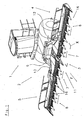
- FIG. 1 An example of a self-propelled agricultural harvester 1 in the embodiment of a forage harvester with a harvester 2, which is used in particular as an attachment for row-independent harvesting of stalk-like crop such as corn or the like, is in Fig. 1 illustrated and preferably consists, as shown here, of three parts 3, 4, 5.
- a fixedly connected via a base frame 6 with the harvester middle part 3 are assigned at the edge of this on each pivot axis 12, 13 hinged side panels 4, 5 ,
- the side parts 4, 5 supported in a manner not described laterally on the middle part 3 and locked if necessary.
- the middle part 3, as well as the side parts 4, 5 each include mowing and conveying means 7, 8, which circumferentially driven the crop with outwardly facing cutting and holding elements 9, 10 separate, record and promote further.
- the drive of the mowing and conveying means 7, 8 takes place in a manner not shown via drive trains from a power source of the connected harvester 1.
- the drive trains of the side parts 4, 5 are separated and vice versa when pivoting the side parts 4, 5 automatically reconnected in their working and operating position.
- the harvesting device 2 is pre-assembled exactly in the middle of the harvester 1, so that it extends symmetrically to a vertical longitudinal center plane of the harvester 1 to both sides.
- the middle part of the harvesting device 2 is equipped with two mowing and conveying means 7, which rotates in the opposite direction in the direction of arrow V the crop of the harvesting machine 1 respectively.
- the side parts 4, 5 of the harvester 2 of the harvesting machine 1 of the embodiment are advantageously each equipped with only one mowing and conveying means 8, which in the direction of arrow V driven circumferentially during the working cycle of the harvester, the entire harvestable crop of him exclusively on his in the direction of travel F. separating front side, absorbs and further promotes.
- the advantages of an embodiment of the side parts 4, 5 with only one mowing and conveying means 8 are the particularly low weight, the very compact size and thus the favorable center of gravity and the drive technology simple design. Especially with ever larger working widths of the harvesting devices are the important criteria that affect the production price, handling and transport options of the harvesting device crucial.
- the very short design of a harvesting device 2 of the example brings already in the Fig. 1 shown working position advantages with respect to short paths of the crop to the catchment area 11 of the harvester 1 and a favorable axle load distribution of the harvester.
- the in the Fig. 2 illustrated transport position of the harvesting device makes even more very advantageous features clear. From a working position of the harvesting device 2 according to Fig.
- the side part 5 is pivoted about the lower pivot axis 13 by 180 degrees, so that it is then placed with the underside facing upward on the middle part 3.
- the oblique orientation of the pivot axis causes the side member 5 as close as possible to the middle part 3 spaced on this can be stored without colliding with other components of the harvester 2.
- the second side part 4 also the pivoting 180 degrees, but to the much higher, but also for the same reasons obliquely arranged pivot axis 12, the high arrangement of the pivot axis 12 causes the side member 4 with its underside facing upward on the already pivoted side part 5 stores in transport position.
- slightly offset orientation of the harvesting equipment parts 3, 4, 5 in the transport position to each other is in Fig. 2 can be seen by the lines a, b and c, which serve as extensions of the front lines of the harvesting equipment parts 3, 4, 5 only for clarity.
- the advantageous transport position of the harvesting device 2 of the harvesting machine according to the invention is on in Fig. 2 illustrated embodiment particularly clear.
- the harvester 2 with a working width of almost three times the harvester width forms such a compact unit in its transport position that it does not adversely affect the driving characteristics when it is left in front of the harvester 1 during the transport journey due to its low weight and the low center of gravity that is close to the harvester Furthermore, it does not restrict the driver's field of vision and thus significantly improves traffic safety.
- the harvesting machine 1 according to the invention can by the advantageous design of his harvester 2 except in the in Fig. 1 and Fig. 2 shown operating modes are still operated in other advantageous modes.
- the mowing and conveying means 7, 8 primarily, as in particular in the detailed view of Fig. 3 recognizable, hingedly interconnected sub-segments 14 with arranged at this outwardly facing cutting and holding elements 9, 10, which lie in superimposed planes E1, E2, E3.
- Each sub-segment 14 has in each case in the lower plane E1 a cutting element 9, in the middle plane E2 each have a holding element 10 and in the upper level E3 also only one further holding element 10.
- the articulated interconnected sub-segments 14 of the mowing and conveying means 7, 8 are driven in rotation around at least two drive and deflection wheels not shown so that they separate the crop with their running in the direction of travel and forward F running, record and in the art an endless conveyor linearly in the direction of arrow V to the center of the harvester 2 promote.
- a critical point of the promotion is the trouble-free and loss-free transfer of the crop at the interfaces between the middle part 3 and side panels 4, 5. In these areas, the entire previously taken up by the mowing and conveying means 8 and promoted crop to the inside Mowing and conveying 7 handed over the respective harvester side and are absorbed by this, while simultaneously separating and picking up further crop.
Description
Die Erfindung bezieht sich auf eine selbstfahrende landwirtschaftliche Erntemaschine nach dem Oberbegriff des Anspruchs 1, welche ein Erntegerät umfasst, dass insbesondere durch seine Gestaltung und Flexibilität die Leistungsfähigkeit der Erntemaschine erheblich steigert. Erntemaschinen der zuvor genannten Art gibt es in zahlreichen Ausführungsformen, vorzugsweise handelt es sich hierbei um Erntemaschinen mit einem Erntevorsatzgerät zur Ernte von stängelartigen Erntegut wie Mais oder dergleichen. Leistungsfähigkeit und Schnelligkeit sind Forderungen, die es immer weiter zu verbessern gilt. Immer größere Arbeitsbreiten der Vorsatzgeräte, die durch immer größere Motorleistungen der Erntemaschinen ermöglicht werden und so die Leistungsfähigkeit der Erntemaschine steigern, erfordern jedoch immer aufwändigere Lösungen bezüglich Handhabung und Transport.The invention relates to a self-propelled agricultural harvester according to the preamble of
Um bei Transportfahrten von Erntemaschinen mit Erntegeräten großer Arbeitsbreite einen besonders zeitaufwändigen Abbau des Erntegerätes und ein Mitführen auf einem gesonderten Transportwagen zu vermeiden, sind bereits verschiedene Ausführungsformen von Erntegeräten bekannt, die in der Transportstellung eine Breitenreduzierung ermöglichen. Um die gesetzlichen Vorschriften für die Straßenfahrt einer Erntemaschine einzuhalten, ist jedoch nicht nur eine maximale Breite von beispielsweise 3 Meter einzuhalten, sondern ebenso eine höchstzulässige Transporthöhe und eine maximal zulässige Einschränkung des Sichtfeldes des Fahrers, sowie eine maximale Achslast.In order to avoid a particularly time-consuming dismantling of the harvesting device and entrainment on a separate trolley when transporting harvesters with harvesters large working width, various embodiments of harvesters are already known that allow a width reduction in the transport position. In order to comply with the legal requirements for road driving a harvester, however, not only a maximum width of, for example, 3 meters is observed, but also a maximum transport height and a maximum allowable restriction of the driver's field of view, and a maximum axle load.
In der
Aus der
Weitere bekannte Lösungen, bei denen die Erntegeräte der Erntemaschinen mehrteilig ausgeführt sind und um mehr als zwei Achsen geklappt und/oder geschwenkt werden, ermöglichen eventuell eine größere Arbeitsbreite, verursachen aber allesamt eine Sichtbehinderung des Fahrers der Erntemaschine. Besonders nachteilig ist bei diesen Lösungen aber auch der hohe konstruktive Aufwand und das damit verbundene hohe Gewicht, die erschwerte Handhabung, die negative Beeinflussung des Erntemaschinenschwerpunktes und nicht zuletzt die hohen Herstellkosten.Other known solutions in which the harvesters of the harvesters are made in several parts and are folded and / or pivoted by more than two axes, possibly allow a larger working width, but all cause a visual obstruction of the driver of the harvester. Especially A disadvantage of these solutions but also the high design complexity and the associated high weight, the difficult handling, the negative impact on the harvester focus and not least the high production costs.
Der Erfindung liegt daher die Aufgabe zugrunde, eine gattungsgemäße selbstfahrende landwirtschaftliche Erntemaschine derart zu verbessern, dass bei Transportfahrten mit angebautem Erntegerät, welches eine Arbeitsbreite von zumindest annähernd der dreifachen Transportbreite hat und dabei besonders leicht und einfach im Aufbau ist, bei Einhaltung aller gesetzlichen Bestimmungen, insbesondere bezüglich der Transportabmessungen das Sichtfeldes des Fahrers nicht durch das Erntegerät eingeschränkt wird.The invention is therefore an object of the invention to improve a generic self-propelled agricultural harvester such that when transporting with cultivated harvester, which has a working width of at least approximately three times the transport width and is particularly light and simple in construction, while complying with all legal provisions, especially with regard to the transport dimensions, the field of vision of the driver is not restricted by the harvesting device.
Erfindungsgemäß wird diese Aufgabe durch die im Patentanspruch 1 genannten Merkmale gelöst.According to the invention this object is achieved by the features mentioned in
Gemäß der Erfindung ergibt sich eine selbstfahrende landwirtschaftliche Erntemaschine mit einem im Frontbereich in Fahrt- und/oder Arbeitsrichtung vor einem Fahrerstand angeordneten, zumindest aus einem Mittelteil und Seitenteilen gebildeten und in seiner längsten Ausrichtung quer zur Fahrt- und Arbeitsrichtung ausgerichteten Erntegerät, welches so gestaltet ist, dass durch eine annähernd 180 Grad Schwenkbewegung von mindestens zwei Seitenteilen des Erntegerätes um in zumindest annähernd in Fahrt- und Arbeitsrichtung liegenden Schwenkachsen diese Seitenteile derart aus einer quer zur Fahrt- und Arbeitsrichtung sich erstreckenden Betriebsstellung in eine Transportstellung überführbar sind, dass die für die Straßenfahrt der Erntemaschine gesetzlich zulässigen Abmessungen, insbesondere bezüglich Transportbreite eingehalten werden und die zumindest zwei schwenkbeweglichen Seitenteile, deren quer zur Fahrt- und Arbeitsrichtung gerichtete Längserstreckung jeweils zumindest annähernd der maximal zulässigen Transportbreite entspricht, durch Einhaltung eines Folgeablaufes bei der Verschwenkung nach dem Verschwenken übereinander auf dem Mittelteil mit ihrer Unterseite jeweils nach oben zeigend abgelegt sind, wobei jedem Teil des Erntegerätes zumindest ein Mäh- und/oder Fördermittel zugeordnet ist und diese als Endlosförderer das Erntegut einem Einzugsbereich der Erntemaschine zuführen, wobei die Mäh- und Fördermittel der Seitenteile während der Arbeitsfahrt der Erntemaschine ein Abtrennen, Aufnehmen und Weiterbefördern des gesamten, erfassbaren Erntegutes an der in Fahrtrichtung weisenden Vorderseite zum Mittelteil hin bewirken.According to the invention, a self-propelled agricultural harvester with a front in the travel and / or working direction arranged in front of a driver's station, at least formed of a central part and side panels and aligned in its longest orientation transversely to the direction of travel and working harvester, which is designed in that, as a result of an approximately 180 degree pivoting movement of at least two side parts of the harvesting device about pivot axes lying in at least approximately in the direction of travel and working direction, these side parts can be transferred from a position transverse to the travel and working direction into a transport position such that they are suitable for road travel the harvester legally permissible dimensions, in particular with respect to transport width are met and the at least two pivotable side parts whose transversely directed to the travel and working direction longitudinal extent in each case at least ann Hernd the maximum allowable transport width, are stored by adhering to a follow-up sequence in the pivoting after pivoting each other on the middle part with its underside upwards, each part of the harvester at least one mowing and / or funding is assigned and this as an endless conveyor feeding the crop to a catchment area of the harvester, with the mowing and conveying means of the sides being engaged during the operation of the harvester Separating, picking up and transporting the entire, detectable crop on the front facing in the direction of travel effect towards the middle part.
Bei bisher bekannten Erntemaschinen mit einem zumindest dreiteiligen Erntegerät, wobei an einem Mittelteil, welches annähernd die Transportbreite hat und jeweils außen ein Seitenteil verschwenkbar angebracht ist, liegen die Seitenteile nach ihrer Verschwenkung um 180 Grad nebeneinander auf dem Mittelteil. Das bedeutet, dass die Seitenteile maximal eine Breite haben können, die der Hälfte des Mittelteiles entspricht.In hitherto known harvesting machines with an at least three-part harvesting device, wherein at a central part, which has approximately the transport width and each outside a side part is pivotally mounted, the side parts are after their pivoting 180 degrees next to each other on the middle part. This means that the side parts can have a maximum width that corresponds to half of the middle part.
Bei der Ausführung nach der Erfindung können die Seitenteile jedoch eine Breite haben, die annähernd der Breite des Mittelteiles und damit der Transportbreite entspricht. Das bedeutet, dass die Gesamtarbeitsbreite annähernd dem dreifachen der Transportbreite entspricht. Ermöglicht wird die breite Ausführung der Seitenteile des Erntegerätes einer Erntemaschine nach der Erfindung dadurch, dass durch die geschickte höhenversetzte Anordnung der Schwenkachsen der Seitenteile und durch die Einhaltung eines Folgeablaufes bei der Verschwenkung der Seitenteile diese nach dem Verschwenken übereinander auf dem Mittelteil mit ihrer Unterseite jeweils nach oben zeigend zumindest annähernd parallel zueinander abgelegt sind.In the embodiment according to the invention, however, the side parts may have a width which corresponds approximately to the width of the middle part and thus the transport width. This means that the total working width is approximately three times the transport width. The wide version of the side parts of the harvester of a harvester according to the invention is made possible by the skillful vertically offset arrangement of the pivot axes of the side parts and by observing a follow-up sequence in the pivoting of the side parts after pivoting on top of each other on the middle part with its bottom above are at least approximately parallel to each other.
So ergibt sich in der Transportstellung eines Erntegerätes ein dreifach geschichtetes Paket aus Erntegerätteilen, welches quer zur Fahrtrichtung der Erntemaschine maximal die zulässige Transportbreite einnimmt.Thus, in the transport position of a harvesting device results in a triple-layered package of harvesting equipment parts, which transverse to the direction of travel of the harvester maximum allowable Transport width occupies.
Um dieses Paket in der Höhe möglichst kompakt zu halten, liegen die Schwenkachsen der Seitenteile erfindungsgemäß nicht genau parallel zu einer gedachten vertikalen Mittelebene der Erntemaschine. Durch eine leichte Schrägstellung der Schwenkachsen verschwenken die Seitenteile derart, dass vorstehende Bauteile der Erntegerätteile beim Verschwenken nicht mit anderen Bauteilen kollidieren und in der endgültigen Transportstellung in vorhandene Freiräume eingreifen. In einer Ansicht von oben auf das in Transportstellung befindliche Erntegerät bedeutet das, dass die Längsmittellinien der verschwenkten Erntegerätteile nicht parallel mit der quer zur Fahrtrichtung verlaufenden Längsmittellinie des Mittelteiles des Erntegerätes verlaufen. Ein derart in Transportstellung verbrachtes Erntegerät ist in der Bauhöhe so kompakt, dass das Sichtfeld des Fahrers der Erntemaschine durch das Erntegerät nicht eingeschränkt wird. Dies kommt nicht nur der Übersicht und dem Fahrkomfort sondern insbesondere der Verkehrssicherheit zugute.In order to keep this package in height as compact as possible, the pivot axes of the side parts according to the invention are not exactly parallel to an imaginary vertical center plane of the harvester. By a slight inclination of the pivot axes, the side parts pivot such that protruding components of harvesting equipment parts do not collide with other components during pivoting and intervene in the final transport position in existing open spaces. In a view from above of the harvesting device located in the transport position, this means that the longitudinal center lines of the pivoted harvesting device parts do not run parallel to the longitudinal center line of the central part of the harvesting device running transversely to the direction of travel. A harvesting device thus brought into transport position is so compact in the overall height that the field of vision of the driver of the harvesting machine is not restricted by the harvesting device. This benefits not only the overview and the ride comfort but in particular the traffic safety.
Ein weiterer, insbesondere für die Verbesserung der Verkehrssicherheit großer Vorteil der Erfindung liegt in den kompakten Abmessungen und dem niedrigen Gewicht des Erntegerätes. Diese Merkmale verbessern das Fahrverhalten durch den niedrigen Schwerpunkt und einen kurzen Abstand zur Vorderachse der Erntemaschine besonders bei schneller Straßenfahrt erheblich.Another major advantage of the invention, especially for improving traffic safety, lies in the compact dimensions and low weight of the harvesting device. These features significantly improve drivability due to the low center of gravity and a short distance to the front of the harvester, especially at high speeds on the road.
In weiteren Ausführungsformen ist auch ein Erntegerät mit mehr als drei Teilen denkbar, welches nach dem Verschwenken in die Transportstellung unter Verwendung der erfindungsgemäßen Merkmale ein Paket mit vier oder mehr Schichten von Erntegerätabschnitten bildet. Durch die erfindungsgemäße Gestaltung des Erntegerätes und insbesondere durch die erfinderische Anordnung der Schwenkachsen der Seitenteile ist es möglich, die Erntemaschine durch das Verschwenken eines oder beider Seitenteile des Erntegerätes in eine senkrechte Außerbetriebstellung mit unterschiedlichen Arbeitsbreiten zu betreiben, ohne das Erntegerät zu wechseln. Diese verschiedenen Betriebstellungen eröffnen dem Maschinenbediener ganz neue Arbeitsweisen. So ist es beispielsweise möglich, nur mit dem mittleren Teil des Erntegerätes am Feldanfang einen Bereich abzuernten, der dann das komplette Ausklappen des Erntegerätes auf dem Feld ohne Erntegutverlust ermöglicht. Besonders bei Erntegeräten mit großer Arbeitsbreite ist ein komplettes Ausklappen außerhalb des Feldes oft nicht möglich, weshalb bislang dann Erntegutverluste durch das Hineinfahren und Ausklappen im Erntegut in Kauf genommen werden mussten.In further embodiments, a harvester with more than three parts is also conceivable, which forms a package with four or more layers of harvester sections after pivoting into the transport position using the features according to the invention. The inventive design of the harvesting device and in particular by the inventive arrangement of the pivot axes of the side parts, it is possible to operate the harvester by pivoting one or both sides of the harvester in a vertical inoperative position with different working widths without changing the harvesting device. These different operating positions open up completely new ways of working for the machine operator. It is thus possible, for example, to harvest a region at the beginning of the field only with the middle part of the harvesting device, which then makes it possible to completely unfold the harvesting device in the field without loss of crop. Especially for harvesters with a large working width a complete unfolding outside the field is often not possible, which is why then crop losses had to be taken by driving in and out in the crop in purchasing.
Bei einer besonders vorteilhaften Ausgestaltung des Erntegerätes einer Erntemaschine nach der Erfindung ist die Arbeitsbreite des mittleren Erntegerätteiles bei in Außerbetriebstellung befindlichen Seitenteilen derart auf einen normierten Reihenabstand des Erntegutes abgestimmt, dass eine sichere Ernte einer Anzahl von Reihen gewährleistet ist, so das weitere Erntegutreihen weder durch Teile des Erntegerätes noch durch die Erntemaschine selbst beschädigt bzw. niedergefahren werden.
Somit ist durch die besonders vorteilhaften Merkmale der Erfindung eine Erntemaschine geschaffen, welche ein sehr flexibel einsetzbares Erntegerät mit einer vergrößerten Arbeitsbreite umfasst, das in der Transportstellung keine Sichtbeeinträchtigung des Fahrers darstellt und die Verkehrssicherheit bei der Transportfahrt wesentlich erhöht.In a particularly advantageous embodiment of the harvesting device of a harvesting machine according to the invention, the working width of the middle harvesting device part is in the inoperative position located side pieces tuned to a standardized row spacing of the crop so that a safe harvest of a number of rows is guaranteed, so the other rows of crops are neither damaged by parts of the harvester nor by the harvester itself or demolished.
Thus, a harvesting machine is provided by the particularly advantageous features of the invention, which comprises a very flexible harvester with an increased working width, which represents no visual impairment of the driver in the transport position and significantly increases the traffic safety during transport.
Weitere Merkmale und Vorteile der Erfindung ergeben sich aus den Ansprüchen und der nachstehenden Beschreibung in Verbindung mit der Zeichnung, in der ein Ausführungsbeispiel des Gegenstands der Erfindung veranschaulicht ist.
In der Zeichnung zeigt:
-
Fig. 1 eine perspektivische Darstellung einer erfindungsgemäßen selbstfahrenden landwirtschaftlichen Erntemaschine mit einem in drei Teile aufgeteilten Erntegerät zum Ernten von Mais oder dergl. stängelartigem Erntegut in einer Arbeits- und Betriebsstellung; -
Fig. 2 eine perspektivische Darstellung der Erntemaschine nachFig. 1 mit in Transportstellung überführten Teilen des Erntegerätes; -
Fig. 3 eine Detaildarstellung des Bereiches X derFig. 1 .
In the drawing shows:
-
Fig. 1 a perspective view of a self-propelled agricultural harvesting machine according to the invention with a divided into three parts harvester for harvesting maize or the like. Stängelartigem crop in a working and operating position; -
Fig. 2 a perspective view of the harvester afterFig. 1 with transported into transport position parts of the harvesting device; -
Fig. 3 a detailed representation of the area X ofFig. 1 ,
Ein Beispiel einer selbstfahrenden landwirtschaftlichen Erntemaschine 1 in der Ausführungsform eines Feldhäckslers mit einem Erntegerät 2, das insbesondere als Vorsatzgerät zum reihenunabhängigen Ernten von stängelartigem Erntegut wie Mais oder dergleichen eingesetzt wird, ist in
Das Mittelteil 3, sowie die Seitenteile 4, 5 umfassen jeweils Mäh- und Fördermittel 7, 8, welche umlaufend angetrieben das Erntegut mit nach außen weisenden Schneid- und Halteelementen 9, 10 abtrennen, aufnehmen und weiterfördern.
Der Antrieb der Mäh- und Fördermittel 7, 8 erfolgt in nicht dargestellter Weise über Antriebsstränge von einer Kraftquelle der angeschlossenen Erntemaschine 1 aus. Beim Verschwenken der Seitenteile 4, 5 in eine Außerbetriebsstellung werden die Antriebsstränge der Seitenteile 4, 5 getrennt und umgekehrt beim Verschwenken der Seitenteile 4, 5 in ihre Arbeits- und Betriebsstellung automatisch wieder verbunden.
Im gezeigten Beispiel ist das Erntegerät 2 genau mittig zur Erntemaschine 1 vorgebaut, so dass es sich symmetrisch zu einer vertikalen Längsmittelebene der Erntemaschine 1 zu beiden Seiten hin erstreckt. Um das von den Seitenteilen 4, 5 zugeführte Erntegut dem Einzugsbereich 11 der Erntemaschine 1 gleichzeitig und gleichmäßig zuführen zu können, ist das Mittelteil des Erntegerätes 2 mit zwei Mäh- und Fördermittel 7 ausgestattet, welche gegensinnig in Pfeilrichtung V umlaufend angetrieben das Erntegut der Erntemaschine 1 zuführen.
Die Seitenteile 4, 5 des Erntegerätes 2 der erfindungsgemäßen Erntemaschine 1 des Ausführungsbeispiels sind vorteilhaft jeweils mit nur einem Mäh- und Fördermittel 8 ausgestattet, welches in Pfeilrichtung V umlaufend angetrieben während der Arbeitsfahrt der Erntemaschine das gesamte von ihm erfassbare Erntegut ausschließlich an seiner in Fahrtrichtung F weisenden Vorderseite abtrennt, aufnimmt und weiterfördert. Die Vorteile einer Ausführung der Seitenteile 4, 5 mit nur einem Mäh- und Fördermittel 8 sind das besonders geringe Gewicht, die sehr kompakte Baugröße und damit auch die günstige Schwerpunktlage und die antriebstechnisch einfache Ausführung. Besonders bei immer größeren Arbeitsbreiten der Erntegeräte sind das wichtige Kriterien, die den Herstellungspreis, die Handhabung und die Transportmöglichkeiten des Erntegerätes entscheidend beeinflussen.
Die sehr kurz bauende Ausführung eines Erntegerätes 2 des Beispiels bringt bereits in der in
Aus einer Arbeitsstellung des Erntegerätes 2 gemäß
Die Schwenkachsen 12, 13 ermöglichen dabei durch ihre besondere unterschiedliche Ausrichtung, welche zu einer vertikalen Längsmittelebene der Erntemaschine 1 in unterschiedlich spitzen Winkeln und zusätzlich in unterschiedlichen Höhen liegt, eine sehr kompakte, optimierte Transportposition der Erntegerätteile 3, 4, 5 zueinander. Für die Verlagerung der Seitenteile 4, 5 in die Transportstellung gemäß
The
The drive of the mowing and conveying means 7, 8 takes place in a manner not shown via drive trains from a power source of the connected
In the example shown, the
The
The very short design of a
From a working position of the
The
Die vorteilhafte Transportstellung des Erntegerätes 2 der erfindungsgemäßen Erntemaschine wird am in
Das Erntegerät 2 mit einer Arbeitsbreite von nahezu der dreifachen Erntemaschinenbreite bildet in seiner Transportstellung eine derart kompakte Einheit, dass sie bei ihrem Verbleib vor der Erntemaschine 1 bei der Transportfahrt durch ihr geringes Gewicht und dem günstigen tief und dicht zur Erntemaschine liegenden Schwerpunkt die Fahreigenschaften nicht negativ beeinflusst und des weiteren das Sichtfeld des Fahrers nicht einschränkt und damit eine wesentliche Verbesserung der Verkehrssicherheit mit sich bringt.
Sollte ein Erntegerät 2 der beschriebenen Ausführungsform beispielsweise auf Grund seiner noch weiter gesteigerten Arbeitsbreite in der Transportstellung in seiner Querausrichtung für den Straßenverkehr zu breit sein und deshalb auf einem Transportwagen mitgeführt werden, so bietet die Ausführungsform auch dabei große Vorteile durch seine kompakten Abmessungen und niedrige Schwerpunktlage.
Die Erntemaschine 1 nach der Erfindung kann durch die vorteilhafte Gestaltung seines Erntegerätes 2 außer in den in
So ist es beispielsweise möglich, ein oder beide Seitenteile 4, 5 des Erntegerätes 2 nur um etwa 90 Grad in eine zum Erdboden annähernd senkrechte Stellung zu verschwenken, um dann entweder mit kleinster Arbeitsbreite nur mit dem Mittelteil 3 oder aber mit einer mittleren Arbeitsbreite mit dem Mittelteil 3 und einem Seitenteil 4, 5 zu ernten. Da die Antriebsstränge der Seitenteile 4, 5 bei ihrem Verschwenken getrennt werden, sind die Mäh- und Fördermittel 8 in dieser zuvor beschriebenen zusätzlichen Außerbetriebsstellung stillgesetzt. Diese zusätzlichen Betriebsarten können unter anderem sehr vorteilhaft sein, wenn außerhalb des abzuerntenden Feldes nicht ausreichend Platz zur Verfügung steht, um das Erntegerät komplett in seine Arbeitsstellung gemäß
Die bisher im Vorhergehendem beschriebenen, vorteilhaften Merkmale des Erntegerätes 2 der erfindungsgemäßen Erntemaschine 1 des Beispiels beruhen fast ausschließlich auf dem Grundprinzip der Mäh- und Fördermittel 7, 8 und deren erfindungsgemäße Ausgestaltung und Verwendung.
So umfassen die Mäh- und Fördermittel 7, 8 in erster Linie, wie insbesondere in der Detailansicht der
Ermöglicht wird diese Übergabe in erster Linie durch eine besondere Anordnung der jeweiligen benachbarten Mäh- und Fördermittel 7, 8 einer Erntegeräthälfte. Der Abstand der Linien d und e in
Unterstützend sind den Mäh- und Fördermitteln 7, 8 für eine in allen Bereichen optimierte Erntegutführung Stängelteiler 16 mit an diesen angeordneten Führungsbügeln zugeordnet. Durch die Kombination der beschriebenen Merkmale des Ausführungsbeispiels wird ein ausschließlich an der Vorderseite des Erntegerätes stattfindender Ernteguttransport, auch über Schnittstellen des Erntegerätes 2 hinweg mit dort notwendiger Übergabe von einem Mäh- und
Fördermittel 8 eines Seitenteiles 4, 5 zu einem Mäh- und Fördermittel 7 des Mittelteiles 3 bei gleichzeitiger Ernte und Aufnahme weiteren Erntegutes möglich. Weitere Ausführungsformen mit beispielsweise mehr als einem klappbaren Seitenteil je Erntegeräthälfte sind dabei auch denkbar.The advantageous transport position of the
The
Should a
The harvesting
Thus, it is possible, for example, to pivot one or both
The previously described in the foregoing, advantageous features of the
Thus, the mowing and conveying
This transfer is made possible in the first place by a special arrangement of the respective adjacent mowing and conveying
In support of the mowing and conveying
Conveying means 8 of a
Claims (10)
- Self-propelled agricultural harvester (1) comprising a harvesting device (2) which is arranged in the front region in a travelling and/or working direction in front of a driver's cab, formed of at least a middle part (3) and side parts (4, 5), oriented transversely to the travelling and working direction (F) in its longest direction, and is designed such that said side parts (4, 5) can be transferred from an operating position, which extends transversely to the travelling and working direction (F), into a transport position by pivoting at least two side parts (4, 5) of the harvesting device (2) approximately 180° about pivot axes (12, 13) which are located at least approximately in the travelling and working direction (F) such that the legally permissible dimensions, in particular in terms of transport width, to allow the harvester (1) to travel on roads are observed and, by following a sequence during pivoting, the at least two pivotable side parts (4, 5), the longitudinal extension of which, oriented transversely to the travelling and working direction (F), corresponds in each case at least approximately to the maximum permissible transport width, are placed one on top of the other on the middle part (3) following pivoting with their undersides facing upwards in each case, wherein at least one mowing and/or conveying means (7, 8) is associated with each part (3, 4, 5) of the harvesting device (2) and said mowing and/or conveying means, as continuous conveyors, feed the crops to a feed region (11) of the harvester (1), wherein, during the working movement of the harvester, the mowing and conveying means (8) of the side parts (4, 5) cause the entire crop that can be gripped to be cut, held and conveyed further on the front side, pointing in the direction of travel (F), towards the middle part (3).
- Self-propelled agricultural harvester (1) according to claim 1, characterised in that the harvesting device (2) is divided into three, one part (3) comprising a base frame (6) which, in its transverse direction, is arranged centrally relative to a vertical centre plane of the harvester (1) and with which the other parts are associated such as to be pivotally articulated to the edge thereof as side parts (4, 5).
- Self-propelled agricultural harvester (1) according to either claim 1 or claim 2, characterised in that additional operating positions, having different working widths, of the harvester (2) are made possible by pivoting at least one pivotable part (4, 5) of the harvesting device (2) into a non-operational position oriented approximately perpendicularly to the ground.
- Self-propelled agricultural harvester (1) according to any of the preceding claims, characterised in that the middle part (3), comprising the base frame (6), of the harvesting device (2) has at least two mowing and/or conveying means (7) which firstly feed the crops from the outside inwards transversely to the travelling and working direction (F) and then towards the rear in the opposite direction to the travelling and working direction (F) of the harvester (1).
- Self-propelled agricultural harvester (1) according to any of the preceding claims, characterised in that, in its transport position, the harvesting device (2), formed as an attachment, of the harvester (1) is outside a visual plane proceeding from the eyes of the driver of the harvester (1).
- Self-propelled agricultural harvester (1) according to any of the preceding claims, characterised in that, in the transport position, the at least three parts (3, 4, 5) of the harvesting device (2) assume a horizontal orientation relative to one another and to the ground which is at least approximately parallel.
- Self-propelled agricultural harvester (1) according to any of the preceding claims, characterised in that at least two pivot axes (12, 13) of the pivotable parts of the harvesting device (2) are located in horizontal planes which are at a distance from one another.
- Self-propelled agricultural harvester (1) according to any of the preceding claims, characterised in that the pivot axes (12, 13), which are oriented approximately in the travelling and working direction (F), of the pivotable parts (4, 5) of the harvesting device (2) are at different angles to a vertical central longitudinal plane, which extends in the travelling and working direction, of the harvester (1) such that, when viewed from above towards the ground, the central lines of the parts that have been pivoted into the transport position form an acute angle to the centre line of a non-pivoted part (3) of the harvesting device (2).
- Self-propelled agricultural harvester (1) according to any of the preceding claims, characterised in that, when designed in three parts, the harvesting device (2) of the harvester (1) has a working width which at least approximately corresponds to three times the maximum legally permissible transport width for road transport.
- Self-propelled agricultural harvester (1) according to any of the preceding claims, characterised in that the harvesting device (2) comprising said harvester is an attachment for harvesting corn in a row-independent manner.
Applications Claiming Priority (1)
| Application Number | Priority Date | Filing Date | Title |
|---|---|---|---|
| DE102005006216A DE102005006216B4 (en) | 2005-01-27 | 2005-01-27 | Self-propelled agricultural harvester |
Publications (2)
| Publication Number | Publication Date |
|---|---|
| EP1685755A1 EP1685755A1 (en) | 2006-08-02 |
| EP1685755B1 true EP1685755B1 (en) | 2015-03-04 |
Family
ID=36570589
Family Applications (1)
| Application Number | Title | Priority Date | Filing Date |
|---|---|---|---|
| EP06001485.9A Active EP1685755B1 (en) | 2005-01-27 | 2006-01-25 | Self-propelled harvester |
Country Status (4)
| Country | Link |
|---|---|
| US (1) | US20060196161A1 (en) |
| EP (1) | EP1685755B1 (en) |
| DE (1) | DE102005006216B4 (en) |
| EA (1) | EA009430B1 (en) |
Families Citing this family (11)
| Publication number | Priority date | Publication date | Assignee | Title |
|---|---|---|---|---|
| DE102005004211A1 (en) * | 2005-01-29 | 2006-08-10 | Maschinenfabrik Kemper Gmbh & Co. Kg | Harvesting device, in particular harvesting attachment for agricultural harvesting machines for picking up and conveying strawberries |
| US8887485B2 (en) * | 2008-10-20 | 2014-11-18 | Rolls-Royce North American Technologies, Inc. | Three spool gas turbine engine having a clutch and compressor bypass |
| IL198728A (en) * | 2009-05-13 | 2013-06-27 | Elad Etgar | Harvester |
| US8635842B2 (en) * | 2009-08-05 | 2014-01-28 | Kevin Markt | Flexible row crop header for an agricultural harvester |
| DE102012106603A1 (en) * | 2012-07-20 | 2014-05-15 | Claas Hungaria Kft. | Series independent attachment for harvesting stemmed crops |
| US9918430B2 (en) * | 2014-02-03 | 2018-03-20 | Cnh Industrial Canada, Ltd. | Foldable triple front disk mower for self-propelled windrowers |
| BE1022461B1 (en) | 2014-09-10 | 2016-04-07 | Cnh Industrial Belgium Nv | CUTBOARD BAR WHOLE AND METHOD FOR ITS USE |
| DE102015221462A1 (en) | 2015-11-03 | 2017-05-04 | Deere & Company | Machine for mowing stalk-like crops |
| IT201600131283A1 (en) * | 2016-12-27 | 2018-06-27 | Capello S R L | Harvesting head for a cereal harvesting machine |
| CN106818033A (en) * | 2017-03-24 | 2017-06-13 | 曾丽芳 | A kind of Multifunctional form-changeable assembled formula united reaper |
| DE102020002892B4 (en) * | 2020-05-14 | 2022-01-05 | Maschinenfabrik Bernard Krone GmbH & Co. KG | Self-propelled agricultural harvester |
Family Cites Families (19)
| Publication number | Priority date | Publication date | Assignee | Title |
|---|---|---|---|---|
| US2782585A (en) * | 1954-03-25 | 1957-02-26 | Hervey Paul Reo | Tractor mounted rotary disc type mowing assembly |
| NL6712090A (en) * | 1967-09-04 | 1969-03-06 | ||
| US4355690A (en) * | 1980-12-18 | 1982-10-26 | Deere & Company | Stack folding outrigger system |
| US4409780A (en) * | 1982-03-11 | 1983-10-18 | Kansas State University Research Foundation | Folding header assembly |
| DE3324458A1 (en) * | 1983-07-07 | 1985-01-24 | Carl Geringhoff GmbH & Co KG, 4730 Ahlen | MAISER MACHINE |
| DE4131491C2 (en) * | 1991-09-21 | 1999-11-18 | Claas Saulgau Gmbh | Corn harvester for forage harvesters |
| IT1256795B (en) * | 1992-01-31 | 1995-12-15 | Capello R & F Flli | FOLDABLE HEAD FOR THE CORN COLLECTION, PERFECTED. |
| DE19523255A1 (en) * | 1995-06-27 | 1997-01-02 | Claas Saulgau Gmbh | Header on agricultural machines for picking up and moving on straw crops, for example maize plants |
| DE19531918B4 (en) * | 1995-08-30 | 2005-02-24 | Maschinenfabrik Kemper Gmbh & Co. Kg | Machine for row-independent mowing and shredding of corn u. Like. Stem-like crop |
| US5673543A (en) * | 1996-01-04 | 1997-10-07 | Byron Enterprises, Inc | Foldable corn head with unobstructed auger |
| DE19635992A1 (en) * | 1996-09-05 | 1998-03-12 | Same Spa | Self-propelled agricultural harvester |
| DE19933779B4 (en) * | 1999-07-19 | 2004-11-04 | Maschinenfabrik Bernard Krone Gmbh | Self-propelled agricultural harvester |
| ATE390040T1 (en) * | 1999-07-19 | 2008-04-15 | Krone Bernard Maschf Gmbh | HARVESTER |
| DE50001148D1 (en) * | 1999-07-19 | 2003-02-27 | Krone Bernhard Gmbh Maschf | HARVESTING DEVICE |
| DE10116675B4 (en) * | 2001-04-04 | 2004-04-15 | Maschinenfabrik Bernard Krone Gmbh | harvester |
| CA2387898C (en) * | 2001-06-18 | 2005-01-11 | Macdon Industries Ltd. | Multi-section header with flexible crop cutting knife |
| DE10221983A1 (en) * | 2002-05-17 | 2003-11-27 | Kemper Gmbh Maschf | header |
| DE10250337A1 (en) * | 2002-10-29 | 2004-05-19 | Maschinenfabrik Kemper Gmbh & Co. Kg | Adjustment device for a header |
| DE102004022534B4 (en) * | 2004-05-05 | 2012-01-26 | Claas Saulgau Gmbh | Harvesting machine for harvesting stalk-like crops such as corn or the like |
-
2005
- 2005-01-27 DE DE102005006216A patent/DE102005006216B4/en not_active Expired - Fee Related
-
2006
- 2006-01-25 EP EP06001485.9A patent/EP1685755B1/en active Active
- 2006-01-26 EA EA200600107A patent/EA009430B1/en not_active IP Right Cessation
- 2006-01-26 US US11/307,172 patent/US20060196161A1/en not_active Abandoned
Also Published As
| Publication number | Publication date |
|---|---|
| EA200600107A2 (en) | 2006-08-25 |
| EA009430B1 (en) | 2007-12-28 |
| EP1685755A1 (en) | 2006-08-02 |
| US20060196161A1 (en) | 2006-09-07 |
| DE102005006216A1 (en) | 2006-08-10 |
| EA200600107A3 (en) | 2006-12-29 |
| DE102005006216B4 (en) | 2007-06-21 |
Similar Documents
| Publication | Publication Date | Title |
|---|---|---|
| EP1685755B1 (en) | Self-propelled harvester | |
| EP1685756B1 (en) | Self-propelled agricultural harvesting machine | |
| EP1709858B1 (en) | Harvester head for agricultural machines | |
| EP1287732B1 (en) | Harvester head | |
| EP2384612B1 (en) | Drive assembly for a harvesting attachment of a harvesting machine | |
| EP2067397B1 (en) | Harvester head to gather and transport cereals in an agricultural harvesting machine | |
| EP0534199B1 (en) | Corn header for forage harvester | |
| EP1362504A1 (en) | Machine for mowing stalk crops | |
| EP2111740B1 (en) | Harvesting attachment for harvesting stalk crops | |
| DD139379A5 (en) | Longitudinal flow combine harvester | |
| DE2848450A1 (en) | ROW CUTTER ATTACHMENT | |
| BE1028095A1 (en) | Harvesting attachment with mulchers for processing plant stumps standing in a field with improved protection against thrown stones | |
| DE102007002659A1 (en) | Machine for mowing stalk-like crops | |
| EP1095555A1 (en) | Haymaking machine | |
| DE102008042392B4 (en) | Harvesting header for agricultural harvesting machines | |
| DE60209460T2 (en) | Mower with windrow grouping mechanism | |
| DE202008005596U1 (en) | Harvesting attachment for harvesting stalky crops | |
| EP1357784B1 (en) | Clearing element for the cutting and transport devices of a cutting system | |
| DE102005009939B4 (en) | Harvest header for agricultural harvesters | |
| DE102007035744B4 (en) | Combination of a header and a trolley to support the header | |
| DE3033299C2 (en) | Drive for a cutting device | |
| DE102005005614A1 (en) | Machine for mowing of stalk-like harvested crops for mounting in forage harvester, has third mowing and collection assembly arranged in front of spandrel which is between first and second mowing and collection assembly | |
| EP0301177B1 (en) | Attachment for forage harvesters | |
| DE102006020792B4 (en) | Attachment for harvesting stalky crops | |
| DE2345494A1 (en) | COLLECTOR PLATE ARRANGEMENT IN A PISTON PICK ADD-ON DEVICE |
Legal Events
| Date | Code | Title | Description |
|---|---|---|---|
| PUAI | Public reference made under article 153(3) epc to a published international application that has entered the european phase |
Free format text: ORIGINAL CODE: 0009012 |
|
| AK | Designated contracting states |
Kind code of ref document: A1 Designated state(s): AT BE BG CH CY CZ DE DK EE ES FI FR GB GR HU IE IS IT LI LT LU LV MC NL PL PT RO SE SI SK TR |
|
| AX | Request for extension of the european patent |
Extension state: AL BA HR MK YU |
|
| AKX | Designation fees paid | ||
| RBV | Designated contracting states (corrected) |
Designated state(s): AT BE BG CH CY CZ DE DK EE ES FI FR GB GR HU IE IS IT LI LT LU LV MC NL PL PT RO SE SI SK TR |
|
| 17P | Request for examination filed |
Effective date: 20070410 |
|
| GRAP | Despatch of communication of intention to grant a patent |
Free format text: ORIGINAL CODE: EPIDOSNIGR1 |
|
| INTG | Intention to grant announced |
Effective date: 20141104 |
|
| GRAS | Grant fee paid |
Free format text: ORIGINAL CODE: EPIDOSNIGR3 |
|
| GRAA | (expected) grant |
Free format text: ORIGINAL CODE: 0009210 |
|
| AK | Designated contracting states |
Kind code of ref document: B1 Designated state(s): AT BE BG CH CY CZ DE DK EE ES FI FR GB GR HU IE IS IT LI LT LU LV MC NL PL PT RO SE SI SK TR |
|
| REG | Reference to a national code |
Ref country code: GB Ref legal event code: FG4D Free format text: NOT ENGLISH |
|
| REG | Reference to a national code |
Ref country code: CH Ref legal event code: EP |
|
| REG | Reference to a national code |
Ref country code: IE Ref legal event code: FG4D Free format text: LANGUAGE OF EP DOCUMENT: GERMAN |
|
| REG | Reference to a national code |
Ref country code: AT Ref legal event code: REF Ref document number: 712949 Country of ref document: AT Kind code of ref document: T Effective date: 20150415 |
|
| REG | Reference to a national code |
Ref country code: DE Ref legal event code: R096 Ref document number: 502006014215 Country of ref document: DE Effective date: 20150416 |
|
| REG | Reference to a national code |
Ref country code: NL Ref legal event code: VDEP Effective date: 20150304 |
|
| PG25 | Lapsed in a contracting state [announced via postgrant information from national office to epo] |
Ref country code: ES Free format text: LAPSE BECAUSE OF FAILURE TO SUBMIT A TRANSLATION OF THE DESCRIPTION OR TO PAY THE FEE WITHIN THE PRESCRIBED TIME-LIMIT Effective date: 20150304 Ref country code: LT Free format text: LAPSE BECAUSE OF FAILURE TO SUBMIT A TRANSLATION OF THE DESCRIPTION OR TO PAY THE FEE WITHIN THE PRESCRIBED TIME-LIMIT Effective date: 20150304 Ref country code: SE Free format text: LAPSE BECAUSE OF FAILURE TO SUBMIT A TRANSLATION OF THE DESCRIPTION OR TO PAY THE FEE WITHIN THE PRESCRIBED TIME-LIMIT Effective date: 20150304 Ref country code: FI Free format text: LAPSE BECAUSE OF FAILURE TO SUBMIT A TRANSLATION OF THE DESCRIPTION OR TO PAY THE FEE WITHIN THE PRESCRIBED TIME-LIMIT Effective date: 20150304 |
|
| REG | Reference to a national code |
Ref country code: LT Ref legal event code: MG4D |
|
| PG25 | Lapsed in a contracting state [announced via postgrant information from national office to epo] |
Ref country code: GR Free format text: LAPSE BECAUSE OF FAILURE TO SUBMIT A TRANSLATION OF THE DESCRIPTION OR TO PAY THE FEE WITHIN THE PRESCRIBED TIME-LIMIT Effective date: 20150605 Ref country code: LV Free format text: LAPSE BECAUSE OF FAILURE TO SUBMIT A TRANSLATION OF THE DESCRIPTION OR TO PAY THE FEE WITHIN THE PRESCRIBED TIME-LIMIT Effective date: 20150304 |
|
| PG25 | Lapsed in a contracting state [announced via postgrant information from national office to epo] |
Ref country code: NL Free format text: LAPSE BECAUSE OF FAILURE TO SUBMIT A TRANSLATION OF THE DESCRIPTION OR TO PAY THE FEE WITHIN THE PRESCRIBED TIME-LIMIT Effective date: 20150304 |
|
| PG25 | Lapsed in a contracting state [announced via postgrant information from national office to epo] |
Ref country code: SK Free format text: LAPSE BECAUSE OF FAILURE TO SUBMIT A TRANSLATION OF THE DESCRIPTION OR TO PAY THE FEE WITHIN THE PRESCRIBED TIME-LIMIT Effective date: 20150304 Ref country code: PT Free format text: LAPSE BECAUSE OF FAILURE TO SUBMIT A TRANSLATION OF THE DESCRIPTION OR TO PAY THE FEE WITHIN THE PRESCRIBED TIME-LIMIT Effective date: 20150706 Ref country code: CZ Free format text: LAPSE BECAUSE OF FAILURE TO SUBMIT A TRANSLATION OF THE DESCRIPTION OR TO PAY THE FEE WITHIN THE PRESCRIBED TIME-LIMIT Effective date: 20150304 Ref country code: EE Free format text: LAPSE BECAUSE OF FAILURE TO SUBMIT A TRANSLATION OF THE DESCRIPTION OR TO PAY THE FEE WITHIN THE PRESCRIBED TIME-LIMIT Effective date: 20150304 Ref country code: RO Free format text: LAPSE BECAUSE OF FAILURE TO SUBMIT A TRANSLATION OF THE DESCRIPTION OR TO PAY THE FEE WITHIN THE PRESCRIBED TIME-LIMIT Effective date: 20150304 |
|
| PG25 | Lapsed in a contracting state [announced via postgrant information from national office to epo] |
Ref country code: PL Free format text: LAPSE BECAUSE OF FAILURE TO SUBMIT A TRANSLATION OF THE DESCRIPTION OR TO PAY THE FEE WITHIN THE PRESCRIBED TIME-LIMIT Effective date: 20150304 Ref country code: IS Free format text: LAPSE BECAUSE OF FAILURE TO SUBMIT A TRANSLATION OF THE DESCRIPTION OR TO PAY THE FEE WITHIN THE PRESCRIBED TIME-LIMIT Effective date: 20150704 |
|
| REG | Reference to a national code |
Ref country code: DE Ref legal event code: R097 Ref document number: 502006014215 Country of ref document: DE |
|
| PLBE | No opposition filed within time limit |
Free format text: ORIGINAL CODE: 0009261 |
|
| STAA | Information on the status of an ep patent application or granted ep patent |
Free format text: STATUS: NO OPPOSITION FILED WITHIN TIME LIMIT |
|
| PG25 | Lapsed in a contracting state [announced via postgrant information from national office to epo] |
Ref country code: DK Free format text: LAPSE BECAUSE OF FAILURE TO SUBMIT A TRANSLATION OF THE DESCRIPTION OR TO PAY THE FEE WITHIN THE PRESCRIBED TIME-LIMIT Effective date: 20150304 |
|
| 26N | No opposition filed |
Effective date: 20151207 |
|
| PG25 | Lapsed in a contracting state [announced via postgrant information from national office to epo] |
Ref country code: SI Free format text: LAPSE BECAUSE OF FAILURE TO SUBMIT A TRANSLATION OF THE DESCRIPTION OR TO PAY THE FEE WITHIN THE PRESCRIBED TIME-LIMIT Effective date: 20150304 |
|
| PG25 | Lapsed in a contracting state [announced via postgrant information from national office to epo] |
Ref country code: LU Free format text: LAPSE BECAUSE OF FAILURE TO SUBMIT A TRANSLATION OF THE DESCRIPTION OR TO PAY THE FEE WITHIN THE PRESCRIBED TIME-LIMIT Effective date: 20160125 |
|
| REG | Reference to a national code |
Ref country code: CH Ref legal event code: PL |
|
| GBPC | Gb: european patent ceased through non-payment of renewal fee |
Effective date: 20160125 |
|
| PG25 | Lapsed in a contracting state [announced via postgrant information from national office to epo] |
Ref country code: MC Free format text: LAPSE BECAUSE OF FAILURE TO SUBMIT A TRANSLATION OF THE DESCRIPTION OR TO PAY THE FEE WITHIN THE PRESCRIBED TIME-LIMIT Effective date: 20150304 |
|
| REG | Reference to a national code |
Ref country code: FR Ref legal event code: ST Effective date: 20160930 |
|
| PG25 | Lapsed in a contracting state [announced via postgrant information from national office to epo] |
Ref country code: GB Free format text: LAPSE BECAUSE OF NON-PAYMENT OF DUE FEES Effective date: 20160125 Ref country code: CH Free format text: LAPSE BECAUSE OF NON-PAYMENT OF DUE FEES Effective date: 20160131 Ref country code: LI Free format text: LAPSE BECAUSE OF NON-PAYMENT OF DUE FEES Effective date: 20160131 |
|
| REG | Reference to a national code |
Ref country code: IE Ref legal event code: MM4A |
|
| PG25 | Lapsed in a contracting state [announced via postgrant information from national office to epo] |
Ref country code: FR Free format text: LAPSE BECAUSE OF NON-PAYMENT OF DUE FEES Effective date: 20160201 |
|
| PG25 | Lapsed in a contracting state [announced via postgrant information from national office to epo] |
Ref country code: IE Free format text: LAPSE BECAUSE OF NON-PAYMENT OF DUE FEES Effective date: 20160125 |
|
| REG | Reference to a national code |
Ref country code: AT Ref legal event code: MM01 Ref document number: 712949 Country of ref document: AT Kind code of ref document: T Effective date: 20160125 |
|
| PG25 | Lapsed in a contracting state [announced via postgrant information from national office to epo] |
Ref country code: AT Free format text: LAPSE BECAUSE OF NON-PAYMENT OF DUE FEES Effective date: 20160125 |
|
| PG25 | Lapsed in a contracting state [announced via postgrant information from national office to epo] |
Ref country code: CY Free format text: LAPSE BECAUSE OF FAILURE TO SUBMIT A TRANSLATION OF THE DESCRIPTION OR TO PAY THE FEE WITHIN THE PRESCRIBED TIME-LIMIT Effective date: 20150304 Ref country code: HU Free format text: LAPSE BECAUSE OF FAILURE TO SUBMIT A TRANSLATION OF THE DESCRIPTION OR TO PAY THE FEE WITHIN THE PRESCRIBED TIME-LIMIT; INVALID AB INITIO Effective date: 20060125 |
|
| PG25 | Lapsed in a contracting state [announced via postgrant information from national office to epo] |
Ref country code: TR Free format text: LAPSE BECAUSE OF FAILURE TO SUBMIT A TRANSLATION OF THE DESCRIPTION OR TO PAY THE FEE WITHIN THE PRESCRIBED TIME-LIMIT Effective date: 20150304 |
|
| PG25 | Lapsed in a contracting state [announced via postgrant information from national office to epo] |
Ref country code: BG Free format text: LAPSE BECAUSE OF FAILURE TO SUBMIT A TRANSLATION OF THE DESCRIPTION OR TO PAY THE FEE WITHIN THE PRESCRIBED TIME-LIMIT Effective date: 20150304 |
|
| REG | Reference to a national code |
Ref country code: BE Ref legal event code: HC Owner name: MASCHINENFABRIK BERNARD KRONE GMBH & CO. KG; DE Free format text: DETAILS ASSIGNMENT: CHANGE OF OWNER(S), CHANGE OF OWNER(S) NAME Effective date: 20210209 |
|
| REG | Reference to a national code |
Ref country code: DE Ref legal event code: R081 Ref document number: 502006014215 Country of ref document: DE Owner name: KRONE AGRICULTURE SE, DE Free format text: FORMER OWNER: MASCHINENFABRIK BERNARD KRONE GMBH, 48480 SPELLE, DE |
|
| REG | Reference to a national code |
Ref country code: DE Ref legal event code: R084 Ref document number: 502006014215 Country of ref document: DE |
|
| PGFP | Annual fee paid to national office [announced via postgrant information from national office to epo] |
Ref country code: IT Payment date: 20230131 Year of fee payment: 18 Ref country code: DE Payment date: 20230119 Year of fee payment: 18 Ref country code: BE Payment date: 20230123 Year of fee payment: 18 |
|
| P01 | Opt-out of the competence of the unified patent court (upc) registered |
Effective date: 20230517 |