EP0326870A1 - Procédé et dispositif de compactage de sable de fonderie - Google Patents
Procédé et dispositif de compactage de sable de fonderie Download PDFInfo
- Publication number
- EP0326870A1 EP0326870A1 EP89100932A EP89100932A EP0326870A1 EP 0326870 A1 EP0326870 A1 EP 0326870A1 EP 89100932 A EP89100932 A EP 89100932A EP 89100932 A EP89100932 A EP 89100932A EP 0326870 A1 EP0326870 A1 EP 0326870A1
- Authority
- EP
- European Patent Office
- Prior art keywords
- press
- phase
- sand
- frame
- molding sand
- Prior art date
- Legal status (The legal status is an assumption and is not a legal conclusion. Google has not performed a legal analysis and makes no representation as to the accuracy of the status listed.)
- Granted
Links
Images

Classifications
-
- B—PERFORMING OPERATIONS; TRANSPORTING
- B22—CASTING; POWDER METALLURGY
- B22C—FOUNDRY MOULDING
- B22C15/00—Moulding machines characterised by the compacting mechanism; Accessories therefor
- B22C15/28—Compacting by different means acting simultaneously or successively, e.g. preliminary blowing and finally pressing
- B22C15/30—Compacting by different means acting simultaneously or successively, e.g. preliminary blowing and finally pressing by both pressing and jarring devices
Definitions
- the invention relates to a method and a device for carrying out the method for compacting foundry molding sand with a press table, a mold frame, a filling frame that receives the excess sand, a press unit consisting of a press housing with a plurality of press rams and a vibration unit supported by springs and equipped with unbalance motors .
- the most advantageous method with a satisfactory degree of compaction for each model form has proven to be the vibrating press method, as a combination of two methods in which the advantages of a mechanical vibrating device are paired with the advantages of a compaction head.
- the machine comprises a frame construction through which a horizontal conveyor leads, which serves as a feeder and guide for the objects to be treated by the machine.
- the frame construction carries a ramming device at the top with a so-called compression head consisting of a plurality of fluid cylinders and a vibration device at the bottom.
- the vibrating device has an anvil which is supported on springs and which can be brought into engagement with the mold-making station by means of a lifting means and is effectively connected to a shock-vibrating device which is also supported on springs.
- the vibrating device is switched on and the vertical oscillating movements are transmitted to the anvil or to the mold production station.
- a disadvantage of this machine is that the shaking movement is generated by the impact of the anvil or hammer on the underside of the press table, which results in a very strong impact delay and considerable noise.
- the invention is therefore based on the object of improving the inadequate consideration of the sand properties in various operating sands and to propose a method and a device for carrying out the method for compacting foundry mold sand for the production of mold parts, with which a procedural and operational optimization of the sand-dependent shape parameters is achieved can be so that there is both a sufficient mold hardness and an ideal gas permeability of the molded parts.
- the advantages achieved by the invention are essentially to be seen in the fact that a flexible adjustment of the compression parameters in the case of changing sand properties, in accordance with a hardness of the shape determined beforehand on a standard test specimen using the ball indentation method using the Brinell method, and uniformity in the case of widely varying model contours Compression is also possible with molded parts with very different model contours, that overpressing or underpressing in extreme areas and the so-called bridging are prevented and clean and small casting puddles can be carried out.
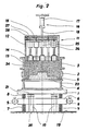
- 1, 2, 3, 4 and 5, 1 denotes a vibrating table.
- a model plate carrier 4 with a model 5, a molding frame 2 and a filling frame 3 is fastened on the vibration table 1.
- the model plate carrier 4 serves to receive a positive or a negative model plate 22.
- molding sand 24 is filled in the molding frame 2 and in the filling frame 3.
- the vibrating table 1 is supported on prestressed reactor springs 8 on an exciter frame 6.
- the exciter frame 6 itself is supported on insulation springs 7 which rest on a machine foundation 19.
- two unbalance motors 9 are arranged with opposite directions of rotation. At least one solid is on the machine foundation 19
- Stop bar 10 constructed with a support plate 20, which interacts with a support chuck 21 of the vibrating table 1.
- a vertically movable multi-punch press head 11 is provided above the vibrating table 1.
- the multi-punch press head 11 consists of three press units, the press housing 12, a mother plate 13 and a number of press punches 14. Each of these press units can be actuated individually and independently of the others.
- the press housing 12 has an outer piston / cylinder unit 16 with a pressure cylinder 17 and a pressure piston 18 and can be moved in the vertical direction.
- the mother plate 13 is slidably guided in the press housing 12 on the inner walls and is moved parallel to the direction of movement of the press housing by a plurality of inner pistons / cylinder units 25 installed in the press housing 12.
- the press rams 14 are slidably guided in the mother plate 13 parallel to the direction of movement of the mother plate 13 and are likewise moved by an inner piston / cylinder unit 26 installed in the press housing 12.
- the supply lines 27, 28 for a pressure medium to the inner piston / cylinder units 25, 26 of the press housing 12 are integrated in the cover 15 of the press housing 12.
- the sand metering device moves and the multi-stamp press head 11 moves in its place.
- a sinusoidal force acts on the vibration system consisting of the vibrating table 1, exciter frame 6, insulation springs 7 and reactor springs 8, which resonates with the rhythm of the acting force and the forced frequency, with a linear, vertical oscillating movement from the exciter frame 6 to the Vibration table 1 is transmitted.
- the ideal oscillation deflection can be set by adjusting the pretensioning force of the reactor springs 8 and the speed of the unbalance motors 9, which can be regulated continuously by means of a frequency converter (not shown).
- the molding sand 24 is fluidized by the vibration and distributed evenly in the molding frame 2, in the filling frame 3 and along the contours of the model 5.
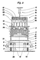
- the complete multi-punch press head 11 is lowered in the vertical direction with the aid of the piston / cylinder unit 16 and moved into the sand, the press housing 12, the mother plate 13 and the Die 14 lie in a common press plane and thus form a contour press head.
- the molding sand 24 is uniformly precompressed and vented with the multi-stamp press head 11 with an increasing pressure force of the outer piston / cylinder unit 16 with the same internal pressure of the inner piston / cylinder units 25, 26 in the press housing 12.
- the pressure forces of the hydraulic systems are set so that the resulting total deflection of the insulation springs 7 and the reactor springs 8 of the oscillating system is less than the distance between the support plate 20 of the stop beam 10 and the support chuck 21 of the vibrating table 1, ie the oscillating system vibrates freely at a high frequency without colliding with the stop beam 10.
- the frame of the press housing 12 is immersed further in the molding sand 24 by means of the outer piston / cylinder unit 16 and the press rams 14 by means of the inner piston / cylinder unit 26, while the mother plate 13 remains and the associated inner piston / cylinder units 25 are gradually compressed at a balanced pressure.
- the immersion depth of the individual press punches 14 depends on the contour of the model 5, on the characteristics of the molding sand 24 and on the inner contour of the molding box 2.
- the vibration system vibrates with compressed insulation springs 7 and reactor springs 8 still free.
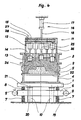
- a fourth phase the press-compression phase (see FIG. 4), the pressure in the outer piston / cylinder unit 16 and in the inner piston / cylinder units 25 assigned to the mother plate 13 is further increased, the frame of the press housing 12 and the mother plate 13 further compress the molding sand 24.
- the vibration system is based on the stop bar 10 and the frequency of the geared motors 9 is reduced; the pressing phase begins.
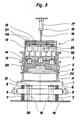
- a fifth phase the final compression phase (see FIG. 5)
- the back of the mold is pressed through the frame of the press housing with the help of the outer piston / cylinder unit 16 and the inner piston / cylinder units 25 at an optimal contact pressure with the vibration table 1 resting on the stop beam 12 and the mother plate 13 pressed until finally the lower edge of the frame of the press housing 12 falls below the parting line between the molding frame 2 and the filling frame 3 and the pressure in the outer piston / cylinder unit 16 is released via a drain valve, not shown.
- Suitable risers and pouring pits are either molded into the sand or cut into the molding sand after compaction.
- the determination of the respective amount of molding sand, the setting of the various compressive forces for the individual pressing phases, the setting of the preload of the reactor springs 8 and the changes in the drive frequencies for the unbalance motors are coordinated with the respective molding sand properties, which are carried out before each start of work using a standard test specimen using the ball impression method according to Brinell method is determined.
- press housing 12 such that individual press punches 14 or groups of press punches 14 can be acted upon separately.
- the press heads known as multi-rams, equipped with directly adjacent press rams work after a short press travel through the teeth of the sand grains (cutting angle) same as a flat press.
Priority Applications (1)
| Application Number | Priority Date | Filing Date | Title |
|---|---|---|---|
| AT89100932T ATE76341T1 (de) | 1988-02-04 | 1989-01-20 | Verfahren und vorrichtung zur durchfuehrung des verfahrens zum verdichten von giessereiformsand. |
Applications Claiming Priority (2)
| Application Number | Priority Date | Filing Date | Title |
|---|---|---|---|
| CH39688 | 1988-02-04 | ||
| CH396/88 | 1988-02-04 |
Publications (2)
| Publication Number | Publication Date |
|---|---|
| EP0326870A1 true EP0326870A1 (fr) | 1989-08-09 |
| EP0326870B1 EP0326870B1 (fr) | 1992-05-20 |
Family
ID=4186062
Family Applications (1)
| Application Number | Title | Priority Date | Filing Date |
|---|---|---|---|
| EP89100932A Expired - Lifetime EP0326870B1 (fr) | 1988-02-04 | 1989-01-20 | Procédé et dispositif de compactage de sable de fonderie |
Country Status (4)
| Country | Link |
|---|---|
| EP (1) | EP0326870B1 (fr) |
| AT (1) | ATE76341T1 (fr) |
| DE (1) | DE58901439D1 (fr) |
| ES (1) | ES2033024T3 (fr) |
Cited By (6)
| Publication number | Priority date | Publication date | Assignee | Title |
|---|---|---|---|---|
| WO2005056279A1 (fr) * | 2003-12-14 | 2005-06-23 | GEDIB Ingenieurbüro und Innovationsberatung GmbH | Dispositif pour serrer des matieres a mouler se presentant sous forme de grains |
| CN100464896C (zh) * | 2006-06-07 | 2009-03-04 | 陈岳海 | 一种铸造沙模的压模机及应用该机生产铸造沙模的方法 |
| WO2015117750A1 (fr) * | 2014-02-07 | 2015-08-13 | Schenck Process Gmbh | Machine vibrante |
| CN108500218A (zh) * | 2018-06-14 | 2018-09-07 | 临海市微能铸机有限公司 | 一种多触头压实水平分型全自动无箱造型机 |
| CN109175266A (zh) * | 2018-10-09 | 2019-01-11 | 禹州市毛吕铸造有限公司 | 一种砂型铸造压实装置 |
| CN115871081A (zh) * | 2022-11-16 | 2023-03-31 | 福建群峰机械有限公司 | 制砖机压头及双层路面砖的制砖工艺 |
Families Citing this family (2)
| Publication number | Priority date | Publication date | Assignee | Title |
|---|---|---|---|---|
| CN108856656A (zh) * | 2018-07-18 | 2018-11-23 | 安徽宏华铸造有限公司 | 一种用于电机端盖铸造的砂箱造型设备 |
| CN110744015B (zh) * | 2019-11-08 | 2020-06-30 | 湘乡市洪塘机械制造有限公司 | 一种砂型铸造模用快速填平装置 |
Citations (6)
| Publication number | Priority date | Publication date | Assignee | Title |
|---|---|---|---|---|
| DE271903C (fr) * | ||||
| US2959828A (en) * | 1958-06-30 | 1960-11-15 | Herman Pneumatic Machine Co | Foundry mold forming |
| GB912262A (en) * | 1958-10-16 | 1962-12-05 | Herman Pneumatic Machine Co | Foundry mold forming apparatus |
| US3385347A (en) * | 1966-01-24 | 1968-05-28 | Osborn Mfg Co | Jolt molding machine |
| GB2130511A (en) * | 1982-11-12 | 1984-06-06 | Gen Kinematics Corp | Method and apparatus for making foundry molds |
| GB2134426A (en) * | 1983-02-02 | 1984-08-15 | Gen Kinematics Corp | A vibratory ram compaction mold forming machine for a foundry |
-
1989
- 1989-01-20 AT AT89100932T patent/ATE76341T1/de not_active IP Right Cessation
- 1989-01-20 DE DE8989100932T patent/DE58901439D1/de not_active Expired - Fee Related
- 1989-01-20 ES ES198989100932T patent/ES2033024T3/es not_active Expired - Lifetime
- 1989-01-20 EP EP89100932A patent/EP0326870B1/fr not_active Expired - Lifetime
Patent Citations (6)
| Publication number | Priority date | Publication date | Assignee | Title |
|---|---|---|---|---|
| DE271903C (fr) * | ||||
| US2959828A (en) * | 1958-06-30 | 1960-11-15 | Herman Pneumatic Machine Co | Foundry mold forming |
| GB912262A (en) * | 1958-10-16 | 1962-12-05 | Herman Pneumatic Machine Co | Foundry mold forming apparatus |
| US3385347A (en) * | 1966-01-24 | 1968-05-28 | Osborn Mfg Co | Jolt molding machine |
| GB2130511A (en) * | 1982-11-12 | 1984-06-06 | Gen Kinematics Corp | Method and apparatus for making foundry molds |
| GB2134426A (en) * | 1983-02-02 | 1984-08-15 | Gen Kinematics Corp | A vibratory ram compaction mold forming machine for a foundry |
Cited By (8)
| Publication number | Priority date | Publication date | Assignee | Title |
|---|---|---|---|---|
| WO2005056279A1 (fr) * | 2003-12-14 | 2005-06-23 | GEDIB Ingenieurbüro und Innovationsberatung GmbH | Dispositif pour serrer des matieres a mouler se presentant sous forme de grains |
| CN100464896C (zh) * | 2006-06-07 | 2009-03-04 | 陈岳海 | 一种铸造沙模的压模机及应用该机生产铸造沙模的方法 |
| WO2015117750A1 (fr) * | 2014-02-07 | 2015-08-13 | Schenck Process Gmbh | Machine vibrante |
| AU2015215266B2 (en) * | 2014-02-07 | 2017-10-26 | Schenck Process Australia Pty Limited | Vibrating machine |
| CN108500218A (zh) * | 2018-06-14 | 2018-09-07 | 临海市微能铸机有限公司 | 一种多触头压实水平分型全自动无箱造型机 |
| CN109175266A (zh) * | 2018-10-09 | 2019-01-11 | 禹州市毛吕铸造有限公司 | 一种砂型铸造压实装置 |
| CN115871081A (zh) * | 2022-11-16 | 2023-03-31 | 福建群峰机械有限公司 | 制砖机压头及双层路面砖的制砖工艺 |
| CN115871081B (zh) * | 2022-11-16 | 2023-09-01 | 福建群峰机械有限公司 | 制砖机压头及双层路面砖的制砖工艺 |
Also Published As
| Publication number | Publication date |
|---|---|
| DE58901439D1 (de) | 1992-06-25 |
| ATE76341T1 (de) | 1992-06-15 |
| EP0326870B1 (fr) | 1992-05-20 |
| ES2033024T3 (es) | 1993-03-01 |
Similar Documents
| Publication | Publication Date | Title |
|---|---|---|
| DE102005020428A1 (de) | Anlage und Verfahren zum Herstellen von Betonwaren | |
| EP0326870B1 (fr) | Procédé et dispositif de compactage de sable de fonderie | |
| DE102005002497B3 (de) | Verfahren und Vorrichtung zum Herstellen von Hohlbausteinen | |
| DE3638207A1 (de) | Verfahren zur herstellung von betonfomsteinen und vorrichtung zur durchfuehrung des verfahrens | |
| CH642289A5 (de) | Verfahren und vorrichtung zum verdichten von giessereiformsand. | |
| DE2508074B2 (de) | Verfahren und Vorrichtung zum Formen von Erzeugnissen aus halbtrockenen, schüttbaren Massen | |
| DE648303C (de) | Ruettelformmaschine | |
| DE3004642A1 (de) | Werkstoffverdichtungsvorrichtung an betonsteinfertigungsmaschinen | |
| DE2552852C3 (de) | Verfahren zum Verdichten von Formkörpern aus Beton o.dgl. plastischen Massen | |
| DE2453634A1 (de) | Verfahren und vorrichtung zum verdichten von formkoerpern aus beton o.dgl. plastischen massen | |
| DE102011054488A1 (de) | Vorrichtung und Verfahren zur Herstellung von Betonformsteinen. | |
| DE3048181C2 (de) | Vorrichtung zum Herstellen verdichteter Formkörper aus Beton o.dgl. | |
| DE10137151C1 (de) | Vorrichtung und Verfahren zum Verdichten eines Werkstoffs | |
| EP1375098B1 (fr) | Méthode et station de remplissage pour obturer de cavités | |
| DE1963640C3 (de) | Rüttelanlage zur Herstellung von Formkörpern durch Verdichtung | |
| DE3342314C2 (fr) | ||
| CH671897A5 (en) | Moulding machine for producing sand-filled moulds - in which distribution and compaction of the sand is improved in a vibrating and compression process | |
| DE2923102A1 (de) | Verfahren zum verdichten von giessereiformsand und formmaschine zur durchfuehrung des verfahrens | |
| DE102004046147A1 (de) | Verfahren zum Herstellen von Betonsteinen | |
| DE2830479A1 (de) | Verfahren und vorrichtung zum fuellen einer form zur herstellung von formlingen aus beton o.dgl. | |
| DE3329585C2 (fr) | ||
| DE102004063272A1 (de) | Verfahren und Vorrichtung zum Verdichten eines Gemenges | |
| DE2815870A1 (de) | Vorrichtung zum verdichten von beton o.dgl. schuettfaehigen massen durch ruetteln | |
| DE923659C (de) | Verfahren und Vorrichtung zum Herstellen von Zuckerstreifen, -platten oder -wuerfeln mittels in Vibration versetzter Pressvorrichtungen | |
| EP0285821A2 (fr) | Procédé et dispositif de compactage de matériaux de moulage pour moules de fonderie |
Legal Events
| Date | Code | Title | Description |
|---|---|---|---|
| PUAI | Public reference made under article 153(3) epc to a published international application that has entered the european phase |
Free format text: ORIGINAL CODE: 0009012 |
|
| AK | Designated contracting states |
Kind code of ref document: A1 Designated state(s): AT CH DE ES FR GB IT LI SE |
|
| 17P | Request for examination filed |
Effective date: 19891216 |
|
| 17Q | First examination report despatched |
Effective date: 19910807 |
|
| GRAA | (expected) grant |
Free format text: ORIGINAL CODE: 0009210 |
|
| AK | Designated contracting states |
Kind code of ref document: B1 Designated state(s): AT CH DE ES FR GB IT LI SE |
|
| REF | Corresponds to: |
Ref document number: 76341 Country of ref document: AT Date of ref document: 19920615 Kind code of ref document: T |
|
| REF | Corresponds to: |
Ref document number: 58901439 Country of ref document: DE Date of ref document: 19920625 |
|
| GBT | Gb: translation of ep patent filed (gb section 77(6)(a)/1977) | ||
| ET | Fr: translation filed | ||
| ITF | It: translation for a ep patent filed |
Owner name: MODIANO & ASSOCIATI S.R.L. |
|
| PGFP | Annual fee paid to national office [announced via postgrant information from national office to epo] |
Ref country code: GB Payment date: 19921207 Year of fee payment: 5 |
|
| PGFP | Annual fee paid to national office [announced via postgrant information from national office to epo] |
Ref country code: FR Payment date: 19921215 Year of fee payment: 5 |
|
| PGFP | Annual fee paid to national office [announced via postgrant information from national office to epo] |
Ref country code: SE Payment date: 19921216 Year of fee payment: 5 |
|
| PGFP | Annual fee paid to national office [announced via postgrant information from national office to epo] |
Ref country code: DE Payment date: 19921221 Year of fee payment: 5 |
|
| PGFP | Annual fee paid to national office [announced via postgrant information from national office to epo] |
Ref country code: ES Payment date: 19930115 Year of fee payment: 5 |
|
| PGFP | Annual fee paid to national office [announced via postgrant information from national office to epo] |
Ref country code: AT Payment date: 19930121 Year of fee payment: 5 |
|
| REG | Reference to a national code |
Ref country code: ES Ref legal event code: FG2A Ref document number: 2033024 Country of ref document: ES Kind code of ref document: T3 |
|
| PLBE | No opposition filed within time limit |
Free format text: ORIGINAL CODE: 0009261 |
|
| STAA | Information on the status of an ep patent application or granted ep patent |
Free format text: STATUS: NO OPPOSITION FILED WITHIN TIME LIMIT |
|
| PGFP | Annual fee paid to national office [announced via postgrant information from national office to epo] |
Ref country code: CH Payment date: 19930416 Year of fee payment: 5 |
|
| 26N | No opposition filed | ||
| PG25 | Lapsed in a contracting state [announced via postgrant information from national office to epo] |
Ref country code: GB Effective date: 19940120 Ref country code: AT Effective date: 19940120 |
|
| PG25 | Lapsed in a contracting state [announced via postgrant information from national office to epo] |
Ref country code: SE Effective date: 19940121 Ref country code: ES Free format text: LAPSE BECAUSE OF NON-PAYMENT OF DUE FEES Effective date: 19940121 |
|
| PG25 | Lapsed in a contracting state [announced via postgrant information from national office to epo] |
Ref country code: LI Effective date: 19940131 Ref country code: CH Effective date: 19940131 |
|
| GBPC | Gb: european patent ceased through non-payment of renewal fee |
Effective date: 19940120 |
|
| PG25 | Lapsed in a contracting state [announced via postgrant information from national office to epo] |
Ref country code: FR Effective date: 19940930 |
|
| REG | Reference to a national code |
Ref country code: CH Ref legal event code: PL |
|
| PG25 | Lapsed in a contracting state [announced via postgrant information from national office to epo] |
Ref country code: DE Effective date: 19941001 |
|
| REG | Reference to a national code |
Ref country code: FR Ref legal event code: ST |
|
| EUG | Se: european patent has lapsed |
Ref document number: 89100932.6 Effective date: 19940810 |
|
| REG | Reference to a national code |
Ref country code: ES Ref legal event code: FD2A Effective date: 19990201 |
|
| PG25 | Lapsed in a contracting state [announced via postgrant information from national office to epo] |
Ref country code: IT Free format text: LAPSE BECAUSE OF NON-PAYMENT OF DUE FEES;WARNING: LAPSES OF ITALIAN PATENTS WITH EFFECTIVE DATE BEFORE 2007 MAY HAVE OCCURRED AT ANY TIME BEFORE 2007. THE CORRECT EFFECTIVE DATE MAY BE DIFFERENT FROM THE ONE RECORDED. Effective date: 20050120 |