EP0324924A2 - Zuführanordnung für Startbrennstoff in einer Brennkraftmaschine für tragbare Geräte - Google Patents
Zuführanordnung für Startbrennstoff in einer Brennkraftmaschine für tragbare Geräte Download PDFInfo
- Publication number
- EP0324924A2 EP0324924A2 EP88119688A EP88119688A EP0324924A2 EP 0324924 A2 EP0324924 A2 EP 0324924A2 EP 88119688 A EP88119688 A EP 88119688A EP 88119688 A EP88119688 A EP 88119688A EP 0324924 A2 EP0324924 A2 EP 0324924A2
- Authority
- EP
- European Patent Office
- Prior art keywords
- fuel
- pump
- primer pump
- metering
- passage
- Prior art date
- Legal status (The legal status is an assumption and is not a legal conclusion. Google has not performed a legal analysis and makes no representation as to the accuracy of the status listed.)
- Withdrawn
Links
Images
Classifications
-
- F—MECHANICAL ENGINEERING; LIGHTING; HEATING; WEAPONS; BLASTING
- F02—COMBUSTION ENGINES; HOT-GAS OR COMBUSTION-PRODUCT ENGINE PLANTS
- F02M—SUPPLYING COMBUSTION ENGINES IN GENERAL WITH COMBUSTIBLE MIXTURES OR CONSTITUENTS THEREOF
- F02M17/00—Carburettors having pertinent characteristics not provided for in, or of interest apart from, the apparatus of preceding main groups F02M1/00 - F02M15/00
- F02M17/02—Floatless carburettors
- F02M17/04—Floatless carburettors having fuel inlet valve controlled by diaphragm
-
- F—MECHANICAL ENGINEERING; LIGHTING; HEATING; WEAPONS; BLASTING
- F02—COMBUSTION ENGINES; HOT-GAS OR COMBUSTION-PRODUCT ENGINE PLANTS
- F02M—SUPPLYING COMBUSTION ENGINES IN GENERAL WITH COMBUSTIBLE MIXTURES OR CONSTITUENTS THEREOF
- F02M1/00—Carburettors with means for facilitating engine's starting or its idling below operational temperatures
- F02M1/16—Other means for enriching fuel-air mixture during starting; Priming cups; using different fuels for starting and normal operation
-
- Y—GENERAL TAGGING OF NEW TECHNOLOGICAL DEVELOPMENTS; GENERAL TAGGING OF CROSS-SECTIONAL TECHNOLOGIES SPANNING OVER SEVERAL SECTIONS OF THE IPC; TECHNICAL SUBJECTS COVERED BY FORMER USPC CROSS-REFERENCE ART COLLECTIONS [XRACs] AND DIGESTS
- Y10—TECHNICAL SUBJECTS COVERED BY FORMER USPC
- Y10S—TECHNICAL SUBJECTS COVERED BY FORMER USPC CROSS-REFERENCE ART COLLECTIONS [XRACs] AND DIGESTS
- Y10S261/00—Gas and liquid contact apparatus
- Y10S261/08—Carburetor primers
Definitions
- the present invention relates to a start-fuel supply device in internal combustion engines for portable equipment.
- the internal combustion engine for a portable equipment for which a small high output is required is generally of a two-cycle type provided with a diaphragm type carburetor capable of coping with a variation in an attitude of a machine body, in which when the engine is started, a proper mixture can be supplied in accordance with the operating conditions and temperature conditions.
- Japanese Patent Application Laid-Open No. 35047/1987 discloses an arrangement wherein when the engine is started, a fuel is supplied by a manual primer pump from a fuel tank to a metering chamber of a carburetor and at the same time a fuel is also filled into an accumulator, and simultaneously with the recoil operation of the engine, the fuel in the accumulator is supplied by the operation of a button from a fuel nozzle to an air intake passage of the carburetor to produce a rich mixture necessary for the start.
- an object of the present invention is to provide a start-fuel supply in an internal combustion engine for a portable equipment in which a start-fuel pump is driven by a starter motor to inject a predetermined quantity of start-fuel to an air intake passage to thereby produce a rich mixture necessary for the starting of the engine.
- the present invention provides a start-fuel pump rotatively coupled to a starter motor of the engine, a fuel metering device for reserving fuel from a metering chamber of a carburetor during the reverse rotation of the start-fuel pump, and a fuel nozzle for injecting a fuel in the fuel metering device to an air intake passage of the carburetor during the normal rotation of the fuel-start pump.
- the starter motor 46 When the starter motor 46 is then normally rotated, the engine is cranked, and the start-fuel in the metering chamber 92b of the fuel metering device 81 is injected from the fuel nozzle 14 to the air intake passage 17 of the carburetor 2 to produce a rich mixture necessary for the start so as to start the engine smoothly.
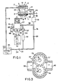
- FIG. 1 schematically shows a start-fuel supply device in an internal combustion engine according to the present invention.
- the start-fuel supply device comprises a volume type start-fuel pump 37 such as a gear pump, a vane pump or the like normally or reversely rotated by a reversible starter motor 46.
- a fuel reservoir 32 disposed between the start-fuel pump 37 and a fuel tank 35, a fuel metering device 81 disposed between the start-fuel pump 37 and a fuel nozzle 14, and the fuel nozzle 14 disposed at an air intake passage 17 of a carburetor 2.
- the starter motor 46 causes a gear 68 coupled to a shaft 67 thereof to be disengageably meshed with a gear integral with a flywheel 70 coupled to a crank shaft 69 of the internal combustion engine 27. That is, only when the starter motor 46 is normally rotated, is the gear 68 meshed with the gear of the flywheel 70, and otherwise, such an engagement therebetween is released.
- a start-fuel pump 37 is rotatably coupled to the shaft 67 of the starter motor 46.
- the motor 46 is normally and reversely rotatably connected to a battery 41 via change-over switches 55 and 56 operatively connected therewith. However, a pump switch 52 is inserted and connected to a circuit for reversing the starter motor 46, and in the case where the start-fuel need not be injected, the start-fuel pump 37 is not reversed.
- the carburetor 2 is provided at the upper portion with a fuel pump A in which a pulsating pressure is introduced into a pulse chamber 5 above a pump chamber 61 defined by a diaphragm 6.
- a fuel supply mechanism B At the lower portion of the carburetor 2 is a fuel supply mechanism B in which a metering chamber 16 and an atmospheric chamber 62 are defined by a diaphragm 11.
- fuel in the fuel tank 35 is drawn into the fuel pump A via a pipe 9 and then sent to the metering chamber 16.
- Fuel in the metering chamber 16 is drawn into the air intake passage 17 via a fuel jet, not shown, by the intake negative pressure of the air intake passage 17.
- the primer pump 37 When the primer pump 37 is normally rotated to supply fuel to the metering chamber 16, prior to starting the engine, the fuel in the metering chamber 16 is drawn into the start-fuel pump 37 via a check valve 39, a passage 40, a passage 83, the fuel metering device 81 and a passage 38, and thence moved into the passage 30 and the fuel reservoir 32. Surplus fuel is returned to the fuel tank 35 via the check valve 33 and the pipe 34. As the metering chamber 16 assumes a negative pressure state, fuel in the fuel tank 35 passes through the pipe 9 and is supplied to the metering chamber 16 via the pump chamber 61 of the fuel pump A and a passage, not shown. At this time the crank shaft 69 is not rotated.
- the start-fuel pump 37 is normally rotated by the starter motor 46, the fuel in the reservoir 32 is drawn into the start-fuel pump 37 via the passage 30, and thence fed to the fuel metering device 81 (FIG. 2) via the passage 38.
- the start-fuel in the metering chamber 92b (FIGS. 2, 4) of the fuel metering device 81 is injected into the air intake passage 17 from the fuel nozzle 14 via the passages 83, 31 and the check valve 29.
- a relief valve or a check valve 58 is provided in an outlet when the start-fuel pump 37 is normally rotated, that is, in a bypass passage 74 connecting between the side of the fuel metering device 81 and the fuel reservoir 32.
- a gear pump for example, as the primer pump 37, has a casing 73 which accommodates therein gears 77 and 79 supported on shafts 76 and 78, respectively, in meshing engagement with each other, and if one of the shafts 76 and 78 is reversely rotated (in a direction indicated by arrow) by the starter cell motor 46, fuel is drawn through the passage 38 and discharged to the passage 40 after passing around the outside of the gears 77 and 79.
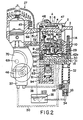
- FIG. 2 shows the mounting state of the carburetor 2 integrally provided with the fuel metering device 81, the start-fuel pump 37, the fuel reservoir 32 and the fuel nozzle 14 to the internal combustion engine 27.
- the diaphragm type carburetor 2 and an air cleaner (not shown) through an intake pipe 51 formed from a heat insulating material in communication with an intake port 66.
- the air intake passage 17 including a venturi of the body 3 is communicated with an intake port 66 provided in a cylinder 65.
- a well-known throttle valve 20 is rotatably supported by a valve shaft 19.
- a cover 4 is coupled to the upper wall of the body 3 with a diaphragm 6 disposed therebetween, and a cover 15 is coupled to the lower wall with a diaphragm 11 disposed therebetween.
- the pulsating pressure introduced into chamber 5 is connected to a crank chamber of the engine 27 through a pipe 72.
- a pump chamber 61 is connected to a pipe 9 via check valve 48, whereas the pump chamber 61 is connected to the metering chamber 16 via a check valve 47, a passage 60 and an inlet valve 10.
- An atmospheric chamber 62 between diaphragm 11 defining the metering chamber 16 and a cover 15 is open to the atmosphere by a passage 62a.
- the inlet valve 10 in the form of a needle valve is disposed on the end of the passage 60 and is opened and closed by a lever 13 supported on the wall of the metering chamber 16 by a shaft 12. Namely, one end of the lever 13 is biased into engagement with the end of the inlet valve 10 by means of the force of a spring. Th other end of the lever 13 is formed in abutment with a projection coupled to an approximate center of the diaphragm 11.
- the metering chamber 16 is connected to a high-speed fuel jet 24 via a check valve 26 and high-speed fuel metering needle valve 25.
- the metering chamber 16 is connected to a low-speed fuel jet 21 via check valve 23 and a low-speed fuel metering needle valve 22.
- the fuel metering device 81 and the fuel reservoir 32 are coupled to the underside of a cover 15.
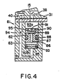
- a plunger 87 is fitted into a cylinder 82 of a body 94 thereof, and a chamber 92a is defined in the upper side thereof and a metering chamber 92b is defined in the lower side thereof.
- the chamber 92a is connected with the start-fuel pump 37 via the passage 38.
- the metering chamber 92b is connected to the metering chamber 16 via the passage 83, the check valve 39 (FIG. 2), and the passage 40, and connected with the fuel nozzle 14 via the passages 83, 31 and the check valve 29.
- a seal ring 88 to secure a liquid-tightness with the cylinder 82 is mounted on the plunger 87 with an ensmalled conical lower end 85 positioned to cooperate with a seal member 93 fitted into the cylinder 82.
- a check valve 95 is provided on the upper end of the plunger 87.
- An insert 90 has a jet bore 91 and is fitted into an open end of a cylindrical valve chamber.
- a movable valve body 89 in the form of a disk formed of rubber or the like is located within the valve chamber. The valve chamber containing the valve body 89 is connected with the metering chamber 92b via the axial passage 86, the diametrical passage in plunger 87 and a lower ensmalled diameter portion of the plunger 87.
- valve body 89 when pressed down toward the valve seat on the upper end of the passage 86, cuts off communication between the chamber 92a and the metering chamber 92b, whereas the valve body 89, when forced upward, impinges upon a plurality of projections provided on the surface encircling the jet bore 91 of the seat plate 90 to connect the chamber 92a with the metering chamber 92b.
- the fuel reservoir 32 is preferably formed from a cylindrical element made of rubber or vinyl, to the lower end of which are coupled a check valve 58 and a check valve 33.
- the check valve 33 is opened, when the fuel reservoir 32 is filled with start-fuel, to return any extra fuel to the fuel tank 35 via the passage 34.
- the check valve 58 functions to allow a flow of fuel from the passage 38 to the fuel reservoir 32, thereby to release the discharge pressure of the start-fuel pump 37 after the start-fuel has been injected into the fuel nozzle 14.
- the fuel nozzle 14 is disposed substantially in the center on the inlet side of the air intake passage 17, and a jet is directed downstream of the air intake passage 17.
- the fuel in the metering chamber 16 shown in FIG. 2 is drawn into the metering chamber 92b via the passage 40, the check valve 39 and the passage 83, and further drawn into the start-fuel pump 37 via the passage 86 of the plunger 87, the check valve 95, the jet bore 91, chamber 92a and the passage 38.
- the fuel is supplied by the start-fuel pump 37 to the fuel reservoir 32 via the passage 30.
- the extra fuel forces open the check valve 33 and is returned to the fuel tank 35 via the tube 34.
- the plunger 87 is raised by the fluid resistance of the jet bore 91 and the suction force of the start-fuel pump 37 to assume the state shown in FIG. 2.
- the start-fuel pump 37 along with the starter motor 46 are normally rotated, and the fuel in the fuel reservoir 32 shown in FIG. 2 is drawn into the start-fuel pump 37 via the passage 30.
- the fuel is fed from the start-fuel pump 37 of the chamber 92a shown in FIG. 4 via the passage 38.
- the check valve 95 is closed by the fuel pressure of the chamber 92a and the plunger 87 is forced down into abutment with the seal member 93.
- the fuel in the metering chamber 92b shown in FIG. 2 passes through the passages 83 and 31 to force open the check valve 29 and is injected from the fuel nozzle 14 into the air intake passage 17.
- the starter motor 46 When the starter motor 46 is normally rotated even after the fuel in the metering chamber 92b has been injected out of the fuel nozzle 14, the fuel discharged from the start-fuel pump 37 forces open the check valve 58 and is returned to the fuel reservoir 32. That is, the fuel in the fuel reservoir functions, during the normal rotation of the start-fuel pump 37, to force down the plunger 87 of the fuel metering device 81 by the pressure of the discharged fuel.
- the pump switch 52 remains opened, a supply of start-fuel to the fuel reservoir 32 caused by the reverse rotation of the start-fuel pump 37 is not affected, and, accordingly, even if the starter motor 46 is normally rotated, the start-fuel is not injected into the air intake passage 17.
- the seal member 88 of the plunger 87 has the liquid tightness and adequate resiliency with respect to the cylinder 82 to prevent the plunger 87 from being naturally moved downward to insure the accurate fuel metering.
- a quantity of start-fuel injected from the fuel nozzle 14 is determined according to the volume of the metering chamber 92b under the plunger 87. If the suction force is strong, the pressure in the metering chamber 16 abnormally lowers to sometimes generate a fuel vapor, and, therefore, the suction force of the plunger 87 is adjusted by the jet bore 91 provided in the plunger 87.
- the fuel reservoir 32 need not be formed of a resilient material, and the check valve 33 need not be provided.
- the check valve 33 is preferably provided.
- a start-fuel pump is rotatively coupled to a starter motor of the engine.
- a fuel metering device for reserving fuel from a metering chamber of a carburetor during the reverse rotation of the start-fuel pump, and a fuel nozzle for injecting a fuel in the fuel metering device to an air intake passage of the carburetor during the normal rotation of the fuel-start pump are provided. Therefore, the start-fuel pump is driven by the starter motor which starts the engine, and a separate motor need not be provided.
- the construction is simple, and useful for small, lightweight devices.
- start-fuel pump When the start-fuel pump is reversed by the reverse rotation of the starter motor, a predetermined quantity of start-fuel is moved into the fuel metering device, and at the same time, fuel is moved into the metering chamber.
- a predetermined quantity of start-fuel in the fuel metering device is directly injected from the fuel nozzle to the air intake passage of the carburetor during the normal rotation of the starter motor. Since the start-fuel pump is normally rotated by the starter motor having a high output, the start-fuel is injected at high pressure and quickly from the fuel nozzle to the air intake passage of the carburetor, and a rich mixture necessary for starting of the engine is rapidly supplied to the engine whereby the latter is started smoothly. Since the manual starting operation is not required as encountered in prior art, the operability is enhanced.
- the check valve is provided in the by-pass passage, after the fuel in the metering chamber of the fuel metering device has been injected out of the fuel nozzle, the fuel discharged from the start-fuel pump circulates to the fuel reservoir via the check valve of the by-pass passage, and, therefore, an abnormal rise in the discharged pressure of the start-fuel pump is prevented.
Landscapes
- Engineering & Computer Science (AREA)
- Chemical & Material Sciences (AREA)
- Combustion & Propulsion (AREA)
- Mechanical Engineering (AREA)
- General Engineering & Computer Science (AREA)
- Means For Warming Up And Starting Carburetors (AREA)
Applications Claiming Priority (2)
| Application Number | Priority Date | Filing Date | Title |
|---|---|---|---|
| JP8187/88 | 1988-01-18 | ||
| JP63008187A JPH01187352A (ja) | 1988-01-18 | 1988-01-18 | 携帯作業機用内燃機関の始動燃料供給装置 |
Publications (2)
| Publication Number | Publication Date |
|---|---|
| EP0324924A2 true EP0324924A2 (de) | 1989-07-26 |
| EP0324924A3 EP0324924A3 (de) | 1990-04-25 |
Family
ID=11686296
Family Applications (1)
| Application Number | Title | Priority Date | Filing Date |
|---|---|---|---|
| EP88119688A Withdrawn EP0324924A3 (de) | 1988-01-18 | 1988-11-25 | Zuführanordnung für Startbrennstoff in einer Brennkraftmaschine für tragbare Geräte |
Country Status (3)
| Country | Link |
|---|---|
| US (1) | US4893593A (de) |
| EP (1) | EP0324924A3 (de) |
| JP (1) | JPH01187352A (de) |
Families Citing this family (12)
| Publication number | Priority date | Publication date | Assignee | Title |
|---|---|---|---|---|
| EP0786591A3 (de) * | 1996-01-29 | 1997-08-13 | WCI OUTDOOR PRODUCTS, Inc. | Brennstoffversorgungssystem für einen schnellen Start einer Brennkraftmaschine |
| US5809975A (en) * | 1996-05-06 | 1998-09-22 | Walbro Corporation | In tank fuel pump and reservoir with stand pipe |
| DE10003736A1 (de) * | 2000-01-28 | 2001-08-02 | Bosch Gmbh Robert | Betriebseinrichtung für eine Brennkraftmaschine eines Kraftfahrzeuges mit einem Starter |
| KR100422468B1 (ko) * | 2001-07-31 | 2004-03-11 | 삼성전자주식회사 | 에스 오 아이 소자 및 그 제조방법 |
| US7967220B2 (en) * | 2002-09-13 | 2011-06-28 | Bissell Homecare, Inc. | Manual sprayer with dual bag-on-valve assembly |
| JP4261412B2 (ja) * | 2004-04-16 | 2009-04-30 | 株式会社日立製作所 | 内燃機関の燃料供給装置 |
| US7712445B2 (en) * | 2006-11-09 | 2010-05-11 | Gm Global Technology Operations, Inc. | Fuel pressure boost method and apparatus |
| US7690342B2 (en) * | 2007-01-05 | 2010-04-06 | Walbro Engine Management, L.L.C. | Priming circuit for a fuel system |
| US8001942B2 (en) * | 2007-10-31 | 2011-08-23 | GM Global Technology Operations LLC | High pressure piston pump actuating system using automotive starter system |
| US7798474B2 (en) * | 2008-03-05 | 2010-09-21 | Curtis Dyna-Fog, Ltd. | Ignition system for a pulse fog generator |
| US10465642B2 (en) | 2017-03-27 | 2019-11-05 | Kohler Co. | Carburetor drain |
| US11008978B2 (en) * | 2019-03-05 | 2021-05-18 | Kohler Co. | Bail driven stale fuel evacuation |
Family Cites Families (5)
| Publication number | Priority date | Publication date | Assignee | Title |
|---|---|---|---|---|
| US3371658A (en) * | 1966-03-17 | 1968-03-05 | Tillotson Mfg Co | Priming method and arrangement for fuel feed system |
| US4373479A (en) * | 1980-08-07 | 1983-02-15 | Outboard Marine Corporation | Fuel system providing priming and automatic warm up |
| JPS5954758A (ja) * | 1982-09-24 | 1984-03-29 | Shinagawa Diecast Kogyo Kk | 気化器の始動燃料供給装置 |
| US4508068A (en) * | 1983-06-09 | 1985-04-02 | Emerson Electric Co. | Fuel mixture enrichment system for internal combustion engine |
| JPS61157732A (ja) * | 1984-12-29 | 1986-07-17 | Daihatsu Motor Co Ltd | エンジンの始動装置 |
-
1988
- 1988-01-18 JP JP63008187A patent/JPH01187352A/ja active Pending
- 1988-11-21 US US07/273,891 patent/US4893593A/en not_active Expired - Fee Related
- 1988-11-25 EP EP88119688A patent/EP0324924A3/de not_active Withdrawn
Also Published As
| Publication number | Publication date |
|---|---|
| JPH01187352A (ja) | 1989-07-26 |
| EP0324924A3 (de) | 1990-04-25 |
| US4893593A (en) | 1990-01-16 |
Similar Documents
| Publication | Publication Date | Title |
|---|---|---|
| US4862847A (en) | Apparatus for supplying start-fuel in the internal combustion engine for a portable type working machine | |
| CA1203729A (en) | Fuel mixture enrichment system for internal combustion engine | |
| US5891369A (en) | Method and apparatus for fast start fuel system for an internal combustion engine | |
| US4893593A (en) | Start-fuel supply device in internal combustion engine for portable equipment | |
| JPH10169459A (ja) | 携帯用エンジン | |
| JPH10110652A (ja) | 膜式気化器の始動燃料供給装置 | |
| JP2546445Y2 (ja) | 一体プライマー装置を有するフロートなし気化器 | |
| US4893594A (en) | Start-fuel supply device in internal combustion engine for portable equipment | |
| US4862848A (en) | Apparatus for supplying start-fuel in the internal combustion engine for a portable type working machine | |
| US4752420A (en) | Diaphragm carburetor for internal combustion engine | |
| JPH0666235A (ja) | 内燃機関のための燃料噴射装置 | |
| WO2008070767A2 (en) | Multi-chambered fuel enrichment device | |
| JPH0310027B2 (de) | ||
| US4769185A (en) | Diaphragm carburetor for internal combustion engine | |
| JPH0649895Y2 (ja) | 内燃機関の始動補助装置 | |
| JPS6235047A (ja) | 内燃機関の始動燃料供給装置 | |
| JPH0220446Y2 (de) | ||
| JPS6260973A (ja) | 携帯作業機エンジンの始動燃料供給装置 | |
| JP2997897B2 (ja) | ダイヤフラム式気化器を備えたエンジンの始動装置 | |
| JPS6235048A (ja) | 内燃機関の始動燃料供給装置 | |
| JPS6142101B2 (de) | ||
| JPH0221577Y2 (de) | ||
| JPH01187361A (ja) | 携帯作業機用内燃機関の始動燃料供給装置 | |
| JPH01232159A (ja) | 携帯作業機用内燃機関の始動燃料供給装置 | |
| JPH01182565A (ja) | 携帯作業機用内燃機関の始動燃料供給装置 |
Legal Events
| Date | Code | Title | Description |
|---|---|---|---|
| PUAI | Public reference made under article 153(3) epc to a published international application that has entered the european phase |
Free format text: ORIGINAL CODE: 0009012 |
|
| AK | Designated contracting states |
Kind code of ref document: A2 Designated state(s): BE DE FR GB IT SE |
|
| PUAL | Search report despatched |
Free format text: ORIGINAL CODE: 0009013 |
|
| AK | Designated contracting states |
Kind code of ref document: A3 Designated state(s): BE DE FR GB IT SE |
|
| 17P | Request for examination filed |
Effective date: 19900904 |
|
| 17Q | First examination report despatched |
Effective date: 19910725 |
|
| STAA | Information on the status of an ep patent application or granted ep patent |
Free format text: STATUS: THE APPLICATION IS DEEMED TO BE WITHDRAWN |
|
| 18D | Application deemed to be withdrawn |
Effective date: 19911204 |