EP0321690A2 - Kühlluftführungs- und Ableitsystem für elektromotorisch betriebene Mundstücke - Google Patents
Kühlluftführungs- und Ableitsystem für elektromotorisch betriebene Mundstücke Download PDFInfo
- Publication number
- EP0321690A2 EP0321690A2 EP88118699A EP88118699A EP0321690A2 EP 0321690 A2 EP0321690 A2 EP 0321690A2 EP 88118699 A EP88118699 A EP 88118699A EP 88118699 A EP88118699 A EP 88118699A EP 0321690 A2 EP0321690 A2 EP 0321690A2
- Authority
- EP
- European Patent Office
- Prior art keywords
- cooling air
- electric motor
- dirt
- air
- air duct
- Prior art date
- Legal status (The legal status is an assumption and is not a legal conclusion. Google has not performed a legal analysis and makes no representation as to the accuracy of the status listed.)
- Granted
Links
Images
Classifications
-
- A—HUMAN NECESSITIES
- A47—FURNITURE; DOMESTIC ARTICLES OR APPLIANCES; COFFEE MILLS; SPICE MILLS; SUCTION CLEANERS IN GENERAL
- A47L—DOMESTIC WASHING OR CLEANING; SUCTION CLEANERS IN GENERAL
- A47L9/00—Details or accessories of suction cleaners, e.g. mechanical means for controlling the suction or for effecting pulsating action; Storing devices specially adapted to suction cleaners or parts thereof; Carrying-vehicles specially adapted for suction cleaners
- A47L9/0072—Mechanical means for controlling the suction or for effecting pulsating action
-
- A—HUMAN NECESSITIES
- A47—FURNITURE; DOMESTIC ARTICLES OR APPLIANCES; COFFEE MILLS; SPICE MILLS; SUCTION CLEANERS IN GENERAL
- A47L—DOMESTIC WASHING OR CLEANING; SUCTION CLEANERS IN GENERAL
- A47L5/00—Structural features of suction cleaners
- A47L5/12—Structural features of suction cleaners with power-driven air-pumps or air-compressors, e.g. driven by motor vehicle engine vacuum
- A47L5/22—Structural features of suction cleaners with power-driven air-pumps or air-compressors, e.g. driven by motor vehicle engine vacuum with rotary fans
- A47L5/28—Suction cleaners with handles and nozzles fixed on the casings, e.g. wheeled suction cleaners with steering handle
Definitions
- the invention relates to a cooling air guide and discharge system for electromotive mouthpieces for floor care devices, which have a separate cooling air duct of the electric motor and an independent working air duct.
- Cooling air guidance and deflection systems of this type are known in that cool ambient air is drawn in through separate air inlet slots, then guided past the components to be cooled and released again into the ambient air from a separate outlet slot.
- the dirt generated by the device e.g. Coal dust
- led to the outside via the cooling air so that this cooling air is heavily loaded with fine dust, which in turn has to be separated by means of large-area fine filters; or the ultra-fine filter must be replaced during the life of the device.
- the object of the invention is now to create a fine dust removal which avoids the need for additional technical means for separation, while avoiding the aforementioned disadvantages.
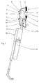
- the aforementioned upstream additional device (1) is connected to the vacuum cleaner (2) via the plug connection (15) according to FIG. 1.
- the dust-laden working air (L) is led from the floor (4) into the filter system (5) dedicated to the vacuum cleaner (2).
- the cooling air (11) is conveyed through the opening (7) in the dirt-free area (13) past the motor (6) through the negative pressure of the working air in the suction area (8) into the air duct (3). All fine dust particles emitted by the auxiliary device (1), including those from coal dust abrasion, are transferred from the electric motor (6) via the outlet openings (9) into the filter system (5) of the vacuum cleaner (2) transported and deposited there, so that no additional filter devices for the cooling air (11) of the floor care device (12) are necessary.
- the outlet openings (9) are arranged in such a way that the fine dust particles are fed directly to the suction area (8) and thus to the dirt suction opening (14) and entrained with the working air (L).
Landscapes
- Engineering & Computer Science (AREA)
- Mechanical Engineering (AREA)
- Nozzles For Electric Vacuum Cleaners (AREA)
- Duct Arrangements (AREA)
- Jet Pumps And Other Pumps (AREA)
- Motor Or Generator Cooling System (AREA)
- Cooling Or The Like Of Electrical Apparatus (AREA)
- Filtering Of Dispersed Particles In Gases (AREA)
Abstract
Description
- Die Erfindung betrifft ein Kühlluft-Führungs- und Ableitsystem für elektromotorisch betriebene Mundstücke für Bodenpflegegeräte, welche eine separate Kühlluftführung des Elektromotors und eine davon unabhängige Arbeitsluftführung aufweisen.
- Derartige Kühlluft-Führungs- und Ableitsysteme sind bekannt, indem durch separate Lufteinlaßschlitze kühle Umgebungsluft angesaugt, sodann an den zu kühlenden Bauteilen vorbeigeführt und aus einem separaten Auslaßschlitz wieder an die Umgebungsluft abgegeben wird.
- Bei den bekannten Lösungen wird der vom Gerät erzeugte Schmutz, wie z.B. Kohlestaubabrieb, über die Kühlluft nach außen geführt, so daß diese Kühlluft stark mit Feinstäuben beaufschlagt ist, die wiederum mittels großflächigen Feinstfiltern abgeschieden werden müssen; oder aber der Feinstfilter muß während der Gerätelebensdauer ausgetauscht werden.
- Die Erfindung stellt sich nun die Aufgabe, unter Vermeidung der vorgenannten Nachteile, eine Feinstaubabführung zu schaffen, die keine zusätzlichen technischen Mittel zur Abscheidung benötigt.
- Diese Aufgabe wird gemäß dem kennzeichnenden Teil des Anspruchs 1 gelöst. Eine weitere vorteilhafte Ausgestaltung ist im Anspruch 2 dargelegt.
- Die mit dieser Lösung erzielbaren Vorteile liegen insbesondere darin, daß ein mit der Erfindung ausgerüstetes Gerät oder Mundstück gänzlich ohne Zusatzfilter und ohne einen zusätzlichen Lüfter ausgestaltet werden kann. Damit ergibt sich gleichzeitig ein Vorteil für den Endbenutzer, da keinerlei Wartung mehr notwendig ist.
- Die Erfindung soll anhand der Zeichnung dargestellt werden und wird im nachfolgenden Text näher beschrieben.
- Es zeigt:
- Fig. 1: einen Schnitt durch ein Staubsaugermundstück, an welches ein Staubsauger angeschlossen ist.
- Im Zuge der Umweltdiskussion werden die Anforderungen an den Abscheidegrad der Feinstaubanteile bei elektromotorisch betriebenen Bodenpflegegeräten immer größer. Aus diesem Grund werden an derartigen Geräten normalerweise elektrostatisch arbeitende Filter oder Schwebstoffilter dem eigentlichen Filtriervorgang nachgeordnet.
- Um für das komplette Bodenpflegesystem, z.B. einen Staubsauger (2) mit vorgeschaltetem Zusatzgerät (1), eine befriedigende Lösung zu schaffen, wird nach Fig. 1 das vorgenannte vorgeschaltete Zusatzgerät (1) mit dem Staubsauger (2) über die Steckverbindung (15) verbunden. Über den Arbeitsluft-Kanal (3) wird die staubbeladene Arbeitsluft (L) vom Boden (4) in das dem Staubsauger (2) eigene Filtersystem (5) geführt.
- Zur Kühlung des Motors (6) wird durch eine Öffnung (7) im schmutzfreien Bereich (13) die Kühlluft (11) am Motor (6) vorbei durch den Unterdruck der Arbeitsluft im Saugbereich (8) in den Luftkanal (3) befördert. Dabei werden alle vom Zusatzgerät (1) emittierten Feinstaubpartikel, auch z.B. die des Kohlestaubabriebes, vom Elektromotor (6) über die Austrittsöffnungen (9) in das Filtersystem (5) des Staubsaugers (2) transportiert und dort abgeschieden, so daß keine zusätzlichen Filtereinrichtungen für die Kühlluft (11) des Bodenpflegegeräts (12) notwendig sind.
- Die Austrittsöffnungen (9) sind derart angeordnet, daß die Feinstaubpartikel direkt dem Saugbereich (8) und somit der Schmutzansaugöffnung (14) zugeführt und mit der Arbeitsluft (L) mitgerissen werden.
Claims (2)
Priority Applications (1)
| Application Number | Priority Date | Filing Date | Title |
|---|---|---|---|
| AT88118699T ATE91605T1 (de) | 1987-12-19 | 1988-11-10 | Kuehlluftfuehrungs- und ableitsystem fuer elektromotorisch betriebene mundstuecke. |
Applications Claiming Priority (2)
| Application Number | Priority Date | Filing Date | Title |
|---|---|---|---|
| DE8716760U | 1987-12-19 | ||
| DE8716760U DE8716760U1 (de) | 1987-12-19 | 1987-12-19 | Kühlluft-Führungs- und Ableitvorrichtung für elektromotorisch betriebene Mundstücke |
Publications (3)
| Publication Number | Publication Date |
|---|---|
| EP0321690A2 true EP0321690A2 (de) | 1989-06-28 |
| EP0321690A3 EP0321690A3 (de) | 1991-04-17 |
| EP0321690B1 EP0321690B1 (de) | 1993-07-21 |
Family
ID=6815307
Family Applications (1)
| Application Number | Title | Priority Date | Filing Date |
|---|---|---|---|
| EP88118699A Expired - Lifetime EP0321690B1 (de) | 1987-12-19 | 1988-11-10 | Kühlluftführungs- und Ableitsystem für elektromotorisch betriebene Mundstücke |
Country Status (4)
| Country | Link |
|---|---|
| EP (1) | EP0321690B1 (de) |
| AT (1) | ATE91605T1 (de) |
| DE (2) | DE8716760U1 (de) |
| ES (1) | ES2041767T3 (de) |
Cited By (3)
| Publication number | Priority date | Publication date | Assignee | Title |
|---|---|---|---|---|
| EP0547423A1 (de) * | 1991-12-17 | 1993-06-23 | Vorwerk & Co. Interholding GmbH | Mundstück für eine Poliermaschine |
| US6481050B1 (en) | 2000-07-19 | 2002-11-19 | The Hoover Company | Motor-fan cooling air directed into filter bag |
| US8533906B2 (en) | 2011-07-07 | 2013-09-17 | Shop Vac Corporation | Vacuum cleaner with recirculated cooling air |
Families Citing this family (1)
| Publication number | Priority date | Publication date | Assignee | Title |
|---|---|---|---|---|
| GB0008370D0 (en) | 2000-04-06 | 2000-05-24 | Reckitt & Colmann Prod Ltd | Improvements in or relating to electric appliances |
Family Cites Families (5)
| Publication number | Priority date | Publication date | Assignee | Title |
|---|---|---|---|---|
| US2561964A (en) * | 1946-01-30 | 1951-07-24 | Landers Frary & Clark | Air-flow control for vacuum cleaners |
| DE1823021U (de) * | 1960-05-11 | 1960-12-08 | Vorwerk & Co Elektrowerke Kg | Elektro-teppichbuerste. |
| FR1257576A (fr) * | 1960-05-27 | 1961-03-31 | Vorwerk & Co Elektrowerke Kg | Appareil brosseur électrique pour tapis |
| FR1377614A (fr) * | 1963-10-09 | 1964-11-06 | Thomson Houston Comp Francaise | Aspirateur de poussières |
| DE2519155A1 (de) * | 1975-04-30 | 1976-11-11 | Vorwerk & Co Elektrowerke Kg | Gehaeuse fuer bodenpflegegeraete, insbesondere fuer teppichkehrmaschinen |
-
1987
- 1987-12-19 DE DE8716760U patent/DE8716760U1/de not_active Expired
-
1988
- 1988-11-10 AT AT88118699T patent/ATE91605T1/de not_active IP Right Cessation
- 1988-11-10 EP EP88118699A patent/EP0321690B1/de not_active Expired - Lifetime
- 1988-11-10 DE DE8888118699T patent/DE3882501D1/de not_active Expired - Fee Related
- 1988-11-10 ES ES198888118699T patent/ES2041767T3/es not_active Expired - Lifetime
Cited By (3)
| Publication number | Priority date | Publication date | Assignee | Title |
|---|---|---|---|---|
| EP0547423A1 (de) * | 1991-12-17 | 1993-06-23 | Vorwerk & Co. Interholding GmbH | Mundstück für eine Poliermaschine |
| US6481050B1 (en) | 2000-07-19 | 2002-11-19 | The Hoover Company | Motor-fan cooling air directed into filter bag |
| US8533906B2 (en) | 2011-07-07 | 2013-09-17 | Shop Vac Corporation | Vacuum cleaner with recirculated cooling air |
Also Published As
| Publication number | Publication date |
|---|---|
| DE8716760U1 (de) | 1988-04-07 |
| ES2041767T3 (es) | 1993-12-01 |
| EP0321690A3 (de) | 1991-04-17 |
| DE3882501D1 (de) | 1993-08-26 |
| ATE91605T1 (de) | 1993-08-15 |
| EP0321690B1 (de) | 1993-07-21 |
Similar Documents
| Publication | Publication Date | Title |
|---|---|---|
| EP3033983B1 (de) | Basisstation für einen staubsauger | |
| DE3045392C2 (de) | ||
| DE2856058C2 (de) | Offenendspinneinheit | |
| DE2211934A1 (de) | Verfahren zum Abführen von Verun reinigungen auf Stapelfasern, die aus einer Vereinzelungsvorrichtung kommen | |
| EP0321690B1 (de) | Kühlluftführungs- und Ableitsystem für elektromotorisch betriebene Mundstücke | |
| DE2213006A1 (de) | Spindellose Spinnmaschine | |
| DE2627117A1 (de) | Austragseinrichtung fuer filtermaterial | |
| DE102018128757A1 (de) | Verfahren und Vorrichtung zum Betrieb einer Metall-Druckeinrichtung | |
| DE3219391A1 (de) | Schmutzsauger | |
| DE1213320B (de) | Faden- und Staubabsaugung fuer Spinnmaschinen | |
| EP0062781B1 (de) | Offenendspinnmaschine | |
| DE102015010520A1 (de) | Textilmaschine und Verfahren zum Nutzen von Absaugluft an Arbeitsstellen der Textilmaschinen | |
| DE2907747A1 (de) | Pneumatische reinigungseinrichtung am einlauftisch einer spinnereimaschine | |
| WO1999005915A2 (de) | Verfahren und vorrichtung zur pneumatischen handhabung von waffelblättern | |
| DE897044C (de) | Schlauchfilter | |
| DE1796146U (de) | Kombinierte abblase- und absauganlage fuer flyer. | |
| EP0532457A1 (de) | Textilmaschine mit sog. Flug erzeugenden Bearbeitungselementen | |
| DE553753C (de) | Fliehkraftstaubabscheider | |
| EP4596054A1 (de) | Gebläsefiltergerät und gebläsefiltersystem | |
| DE807297C (de) | Absauggeblaese mit Vorkammer | |
| AT221399B (de) | Faden- und Staubabsaugvorrichtung für Spinnmaschinen | |
| DE1685860C3 (de) | Verfahrbare Reinigungsvorrichtung bei Textilmaschinen | |
| DE102021204246A1 (de) | Raumluftreinigungsvorrichtung mit Gehäuse-Filter-Einheit | |
| EP0556604A1 (de) | Schuh-Ausputzmaschine | |
| EP0448131A2 (de) | Atemschutzmaske |
Legal Events
| Date | Code | Title | Description |
|---|---|---|---|
| PUAI | Public reference made under article 153(3) epc to a published international application that has entered the european phase |
Free format text: ORIGINAL CODE: 0009012 |
|
| AK | Designated contracting states |
Kind code of ref document: A2 Designated state(s): AT BE CH DE ES FR GB IT LI NL SE |
|
| PUAL | Search report despatched |
Free format text: ORIGINAL CODE: 0009013 |
|
| AK | Designated contracting states |
Kind code of ref document: A3 Designated state(s): AT BE CH DE ES FR GB IT LI NL SE |
|
| 17P | Request for examination filed |
Effective date: 19910708 |
|
| 17Q | First examination report despatched |
Effective date: 19920224 |
|
| GRAA | (expected) grant |
Free format text: ORIGINAL CODE: 0009210 |
|
| AK | Designated contracting states |
Kind code of ref document: B1 Designated state(s): AT BE CH DE ES FR GB IT LI NL SE |
|
| REF | Corresponds to: |
Ref document number: 91605 Country of ref document: AT Date of ref document: 19930815 Kind code of ref document: T |
|
| REF | Corresponds to: |
Ref document number: 3882501 Country of ref document: DE Date of ref document: 19930826 |
|
| ET | Fr: translation filed | ||
| ITF | It: translation for a ep patent filed | ||
| GBT | Gb: translation of ep patent filed (gb section 77(6)(a)/1977) |
Effective date: 19931020 |
|
| ITTA | It: last paid annual fee | ||
| REG | Reference to a national code |
Ref country code: ES Ref legal event code: FG2A Ref document number: 2041767 Country of ref document: ES Kind code of ref document: T3 |
|
| PLBE | No opposition filed within time limit |
Free format text: ORIGINAL CODE: 0009261 |
|
| STAA | Information on the status of an ep patent application or granted ep patent |
Free format text: STATUS: NO OPPOSITION FILED WITHIN TIME LIMIT |
|
| 26N | No opposition filed | ||
| EAL | Se: european patent in force in sweden |
Ref document number: 88118699.3 |
|
| PGFP | Annual fee paid to national office [announced via postgrant information from national office to epo] |
Ref country code: GB Payment date: 19960913 Year of fee payment: 9 |
|
| PGFP | Annual fee paid to national office [announced via postgrant information from national office to epo] |
Ref country code: SE Payment date: 19960916 Year of fee payment: 9 |
|
| PGFP | Annual fee paid to national office [announced via postgrant information from national office to epo] |
Ref country code: FR Payment date: 19960924 Year of fee payment: 9 |
|
| PGFP | Annual fee paid to national office [announced via postgrant information from national office to epo] |
Ref country code: BE Payment date: 19960930 Year of fee payment: 9 |
|
| PGFP | Annual fee paid to national office [announced via postgrant information from national office to epo] |
Ref country code: CH Payment date: 19961101 Year of fee payment: 9 |
|
| PGFP | Annual fee paid to national office [announced via postgrant information from national office to epo] |
Ref country code: ES Payment date: 19961111 Year of fee payment: 9 |
|
| PGFP | Annual fee paid to national office [announced via postgrant information from national office to epo] |
Ref country code: AT Payment date: 19961128 Year of fee payment: 9 |
|
| PGFP | Annual fee paid to national office [announced via postgrant information from national office to epo] |
Ref country code: DE Payment date: 19961129 Year of fee payment: 9 |
|
| PGFP | Annual fee paid to national office [announced via postgrant information from national office to epo] |
Ref country code: NL Payment date: 19961130 Year of fee payment: 9 |
|
| PG25 | Lapsed in a contracting state [announced via postgrant information from national office to epo] |
Ref country code: GB Free format text: LAPSE BECAUSE OF NON-PAYMENT OF DUE FEES Effective date: 19971110 Ref country code: AT Free format text: LAPSE BECAUSE OF NON-PAYMENT OF DUE FEES Effective date: 19971110 |
|
| PG25 | Lapsed in a contracting state [announced via postgrant information from national office to epo] |
Ref country code: SE Free format text: LAPSE BECAUSE OF NON-PAYMENT OF DUE FEES Effective date: 19971111 Ref country code: ES Free format text: LAPSE BECAUSE OF EXPIRATION OF PROTECTION Effective date: 19971111 |
|
| PG25 | Lapsed in a contracting state [announced via postgrant information from national office to epo] |
Ref country code: LI Free format text: LAPSE BECAUSE OF NON-PAYMENT OF DUE FEES Effective date: 19971130 Ref country code: FR Free format text: THE PATENT HAS BEEN ANNULLED BY A DECISION OF A NATIONAL AUTHORITY Effective date: 19971130 Ref country code: CH Free format text: LAPSE BECAUSE OF NON-PAYMENT OF DUE FEES Effective date: 19971130 Ref country code: BE Free format text: LAPSE BECAUSE OF NON-PAYMENT OF DUE FEES Effective date: 19971130 |
|
| BERE | Be: lapsed |
Owner name: VORWERK & CO. INTERHOLDING G.M.B.H. Effective date: 19971130 |
|
| PG25 | Lapsed in a contracting state [announced via postgrant information from national office to epo] |
Ref country code: NL Free format text: LAPSE BECAUSE OF NON-PAYMENT OF DUE FEES Effective date: 19980601 |
|
| GBPC | Gb: european patent ceased through non-payment of renewal fee |
Effective date: 19971110 |
|
| REG | Reference to a national code |
Ref country code: CH Ref legal event code: PL |
|
| PG25 | Lapsed in a contracting state [announced via postgrant information from national office to epo] |
Ref country code: DE Free format text: LAPSE BECAUSE OF NON-PAYMENT OF DUE FEES Effective date: 19980801 |
|
| EUG | Se: european patent has lapsed |
Ref document number: 88118699.3 |
|
| NLV4 | Nl: lapsed or anulled due to non-payment of the annual fee |
Effective date: 19980601 |
|
| REG | Reference to a national code |
Ref country code: FR Ref legal event code: ST |
|
| REG | Reference to a national code |
Ref country code: ES Ref legal event code: FD2A Effective date: 20010301 |
|
| PG25 | Lapsed in a contracting state [announced via postgrant information from national office to epo] |
Ref country code: IT Free format text: LAPSE BECAUSE OF NON-PAYMENT OF DUE FEES;WARNING: LAPSES OF ITALIAN PATENTS WITH EFFECTIVE DATE BEFORE 2007 MAY HAVE OCCURRED AT ANY TIME BEFORE 2007. THE CORRECT EFFECTIVE DATE MAY BE DIFFERENT FROM THE ONE RECORDED. Effective date: 20051110 |