EP0321404B1 - Vorrichtung zur Steuerung und Regelung der Arbeitsweise einer Spinnmaschine bei einem System zum Austausch von Vorlagespulen - Google Patents
Vorrichtung zur Steuerung und Regelung der Arbeitsweise einer Spinnmaschine bei einem System zum Austausch von Vorlagespulen Download PDFInfo
- Publication number
- EP0321404B1 EP0321404B1 EP88810846A EP88810846A EP0321404B1 EP 0321404 B1 EP0321404 B1 EP 0321404B1 EP 88810846 A EP88810846 A EP 88810846A EP 88810846 A EP88810846 A EP 88810846A EP 0321404 B1 EP0321404 B1 EP 0321404B1
- Authority
- EP
- European Patent Office
- Prior art keywords
- roving
- circuit
- signal
- spinning
- spinning frame
- Prior art date
- Legal status (The legal status is an assumption and is not a legal conclusion. Google has not performed a legal analysis and makes no representation as to the accuracy of the status listed.)
- Expired
Links
- 238000009987 spinning Methods 0.000 title claims description 126
- 238000013459 approach Methods 0.000 claims description 29
- 238000012790 confirmation Methods 0.000 claims description 15
- 238000001514 detection method Methods 0.000 description 4
- 238000010586 diagram Methods 0.000 description 3
- 238000000034 method Methods 0.000 description 3
- 238000004804 winding Methods 0.000 description 3
- 238000010276 construction Methods 0.000 description 2
- 238000006073 displacement reaction Methods 0.000 description 2
- 238000007796 conventional method Methods 0.000 description 1
- 230000000881 depressing effect Effects 0.000 description 1
- 239000000463 material Substances 0.000 description 1
- 238000005259 measurement Methods 0.000 description 1
- 238000004806 packaging method and process Methods 0.000 description 1
- 239000011295 pitch Substances 0.000 description 1
- 238000010977 unit operation Methods 0.000 description 1
Images

Classifications
-
- D—TEXTILES; PAPER
- D01—NATURAL OR MAN-MADE THREADS OR FIBRES; SPINNING
- D01H—SPINNING OR TWISTING
- D01H9/00—Arrangements for replacing or removing bobbins, cores, receptacles, or completed packages at paying-out or take-up stations ; Combination of spinning-winding machine
- D01H9/005—Arrangements for replacing or removing bobbins, cores, receptacles, or completed packages at paying-out or take-up stations ; Combination of spinning-winding machine for removing empty packages or cans and replacing by completed (full) packages or cans at paying-out stations; also combined with piecing of the roving
-
- D—TEXTILES; PAPER
- D01—NATURAL OR MAN-MADE THREADS OR FIBRES; SPINNING
- D01H—SPINNING OR TWISTING
- D01H13/00—Other common constructional features, details or accessories
- D01H13/14—Warning or safety devices, e.g. automatic fault detectors, stop motions ; Monitoring the entanglement of slivers in drafting arrangements
- D01H13/24—Warning or safety devices, e.g. automatic fault detectors, stop motions ; Monitoring the entanglement of slivers in drafting arrangements responsive to delivery of a measured length of material, completion of winding of a package or filling of a receptacle
Definitions
- the present invention relates to an apparatus for controlling the operation of a spinning frame in relation to a roving bobbin exchange system, wherein almost exhausted roving bobbins of bobbin hangers of a creel of a spinning frame are intermittently exchanged for corresponding full packaged roving bobbins suspended by bobbin hangers of a bobbin carriage carried to a working position thereof on a supply rail arranged along the longitudinal direction of the spinning frame, by means of a roving bobbin exchange apparatus which is capable of moving along a spindle rail of the spinning frame, in parallel to the operation for piecing rovings between a starting-end of a roving of each full packaged roving bobbin being subjected to the roving bobbin exchange operation with a rear end of roving from a corresponding almost exhausted roving bobbin which is still supplying the roving to the spinning frame.
- the following apparatuses can be utilized as the above-mentioned roving bobbin exchange apparatus.
- the apparatus as disclosed in European Laid-open Patent Publication No. 0213962, which corresponds to Japanese Unexamined Patent Publication Sho 62-53425, whereby the roving bobbin exchange operation is applied to a spinning frame.
- this spinning system at the starting condition, half exhausted roving bobbins are suspended by respective back-row bobbin hangers in a creel of each spinning frame while full packaged roving bobbins are suspended by respective front-row of bobbin hangers in the creel, and therefore, when the
- the almost exhausted roving bobbins are exchanged for roving bobbins having packaging condition of which has changed from full size to half size.
- all roving bobbins on the front row of the creel are exchanged for facing roving bobbins on the back row of the creel, to suspended all of the almost exhausted roving bobbins by the respective front row of bobbin hangers of the creel, and thereafter, the above-mentioned roving bobbin exchange operation is carried out and the almost exhausted roving bobbins of the front row of bobbin hangers in the creel of the spinning frame are intermittently exchanged for corresponding full packaged roving bobbins of the bobbin hangers on the bobbin carriage on the supply rail, from one end of the spinning frame to the other end thereof along the spindle rail during the spinning operation, in parallel to the operation for piecing
- a unit operation applied to plural adjacent pair of a front and back bobbin hangers of the creel, facing each other, of the spinning frame is intermittently carried out from one end of the spinning frame to the other end thereof.
- half exhausted roving bobbins and full packaged roving bobbins are alternately suspended by the front row and the back row of the bobbin hangers in the creel of the spinning frame, respectively, in a condition such that each front row bobbin hanger suspending a half exhausted roving bobbin faces a corresponding back row bobbin hanger suspending a half exhausted roving bobbin, while each front row bobbin hanger suspending a full packaged roving bobbin faces a corresponding back row bobbin hanger suspending a full packaged roving bobbin, at the start of the spinning operation.
- each pair of such almost exhausted roving bobbins suspended by a corresponding front row bobbin hanger and back row bobbin hanger, facing each other are exchanged for full packaged roving bobbins of the bobbin carriage on the supply rail, in parallel to the operation for piecing a starting-end of a roving of each full packaged roving bobbin being subjected to the roving bobbin exchange operation with a rear-end of a roving from the corresponding almost exhausted roving bobbin which is still supplying a roving to the spinning frame.
- a signal is output to request a roving bobbin exchange operation from the spinning frames, accordingly, the consumed condition of roving bobbins suspended by the bobbin hangers of the creel of the spinning frame is measured in each spinning frame, and when the size of the roving bobbins in the half exhausted condition reaches the almost exhausted condition in a certain spinning frame, the above-mentioned request signal is output from this spinning frame to call the roving bobbin exchange apparatus, as disclosed in Japanese Unexamined Patent Publication Sho 62-62929.
- the present invention relates to an apparatus for controlling an operation of a spinning frame in a roving bobbin exchange system, to solve the above-mentioned problem of the conventional roving bobbin exchange system.
- a roving bobbin exchange system wherein the roving bobbin exchange operation is carried out in parallel to the above-mentioned piecing operation, according to the present invention, there is provided an
- apparatus for controlling the operation of a spinning frame which comprises means for outputting a first signal indicating a residual quantity of a roving on a roving bobbin, based upon a measurement of the quantity of roving supplied from the roving bobbins which correspond to the above-mentioned half exhausted roving bobbins, means for outputting a second signal demanding an application of the roving bobbin exchanging operation, based upon the detection of a pertinent condition for carrying out the bobbin exchange operation by measuring the quantity of yarn produced, these two means being disposed on each spinning frame, and a control circuit for outputting a calling signal for calling the roving bobbin exchange apparatus based upon the logical product of the first and second signals.
- An approach confirmation switch for confirming the approach of the roving bobbin exchange apparatus to a working position thereof close to a spinning frame which has output the above-mentioned calling signal, and means for setting an allowable time to the roving bobbin exchange apparatus from a time, that the above-mentioned calling signal is output, to a time at which the roving bobbin exchange apparatus starts to carry out the roving exchange operation, are involved in the above-mentioned control circuit, so that if the confirmation switch does not output a confirm signal after the above-mentioned calling signal is output within the above-mentioned allowable time, the drive motor of the spinning frame which has output the calling signal is stopped.
- the roving bobbin exchange apparatus does not arrive at the working position thereof in the proximity of a spinning frame from which the above-mentioned calling signal has been output, within the above-mentioned allowable time, the drive of the spinning frame is stopped so that the roving bobbins, which became to almost exhausted condition, still carry a residual roving thereon which is necessary for carrying out the piecing thereof with a starting end of a roving of the full packaged roving bobbins. Accordingly, the above-mentioned problem of the conventional roving bobbin exchange system can be solved.
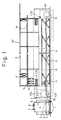
- a plurality of spinning frames SF are installed on a floor of a spinning factory as a group G.
- a track 1 composed of a pair of parallel rails is laid out on the floor along the frame-ends of the spinning frames SF of the group G, and a carrier 2 is movably arranged on the track 1 so that the direction of the carrier 2 is reversed at both end terminals of the track 1.
- the carrier 2 is constructed so that, when it is confirmed that a lamp L is lit during the displacing motion of the carrier 2, the carrier 2 is stopped at a working position facing the frame-end of the spinning frame SF concerned. As shown in Fig.
- loading rails 3 for loading an apparatus 4 for exchanging roving bobbins thereon are rigidly disposed at both sides of the carrier 2, and rotary wheels 5 of the apparatus 4 are rotatably mounted on the loading rails 3, respectively, to support the apparatus 4.
- Bridge rails 6 to be connected to guide rails, described hereinafter, of the spinning frame SF are attached to the front of the loading rails 3. As shown in Figs.
- supply rails 9 are arranged along the corresponding spinning frames SF, at a position close thereto and slightly higher than the top of each spinning frame SF, respectively, and connected at the ends thereof to a main rail 10, as shown in Fig. 2, and this main rail 10 is extended to the working position close to a group of roving frames (not shown) so that bobbin carriages (not shown) are able to transport roving bobbins (empty or full package condition) between the working places of the bobbin carrier 2 close to the spinning frames SF and the working places thereof close to the roving frames.
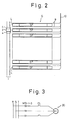
- each spinning frame SF is provided with an automatic doffing and donning device 12 which is able to simultaneously doff full packaged cops from all spindles 11 f one side of the frame and simultaneously don fresh bobbins on these spindles 11, by utilizing a doffing and donning bar 13, as shown in U.S. Patent No. 3905184.
- each spinning frame SF is provided with a guide rail 14, which extends from an out-end to a gear end of the frame SF, at each side thereof.
- a limit switch LS1 by which the arrival of the roving exchanging apparatus 4 is confirmed
- a second limit switch LS2 by which the completion of the roving bobbin exchange operation is confirmed, by the engagement thereof with the apparatus 4 that has reached that position.
- a drive motor M1 for driving each spinning frame SF is disposed at an out-end frame thereof, so that the drive power of this motor M1 is transferred to a group of drafting rollers 16 via several gear trains disposed in a gear-end frame, by a main shaft 15 connected to the motor M1.
- a first detecting switch PS1 which detects a predetermined length of yarn produced by the spinning frame SF, by closing a contact (for example, a pulser which issues one pulse upon each detection of a predetermined number of rotations of a front roller 17) is connected to the front roller 17.
- the lamp L which is lit to indicate that a call has been made for the automatic roving bobbin exchange apparatus 4, is mounted on the gear-end frame of each spinning frame SF.
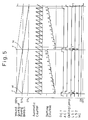
- the call lamp L, the first limit switch LS1, the second limit switch LS2, and the first detection switch PS1 are electrically connected to a control circuit 20.
- a circuit (1) is a main motor starting and stopping circuit, including a relay MS1 for a main motor circuit 30 (see Fig. 3), and in this circuit (1), time limiting contacts TR1-1 and TR2-1 of timers TR1 and TR2 described hereinafter are connected in series, and a contact RY4-1 of an auxiliary relay RY4 described hereinafter and a timer contact TR3- are connected in series in parallel to a push button switch PB1.
- a circuit (2) is a cop wound quantity indicating circuit for indicating that the wound quantity of cops of the spinning frame SF has reached a suitable condition for an exchange of roving bobbins.
- the contact of the detecting switch PS1 is connected to a counting input of a known automatic counter AC and has a contact RYA, which is closed during an operation of preparing for a doffing (for example, a downwards displacement of a ring rail after the cop becomes full), connected to a reset input of the counter AC, whereby a cop wound quantity indicating means outputs a bobbin exchange signal (first signal), by closing a counter contact AC1 arranged in the control circuit 20 when the detection switch PS1 detects a predetermined wound quantity suitable for a bobbin exchange.
- the predetermined wound quantity is set at a wound quantity obtained after an elapse of a predetermined time from the empty condition of bobbins for winding yarn, for example, 20% of a full size when producing a yarn having a coarse count and 40% of a full size when producing a yarn having a medium count, whereby, if the normal
- the automatic counter AC is a two-preset-value counter in which the above-mentioned predetermined wound quantity and the fully wound quantity are preset as set values.
- a circuit (3) is a doffing counter circuit including a doffing counter DC, and in this circuit (3), a contact RYB, which is closed by a doffing instruction output issued by the above-mentioned automatic counter AC, is connected to a counting input of the doffing counter DC when the wound quantity reaches the fully wound quantity, and an a-contact RY3-1 of a roving bobbin exchange confirming relay RY3 described hereinafter is connected to a resetting input of the doffing counter DC, whereby a residual roving quantity indicating means for outputting a bobbin exchange signal (second signal) by closing a counter contact DC1 arranged in this circuit when the doffing counter DC detecting the supplied roving quantity, detects that the amount of residual roving of the roving bobbin in the creel is approaching the predetermined wound quantity suitable for requesting a bobbin exchange operation.
- the predetermined wound quantity of the roving bobbin is set, for example, to 1/2 of the possible number of full packaged cops which can be produced by one full packaged roving bobbin. For example, where one full packaged roving bobbin can produce 22 full packaged cops, the set value is 11.
- a circuit (4) is a circuit for calling the roving bobbin exchange apparatus in which the counter contact AC1 of the automatic counter AC, the counter contact DC1 of the doffing counter DC, and the calling lamp L are connected in series, and an auxiliary relay RY1 is connected in parallel to the calling lamp L, so that when both of the above-mentioned counter contacts AC1 and DC1 are closed (i.e., a logical product is taken), the calling lamp L is lit.
- a circuit (5) is an allowable approach time setting circuit including the timer TRI (time setting means) for setting an allowable approach time T as the set time value.
- This allowable approach time T is set so that if the roving bobbin exchange apparatus 4 approaches the spinning frame SF within this allowable time T after the output of the calling signal and the normal bobbin exchange operation is started, the bobbin exchange operation is completed within a time such that the spinning bobbin does not become a full package and the roving bobbin does not reach an exhausted condition.
- An a-contact of RYI-1 of the auxiliary relay RY1 and a b-contact RY2-1 of an approach confirming relay RY2 described hereinafter are connected in series to the timer input of the timer TR1, so that counting is started simultaneously with the output of the calling signal in the circuit (4).
- An a-contact RY2-2 of the approach confirming relay RY2 is connected to the reset input of the timer TR1.
- a circuit (6) is an approach confirmation circuit for connecting the approach confirmation switch (first limit switch) LS1 to the approach confirmation relay (b-contact relay) RY2, and while the apparatus 4 approaches the spinning frame SF, the contact of the approach confirmation switch LS1 is kept closed.
- a circuit (7) is a circuit for confirming the completion of the bobbin exchange operation, and includes the bobbin exchange confirmation switch(a second limit switch) LS2, a contact RY2-2 and, the roving bobbin exchange confirming relay RY3.
- a circuit (8) is an allowable bobbin exchange time setting circuit including the timer TR2 for setting an allowable bobbin exchange time as the set time value, and an a-contact RY2-4 of the approach confirmation relay RY2 and a b-contact RY3-2 of the above-mentioned relay RY3 are connected to the timer input of the timer TR2 so that
- An a-contact RY3-3 of the above-mentioned relay RY3 is connected to the reset input of the timer TR2, so that when the second limit switch LS2 in the circuit 7 is turned ON (bobbin exchange completion signal output), the timer TR2 is reset.
- the allowable bobbin exchange time of the timer TR2 is set at a normal operation time of the apparatus 4, i.e., the time of the bobbin exchange operation which is carried out without problems.
- a circuit (9) is a re-starting signal output circuit including the auxiliary relay (a driving motor re-starting relay) RY4, and a circuit (10) is a re-starting signal cutting circuit including a timer TR3 in which the time count is completed after the lapse of a predetermined time from the time of re-starting the drive motor M.
- each spinning frame SF to which the present invention is applied at the time of starting the spinning operation, full packaged roving bobbins and half exhausted roving bobbins are alternately suspended by bobbin hangers of a front row 19a and a back row 19b in the creel 19 of each spinning frame SF, in a condition such that each front bobbin hanger and each back bobbin hanger, facing each other, is suspending roving bobbins in an identical roving winding condition.
- the half-exhausted roving bobbin is hereinafter referred to as M.
- the medium-roving bobbin M When the counted value reaches the preset value 11, the medium-roving bobbin M has become an almost exhausted roving bobbin S (the quantity of residual roving is about 5%) which condition is suitable for carrying out roving bobbin exchange operation by the apparatus 4.
- the counter contact DC1 of the circuit 4 is closed as the first signal to request bobbin exchange operation, and when the count value of the automatic counter AC reaches the set value suitable for the bobbin exchange (for example, the value corresponding to 1/4 of the fully wound quantity) (at this point, the amount of the residual roving is about 2%, and this value is substantially the quantity of the residual roving to be exchanged), the counting is terminated and the counter contact AC1 of the circuit 4 is closed as the second signal to request bobbin exchange operation, whereby the logical product of these two bobbin exchange signals is created and the calling lamp L of the circuit 4 is lit as the calling signal and the auxiliary relay RY1 is turned ON.
- the set value suitable for the bobbin exchange for example, the value corresponding to 1/4 of the fully wound quantity
- the AND operation of the first and second signals is logically conducted to form the calling signal, whereby the calling lamp L of the circuit 4 is lit, and simultaneously, the auxiliary relay RY1 is turned ON. During this period, spinning of the spinning frame SF is continued. At this time, the a-contact RY1-1 of the circuit 5 is closed, and since
- the timer TR1 begins counting. If the carrier 2 is carrying the roving bobbin exchange apparatus 4 and the calling lamp L is lit before the time count is completed by the timer TR1, the carrier 2 is stopped at a position close to the end of the spinning frame SF at which the calling lamp L is lit, and after a withdrawal of a blow cleaner (not shown) moving along the frame of the spinning frame SF, the bridge rails 6 are connected to the guide rails 14.
- the first limit switch that is, the approach confirming switch LS1 is turned ON to excite the approach confirming relay RY2 of the circuit 6, the contacts RY2-2, RY2-3 and RY2-4 of the circuits 5, 7 and 8 are closed, the timer TR1 is reset while the timer TR2 begins counting.
- the roving bobbin exchange apparatus 4 which has thus arrived at the position close to the end of the spinning frame SF moves along the spinning frame SF at predetermined displacement pitches. As shown in Fig. 6, in the bobbin exchange operation, the following steps are carried out.
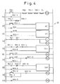
- the almost exhausted roving bobbins S which have completed the first step of the operation, are taken from the front and back bobbin hangers of the creel 19 by a pair of pegs 7, the axial distance therebetween can be expanded, and then these almost exhausted roving bobbins S are suspended by a pair of adjacent two empty bobbin hangers (indicated by X in Fig.
- the above-mentioned unit cycle operation for carrying out the roving bobbin exchange operation is carried out for the almost exhausted roving bobbins S suspended by the front and back bobbin hangers of the creel 19, which are located alternately along the creel 19, as mentioned above, from the gear end side to the outer end side of the spinning frame along the creel 19, and when the apparatus 4 arrives at the position facing the out end of the spinning frame SF, the apparatus actuates the second limit switch, that is the bobbin exchange confirmation switch LS2.
- the first limit switch that is the approach confirmation switch LS1 of the circuit (6) is not closed and the a-contact RY2-2 of the circuit (5) is kept open, and the reset signal is not input, and the timer TR1 becomes to time-up so that the time limiting contact TR1-1 of the circuit (1) is opened to de-energize the relay MS1 and stop the drive motor M1, and the spinning operation of the spinning frame SF is temporarily stopped. Accordingly, the roving bobbins having a smaller quantity of roving and supplying rovings to the above-mentioned spinning frame SF, do not reach a completely exhausted condition.
- the time limiting contact TR1-2 of the circuit 9 is closed.
- the approach confirmation switch LS1 of the circuit (6) is turned on to excite and self-retain the relay RY4 of the circuit (9), and the a-contact RY4-1 of the circuit (1) is closed to excite and self-retain the relay MS1.
- the driving motor M1 of the spinning frame SF is automatically started again and the supply of roving is restarted, and the apparatus 4 performs the bobbin exchange operation while spinning is continued, as mentioned above.
- the timer of the circuit (10) TR3 begins counting, and when the time count is completed in the timer TR3, the timer contact TR3-1 is opened after the lapse of a predetermined time from the time of re-starting.
- the time count is completed in the timer TR2 to open the time limiting contact TR2-1 of the circuit (1) and stop the spinning frame SF.
- full packaged roving bobbins F and medium size roving bobbins M are alternately suspended by the front row of bobbin hangers and the back row of bobbin hangers in a condition such that each front bobbins hanger and a back bobbin hanger facing thereto suspends roving bobbins having an identical roving winding size, and when the medium roving bobbins M become almost exhausted roving bobbins S, the roving bobbin exchange operation by the apparatus 4 is applied to these almost exhausted roving bobbins S.
- the present invention also can be applied to a process in which the bobbin exchange is conducted in succession, as disclosed in Japanese Unexamined Patent Publication No.
- the apparatus for controlling the operation of a spinning frame according to the present invention can be applied to a bobbin exchange system in which only the bobbin exchange is automatically carried out and the roving piecing operation is manually conducted.
- the roving of the almost exhausted roving bobbin S is cut in the vicinity of the roving guide, and the piecing operation is manually performed while this roving is moving to supply a draft part for this roving.
- the residual roving quantity indicating means and cop wound quantity indicating means can be constructed by a pulser which is connected to a back roller of the spinning frame SF and generates a pulse every time a predetermined length of the roving is fed by the rotation of the back roller, and a feed counter, which receives pulse signals from the pulser and integrates the quantity of fed roving or the quantity of fed roving corresponding to the quantity of yarn wound on the cop respectively.
- An automatic counter having a large preset number can be arranged as the time setting means instead of the timer.
- the sum of the quantity of produced yarn wound on the cop before the output of the bobbin exchange signal and the quantity of produced yarn wound on the cop during the above-mentioned allowable time is set as the wound quantity allowable for the approach of the roving bobbin exchange apparatus 4 in the automatic counter, and if a signal indicating the arrival of the apparatus 4 is not input before the above-mentioned allowable time is detected by the automatic counter, the drive motor is stopped.
- control circuit is illustrated as a circuit including relays and the like, but in the present invention, the control circuit can be constructed by a programmable controller now used frequently for electric control (provided with a microcomputer-equipped or internal timer-equipped device capable of programmably re-arranging a sequential control circuit). Furthermore, when the roving bobbin exchange apparatus 4 approaches the spinning frame SF after stopping of the spinning frame, the drive motor M1 can be manually restarted.
- a bobbin exchange signal is output when the roving quantity on a roving bobbin approaches a predetermined wound quantity for carrying out the bobbin exchange operation, another bobbin exchange signal is then output when the quantity of produced yarn wound on a cop becomes a quantity suitable for the bobbin exchange, a calling signal requesting the roving bobbin exchange apparatus 4 is output based on a logical product of both the signals and a drive motor of the spinning frame is stopped when the
- the bobbin exchange operation is performed when the quantity of residual roving of the roving bobbins, which will be subjected to the roving bobbin exchange operation, becomes the quantity for which the roving bobbin exchange is necessary, and the quantity of produced yarn wound on the cop becomes the quantity suitable for the bobbin exchange, the doffing operation of the spinning frame does not overlap the bobbin exchange operation. This is another advantage attained by the present invention.
Landscapes
- Engineering & Computer Science (AREA)
- Mechanical Engineering (AREA)
- Textile Engineering (AREA)
- Spinning Or Twisting Of Yarns (AREA)
Claims (6)
ein die Restvorgarnmenge anzeigendes Mittel (Schaltkreis (3)) zum Feststellen einer Menge des von den Vorgarnspulen gelieferten Vorgarns und zum Abgeben eines Vorgarnspulenaustauschsignals (erstes Signal), wenn sich die dadurch festgestellte Vorgarnmenge einer vorbestimmten gewickelten Menge nähert, die für den Vorgarnspulenaustauschvorgang geeignet ist,
ein Mittel (Schaltkreis (2)) zum Feststellen einer Menge von auf einen Kop gewickelten Garns und zum Abgeben eines Signals (zweites Signal), wenn die dadurch festgestellte Garnmenge einen Wert erreicht, der zur Durchführung des Vorgarnspulenaustauschvorgangs geeignet ist.
wobei die beiden Mittel auf jeder der Spinnmaschinen (SF) angeordnet sind,
einen Steuerkreis (Schaltkreis (4)) zum Abgeben eines Aufrufsignals zum Aufrufen der Vorgarnspulenaustauscheinrichtung (4) auf der Grundlage eines logischen produkts der ersten und zweiten Signale,
einen Annäherungsbestätigungsschalter (LS1) zum Bestätigen einer Ankunft der auf einem äußeren Endrahmen einer Spinnmaschine (SF) angeordneten Vorgarnspulenaustauschvorrichtung (4), welcher ein drittes Signal abgeben kann, welches die Ankunft der Vorgarnspulenaustauscheinrichtung (4) bestätigt,
ein Vorgabezeit-Einstellmittel (Schaltkreis (5)), welches betätigt werden kann, wenn das Aufrufsignal von der Spinnmaschine abgegeben wird, um eine Vorgabezeit vom Zeitpunkt der Abgabe des Aufrufsignals zu einer Zeitbegrenzung einzustellen, zu der die Vorgarnspulenaustauscheinrichtung (4) angekommen sein sollte,
wobei der Annäherungsbestätigungsschalter (LS1) und das Vorgabezeit-Einstellmittel (Schaltkreis (5)) so angeordnet sind, daß sie mit dem Steuerkreis zusammenarbeiten,
wobei der Steuerkreis (20) weiter mit elektrischen Mitteln (Schaltkreis (1)) zum Starten und Stoppen eines Antriebs der Spinnmaschinen (SF) und zum Zusammenarbeiten mit dem Annäherungsbestätigungsschalters (LS1) und dem Vorgabezeit-Einstellmittel (Schaltkreis (5)) versehen ist,
wobei, wenn das dritte Signal nicht innerhalb der von dem Vorgabezeit-Einstellmittel eingestellten Vorgabezeit nach Abgabe des Aufrufsignals in dem Steuerkreis (Schaltkreis (4)) abgegeben wird, die elektrischen Mittel (Schaltkreis (1)) zum Stoppen und Starten eines Antriebs der Spinnmaschine den Antrieb der Spinnmaschine stoppt.
einem Zeitgeber (TR2), welcher eine Vorgabezeit zum Abschluß des Vorgarnspulenaustauschvorgangs für die Spinnmaschine von einem Zeitpunkt, zu dem das dritte Signal abgegeben wird, einstellt,
einem Stromkreis (Schaltkreis (8)) zum Einstellen der Vorgabezeit für das Abschließenm des Vorgarnspulenaustauschvorgangs, wobei dieser mit dem Zeitgeber (TR2) kombiniert ist,
Mitteln (Schaltkreis (7)) zum Abgeben eines Signals (viertes Signal), welches den Abschluß des Vorgarnspulenaustauschvorgangs anzeigt,
wobei jede der Spinnmaschinen (SF) mit dem Stromkreis und den Signalabgabemitteln versehen ist,
wobei, wenn das vierte Signal nicht innerhalb der Vorgabezeit zum Abschluß des Vorgarnspulenaustauschvorgangs abgegeben wird, die elektrischen Mittel zum Starten und Stoppen eines Antriebs der Spinnmaschine betätigt werden, um einen Antrieb der Spinnmaschine zu stoppen.
Applications Claiming Priority (2)
| Application Number | Priority Date | Filing Date | Title |
|---|---|---|---|
| JP62312941A JPH07122177B2 (ja) | 1987-12-10 | 1987-12-10 | 篠交換システムにおける精紡機の運転制御装置 |
| JP312941/87 | 1987-12-10 |
Publications (2)
| Publication Number | Publication Date |
|---|---|
| EP0321404A1 EP0321404A1 (de) | 1989-06-21 |
| EP0321404B1 true EP0321404B1 (de) | 1992-03-18 |
Family
ID=18035318
Family Applications (1)
| Application Number | Title | Priority Date | Filing Date |
|---|---|---|---|
| EP88810846A Expired EP0321404B1 (de) | 1987-12-10 | 1988-12-08 | Vorrichtung zur Steuerung und Regelung der Arbeitsweise einer Spinnmaschine bei einem System zum Austausch von Vorlagespulen |
Country Status (4)
| Country | Link |
|---|---|
| US (1) | US4890452A (de) |
| EP (1) | EP0321404B1 (de) |
| JP (1) | JPH07122177B2 (de) |
| DE (1) | DE3869362D1 (de) |
Cited By (1)
| Publication number | Priority date | Publication date | Assignee | Title |
|---|---|---|---|---|
| EP3763858A1 (de) | 2019-07-11 | 2021-01-13 | Saurer Spinning Solutions GmbH & Co. KG | Vorgarnspulengatter für eine ringspinnmaschine |
Families Citing this family (7)
| Publication number | Priority date | Publication date | Assignee | Title |
|---|---|---|---|---|
| DE3900507A1 (de) * | 1989-01-10 | 1990-07-12 | Rieter Ag Maschf | Verfahren und vorrichtung zur durchfuehrung eines blockwechsels bei einer ringspinnmaschine |
| JP3042000B2 (ja) * | 1991-03-11 | 2000-05-15 | 豊和工業株式会社 | 粗紡機の適位置停止装置 |
| US5463557A (en) * | 1992-05-15 | 1995-10-31 | Kabushiki Kaisha Toyoda Jidoshokki Seisakusho | Roving machine |
| CN102586967A (zh) * | 2012-01-22 | 2012-07-18 | 经纬纺织机械股份有限公司 | 新型细纱筒管锭衬 |
| CN106995955A (zh) * | 2017-04-10 | 2017-08-01 | 中国地质大学(武汉) | 一种带视觉的自动落纱机 |
| WO2019104574A1 (zh) * | 2017-11-30 | 2019-06-06 | 苏州欧博时装有限公司 | 一种用于纺纱机的纱筒传输存储设备 |
| CN115467061B (zh) * | 2022-10-26 | 2024-05-24 | 常州市同和纺织机械制造有限公司 | 一种自动落纱握纱横梁的检测装置及其检测方法 |
Family Cites Families (9)
| Publication number | Priority date | Publication date | Assignee | Title |
|---|---|---|---|---|
| GB1419905A (en) * | 1974-02-02 | 1975-12-31 | Howa Machinery Ltd | Bobbin doffing and onning apparatus |
| US4145868A (en) * | 1978-02-17 | 1979-03-27 | Howa Kogyo Kabushiki Kaisha | Mobile type auto-doffer provided with doffing device and donning device for ring spinning machine and the like |
| JPS5969367A (ja) * | 1982-10-06 | 1984-04-19 | Toyoda Autom Loom Works Ltd | 自動機の走行異常検出方法 |
| EP0213962B1 (de) * | 1985-09-04 | 1991-09-04 | Howa Machinery Limited | Verfahren und Vorrichtung zum Verbinden von Vorgarn in Spinnmaschinen |
| JPS6262929A (ja) * | 1985-09-11 | 1987-03-19 | Howa Mach Ltd | 精紡クリ−ルの篠交換指令装置 |
| JPH0655973B2 (ja) * | 1986-05-23 | 1994-07-27 | 豊和工業株式会社 | 紡機における作業機 |
| JP2553052B2 (ja) * | 1986-08-25 | 1996-11-13 | 豊和工業株式会社 | 精紡機における篠換方法 |
| JPH06253425A (ja) * | 1993-03-02 | 1994-09-09 | Fuji Electric Co Ltd | 引出形遮断器の引出機構 |
| JP3284651B2 (ja) * | 1993-03-10 | 2002-05-20 | 株式会社デンソー | 車両用空気調和装置 |
-
1987
- 1987-12-10 JP JP62312941A patent/JPH07122177B2/ja not_active Expired - Lifetime
-
1988
- 1988-12-06 US US07/280,580 patent/US4890452A/en not_active Expired - Fee Related
- 1988-12-08 DE DE8888810846T patent/DE3869362D1/de not_active Expired - Fee Related
- 1988-12-08 EP EP88810846A patent/EP0321404B1/de not_active Expired
Cited By (2)
| Publication number | Priority date | Publication date | Assignee | Title |
|---|---|---|---|---|
| EP3763858A1 (de) | 2019-07-11 | 2021-01-13 | Saurer Spinning Solutions GmbH & Co. KG | Vorgarnspulengatter für eine ringspinnmaschine |
| DE102019118781A1 (de) * | 2019-07-11 | 2021-01-14 | Saurer Spinning Solutions Gmbh & Co. Kg | Vorgarnspulengatter für eine Ringspinnmaschine |
Also Published As
| Publication number | Publication date |
|---|---|
| JPH07122177B2 (ja) | 1995-12-25 |
| EP0321404A1 (de) | 1989-06-21 |
| JPH01156527A (ja) | 1989-06-20 |
| US4890452A (en) | 1990-01-02 |
| DE3869362D1 (de) | 1992-04-23 |
Similar Documents
| Publication | Publication Date | Title |
|---|---|---|
| US5517404A (en) | Process control in the textile plant | |
| US3884026A (en) | Method and apparatus for effecting replacement of cans in spinning frame | |
| US3486319A (en) | Apparatus and method for detecting,piecing-up and reporting ends down on spinning machines | |
| EP0321404B1 (de) | Vorrichtung zur Steuerung und Regelung der Arbeitsweise einer Spinnmaschine bei einem System zum Austausch von Vorlagespulen | |
| EP3628761B1 (de) | Verfahren zum betrieb einer ringspinnmaschine | |
| US4156341A (en) | Apparatus for monitoring sliver feed in a spinning machine | |
| US3906712A (en) | Method and apparatus for transferring yarn packages from a textile machine to a carrying device | |
| JP2845980B2 (ja) | 自動紡績機の紡糸部にスライバを供給する方法と装置 | |
| US4821504A (en) | System for controlling displacement of carriage working machines | |
| JPS63225076A (ja) | 自動ワインダ−におけるロツトチエンジ方法 | |
| JPH0217464B2 (de) | ||
| JP2895192B2 (ja) | 糸を繊維機械の巻成部へ引渡すための方法と装置 | |
| US4771597A (en) | Method and apparatus for automatically exchanging roving bobbins | |
| US4582270A (en) | Method of transferring yarn packages in a spinning frame | |
| US4563873A (en) | Apparatus for controlling production in a spinning machine | |
| US4541577A (en) | Method of transferring yarn packages in a spinning frame | |
| EP0296298B1 (de) | System zur Steuerung der Fahrbewegung einer wagenartigen Bedienungsvorrichtung | |
| US5987868A (en) | Monitoring of core mounting for a roving frame | |
| US2463028A (en) | Doffing indicator system | |
| CN223620568U (zh) | 一种环锭细纱机用高速理落管装置 | |
| JP2580688B2 (ja) | 精紡機の篠替管理方法 | |
| JP3075137B2 (ja) | 精紡機におけるトレイ移送装置の運転制御方法及び運転制御装置 | |
| JP2546359B2 (ja) | 紡機の管替方法 | |
| CN116891162A (zh) | 用于操作经由筒和管传输系统连接到环锭纺纱机的交叉卷绕机的方法和装置 | |
| JPH0734941Y2 (ja) | 精紡機における工程歩進待ち状態表示装置 |
Legal Events
| Date | Code | Title | Description |
|---|---|---|---|
| PUAI | Public reference made under article 153(3) epc to a published international application that has entered the european phase |
Free format text: ORIGINAL CODE: 0009012 |
|
| 17P | Request for examination filed |
Effective date: 19881217 |
|
| AK | Designated contracting states |
Kind code of ref document: A1 Designated state(s): CH DE IT LI |
|
| 17Q | First examination report despatched |
Effective date: 19901114 |
|
| GRAA | (expected) grant |
Free format text: ORIGINAL CODE: 0009210 |
|
| AK | Designated contracting states |
Kind code of ref document: B1 Designated state(s): CH DE IT LI |
|
| ITF | It: translation for a ep patent filed | ||
| REF | Corresponds to: |
Ref document number: 3869362 Country of ref document: DE Date of ref document: 19920423 |
|
| PLBE | No opposition filed within time limit |
Free format text: ORIGINAL CODE: 0009261 |
|
| STAA | Information on the status of an ep patent application or granted ep patent |
Free format text: STATUS: NO OPPOSITION FILED WITHIN TIME LIMIT |
|
| 26N | No opposition filed | ||
| PGFP | Annual fee paid to national office [announced via postgrant information from national office to epo] |
Ref country code: DE Payment date: 19961220 Year of fee payment: 9 |
|
| PGFP | Annual fee paid to national office [announced via postgrant information from national office to epo] |
Ref country code: CH Payment date: 19961230 Year of fee payment: 9 |
|
| PG25 | Lapsed in a contracting state [announced via postgrant information from national office to epo] |
Ref country code: LI Free format text: LAPSE BECAUSE OF NON-PAYMENT OF DUE FEES Effective date: 19971231 Ref country code: CH Free format text: LAPSE BECAUSE OF NON-PAYMENT OF DUE FEES Effective date: 19971231 |
|
| REG | Reference to a national code |
Ref country code: CH Ref legal event code: PL |
|
| PG25 | Lapsed in a contracting state [announced via postgrant information from national office to epo] |
Ref country code: DE Free format text: LAPSE BECAUSE OF NON-PAYMENT OF DUE FEES Effective date: 19980901 |
|
| PG25 | Lapsed in a contracting state [announced via postgrant information from national office to epo] |
Ref country code: IT Free format text: LAPSE BECAUSE OF NON-PAYMENT OF DUE FEES;WARNING: LAPSES OF ITALIAN PATENTS WITH EFFECTIVE DATE BEFORE 2007 MAY HAVE OCCURRED AT ANY TIME BEFORE 2007. THE CORRECT EFFECTIVE DATE MAY BE DIFFERENT FROM THE ONE RECORDED. Effective date: 20051208 |