EP0318364A1 - Panzerschrank - Google Patents
Panzerschrank Download PDFInfo
- Publication number
- EP0318364A1 EP0318364A1 EP88402912A EP88402912A EP0318364A1 EP 0318364 A1 EP0318364 A1 EP 0318364A1 EP 88402912 A EP88402912 A EP 88402912A EP 88402912 A EP88402912 A EP 88402912A EP 0318364 A1 EP0318364 A1 EP 0318364A1
- Authority
- EP
- European Patent Office
- Prior art keywords
- safe
- face
- rod
- plate
- support
- Prior art date
- Legal status (The legal status is an assumption and is not a legal conclusion. Google has not performed a legal analysis and makes no representation as to the accuracy of the status listed.)
- Withdrawn
Links
Images


Classifications
-
- B—PERFORMING OPERATIONS; TRANSPORTING
- B60—VEHICLES IN GENERAL
- B60R—VEHICLES, VEHICLE FITTINGS, OR VEHICLE PARTS, NOT OTHERWISE PROVIDED FOR
- B60R7/00—Stowing or holding appliances inside vehicle primarily intended for personal property smaller than suit-cases, e.g. travelling articles, or maps
- B60R7/08—Disposition of racks, clips, holders, containers or the like for supporting specific articles
- B60R7/087—Disposition of racks, clips, holders, containers or the like for supporting specific articles for stowing money or valuables, e.g. using safes
-
- B—PERFORMING OPERATIONS; TRANSPORTING
- B60—VEHICLES IN GENERAL
- B60P—VEHICLES ADAPTED FOR LOAD TRANSPORTATION OR TO TRANSPORT, TO CARRY, OR TO COMPRISE SPECIAL LOADS OR OBJECTS
- B60P3/00—Vehicles adapted to transport, to carry or to comprise special loads or objects
- B60P3/03—Vehicles adapted to transport, to carry or to comprise special loads or objects for transporting money or other valuables
-
- E—FIXED CONSTRUCTIONS
- E05—LOCKS; KEYS; WINDOW OR DOOR FITTINGS; SAFES
- E05G—SAFES OR STRONG-ROOMS FOR VALUABLES; BANK PROTECTION DEVICES; SAFETY TRANSACTION PARTITIONS
- E05G1/00—Safes or strong-rooms for valuables
- E05G1/005—Portable strong boxes, e.g. which may be fixed to a wall or the like
Definitions
- the invention intends to remedy this state of affairs, by providing to embark in the vehicle a safe. It is, of course, to be avoided that this safe can be detached from the vehicle structure easily and against the will of its owner.
- the destination of the majority of vehicles is also not to transport a safe and it is therefore important to have the possibility of moving the safe inside the enclosure in which it is arranged, in retaining its inviolability, so as to make the presence of the safe as inconvenient as possible vis-à-vis the normal use of the vehicle.
- the safe in the case where the safe is contained inside the luggage compartment of a passenger vehicle, efforts must be made, while leaving the safe attached to the structure of this vehicle, to him allow to occupy several non-annoying places with regard to the loading of luggage.
- GB-A-2 105 399 shows the installation of a safe in a vehicle, a conventional installation, the safe being permanently fixed in one position inside the vehicle.
- US-A-4,457,240 describes a resistant box transportable by its owner, but, apparently, can only be fixed to the structure of a vehicle in one location. Again, the problem of discomfort that can cause the presence of such an object in an enclosure initially intended for another use has not been seen, and no solution has been proposed to minimize it. In addition, the very shape of the box shown does not make it particularly practical for the safe transport of precious objects such as, for example, small suitcases or briefcases. documents likely to contain precious objects or documents.
- the invention has succeeded in defining the concept of a set of safes usable in vehicles, intended to be placed in the luggage compartment, or elsewhere, depending on its size, but also usable in non-mobile dwellings, as well as in mobile vehicles, other than motor vehicles, such as public works vehicles, planes or small tonnage boats.
- the subject of the invention is therefore a set of a generally rectangular external safe defined by a width, a height and a depth, one of the dimensions - height and width - being considerably less than the depth, this set being mounted on a fixing structure.
- the safe is mounted on the structure by means of at least a first pivot axis permanently oriented in a direction substantially parallel to a face of the safe defined by said height and width and substantially orthogonal to that of these two dimensions which is significantly less than the depth, said first pivot axis being also inaccessible from the external environment of the safe, so that, relative to said structure, this safe is likely to occupy a first position in which the depth is not parallel to a first reference plane (being perpendicular or oblique with respect to said first reference plane), the discomfort caused by the size of the safe is significant, and, a second position , which is deduced from said first position by pivoting of the safe around the first pivot axis and in which the depth extends parallel to said premi er reference plane, the discomfort caused by the size of the safe then being considerably reduced compared to that mentioned above corresponding to the first position of the safe.
- a second pivot axis substantially orthogonal to said first pivot axis and inaccessible from the external environment of the safe performs the pivoting mounting of the safe relative to a support which is pivotally mounted relative to the structure around said first pivot axis, so that, relative to said structure, the safe is capable of occupying a third position which is deduced from the second position at least by a pivoting of the trunk strong around the second pivot axis and in which, on the one hand, the depth extends parallel to a second reference plane, on the other hand, the discomfort caused by the size of the safe is considerably reduced by compared to that corresponding to said first position of the safe;
- the first pivot axis is mounted on a support which is itself pivotally mounted relative to the structure around a second pivot axis substantially orthogonal to said first pivot axis and inaccessible from the external environment of the safe, so that, relative to said structure, the safe
- the structure comprises a wall delimited by an upper face and by a lower face accessible to a safe fitter
- the device for mounting the safe being constituted by: - two rods, which cross said wall, being placed on either side of the safe and extending substantially perpendicular to the wall, each of these rods having a first end constituting the support of a support plate and having the second mini end of a thread; - two nuts, which cooperate with said threads so as to support said bearing plates on one face of the wall and thus to fix said rods to the wall, and - two screws, which each cooperate with a tapped hole in each nut, substantially orthogonally to the axis of the corresponding rod, which each pass through a hole in two opposite walls of the safe and whose heads (screws ) are contained inside the safe and are only accessible from the inside of this safe.
- At least one of the rods has its upper end which extends upwards beyond the corresponding nut, while the device for selective retention of the safe in its second position is fixed on the upper end of said rod and is constituted by at least one latch, which is pivotally mounted on a screwed support and immobilized on the upper end of said rod and on which the face of the safe, by which it rests on the seat when it is placed in its first position, is likely to be in abutment in order to limit the pivoting of the safe when the latter is then placed in its second position.
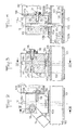
- Figure 1 schematically shows the interior of the luggage compartment of a passenger vehicle bounded by the rear bottom 101, substantially vertical, the floor 102, substantially horizontal, a left vertical side wall 103, a right vertical side opening 104, giving access to the housing 105 of a spare wheel 106, and, a horizontal upper wall 107.
- a safe 108 of parallelepipedal shape, capable of containing, for example, a leather or similar briefcase or a small suitcase, document holder, is arranged inside this luggage compartment. It is a safe, the installation of which will be described below with reference to FIGS. 5A, 5B 6A, 6B, 7A and 7B, the three dimensions of which are the depth P, perpendicular to the access door.
- a parallelepipedic support 110 is pivotally mounted on the floor structure 102 around a vertical geometric axis 111, and carries a pivoting axis around a horizontal geometric axis 112, which is perpendicular to the face 113 of the safe opposite to the door 109, the safe being pivotally mounted relative to the support 110 around the geometric axis 112.
- a rectangular tongue 114 is pivotally mounted on the support 110 around a geometric axis 115 orthogonal to the two other geometric axes 111 and 112, this tongue 114 being held horizontally by resting on the upper face of a projection 116 which is provided with the front face of the support 110, and thus being arranged opposite one (117) of the large sides of the safe, keeping it in the upright position, near the bottom 101 of the luggage compartment, the width L being perpendicular to this bottom 101, and the depth P and the height H being parallel to the bottom 101.
- the support 110 and its mounting have the following particularities: -
- the support 110 includes a threaded bore 118 of vertical geometric axis 111;
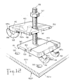
- a threaded rod 119 capable of being screwed into the threaded bore 118, is erected vertically from the upper face 120 of a plate 121 on which its end lower 122 is welded, said plate 121 being further provided with two vertical pins 123 also welded on its upper face 120;
- the floor 102 is constituted by a composite structure of two horizontal sheets kept apart by connecting webs, comprising a through hole 124 and two lower blind holes 125, the rod 119 passing through the hole 124, as well as a support plate 126 disposed in abutment on the upper face 102 a of the floor 102, and the pins 123 passing through the holes 125, a nut 127, screwed onto the threaded rod 119, making it possible to subject the latter to the floor 102 by supporting the upper face 120 of the plate 121 on the lower face
- the device of Figures 2, 3 and 4 can receive several applications.
- the face of the safe is the side that the user has, at least partially, in front of him when he wishes to put an object in the safe or remove it; it is the rib which is provided with the door 109 of the safe.
- the safe is pivotally mounted relative to the support 110 by means of the screw 130-131 which is introduced inside the safe, and the threaded part 130 of which passes through the hole 133 provided in the lower front part of the trunk wall defined externally by the face 113.
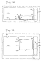
- the door 109 In its position represented by FIGS. 1 and 6A, 6B, the door 109 is parallel to the plane of the opening 104 of the housing 105 of the spare wheel 106.
- the safe is stored along the vertical bottom 101 of the compartment to baggage and its longitudinal dimensions, corresponding to the width L, is small. On the other hand, it is difficult, if not impossible, to open door 109 and to put an object in the trunk or to remove it.
- the tongue 114 on which the front face 117 of the safe abuts, keeps the latter with this front face 117 vertical, preventing the safe from pivoting about the axis 112.
- the user To be able to open the door 109 and have access to the interior of the safe, the user, starting from the position of FIGS. 6A, 6B, pivots the support 110 (and, consequently, also the safe 108 ) around the vertical axis 111, to the new position in FIGS. 5A, 5B.
- the safe 108 occupies an important place in the longitudinal direction of the luggage compartment, but the door 109 can be opened, and unmask opening 137 of the trunk. In this position, it is easy to place an object inside the safe or remove it.
- the tongue 114 here too, prevents an unwanted tilting of the trunk around the horizontal axis 112.
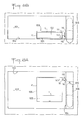
- the user wishes to be able to use the full length of the luggage compartment, even if he does not have at his disposal q a lower useful height. He can then, starting from the position of FIGS. 6A, 6B, tilt the tongue 114 to release the pivoting of the safe 108 around the horizontal axis 112.
- the safe is placed in the position Figures 7A, 7B, with its width which extends vertically ( Figure 7B), over a relatively small distance, freeing above the safe the entire length of the luggage compartment.
- the large faces of the safe are then substantially parallel to the floor 102, and suitcases, even longitudinally bulky, can be placed above the safe 108.
- the large dimension (the depth P) has been arranged parallel to the bottom 101 of the luggage compartment, the smallest dimension (the width L) extending perpendicular to said bottom 101, so that, in this direction, the size of the safe is minimal.
- FIG. 8A, 8B, 9A, 10A, 10B and 11A, 11B Another application of the device of Figures 2, 3 and 4 is shown in Figures 8A, 8B, 9A, 10A, 10B and 11A, 11B.
- the safe is first shown ( Figures 8A, 8B) in the position where a user has access to the interior 132, the door 109 being open.
- the width L constitutes the largest dimension
- the height H the smallest dimension
- the depth P the intermediate dimension.
- Door 109 leaves the face open vertical front to insert objects into the safe.
- the width L and the depth P are parallel to the floor 102 and the height H extends vertically.
- the size of the floor 102 of the luggage compartment is large.
- the safe is pivotally mounted, relative to the support 110, about the horizontal axis 112 by means of a non-visible screw, which is introduced into the tapped hole 129, shown in FIG. 4.
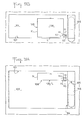
- the user of the arrangement of FIGS. 8A, 8B can then, after having closed the door 109 of the safe 108, vertically straighten the safe, by pivoting it around the horizontal axis 112, until reaching the position of FIGS. 9A, 9B.
- the depth P and the height H are parallel to the bottom 101 of the luggage compartment and the smallest dimension, the height H is horizontal, perpendicular to said bottom 101: the size of the floor 102 has been considerably reduced (FIG. 9A), and, to maintain the large faces of the safe, delimited by the depth P and the width L, vertical, the tongue 114 is placed in front, which becomes the visible front face 138 of the safe 108.
- the user may, moreover, wish not to lose anything in the longitudinal direction of the dimension (of the depth) of the luggage compartment, and prefer to accept a slight reduction in the space available in the direction of the width of the luggage compartment. It suffices in this case to place the safe along the opening 104 of the spare wheel housing 106 ( Figures 10A, 10B). To do this, starting from the position shown in Figures 9A, 9B, it rotates about 90 °, around the vertical axis 111, the safe 108, whose depth P and width L are parallel in the plane of the opening 104, the width L extending horizontally, the depth P extending vertically. The smallest dimension, the height H of the safe, extends perpendicular to the plane of the opening 104. The safe therefore takes up little space across the width of the luggage compartment, and has space in particular the place he occupied, longitudinally, in the position shown in Figures 9A, 9B.
- the safe 108 can, from the position shown in FIGS. 10A, 10B, be slightly tilted inside the housing 105 of the spare wheel 106 into which its upper part penetrates through the opening 104, until it comes to bear on the spare wheel. It is the position of FIGS. 11A, 11B which is deduced from those of FIGS. 10A, 10B by pivoting of the safe 108 around the horizontal axis 112.
- the fixing of the safe is impossible to dismantle by someone who does not have the key to the door of the safe and who therefore does not have access to the interior of the safe 108.
- the inner plate 121 being pressed on the underside 102 b , the pins 123 are inaccessible and cannot be sawn, which would make it possible to unscrew the plate 121 relative to the support 110.
- the threaded rod 119 cannot either be sawed at the level of the plate 126, the clearance J not allowing the passage of a saw blade.
- the nut 127 cannot be unscrewed, since, after screwing the support 110 on the threaded rod 119, this nut 127 is hidden inside the recess 128.
- the safe 108 cannot be detached from the support 110 only by the one who can remove the screw 130-131, that is to say by the owner of the safe, who has the key, thus has access to the interior 132 of the safe and can reach the screw head 131.
- the threaded rod 119 initially has a height greater than the sum of the assembled parts, so that an excess 119 a of this threaded rod protrudes from the upper face of the support 110. When mounting, it suffices cut the threaded rod to remove this excess 119 a .
- mounting can be ensured on all vehicles, regardless of the thickness of their floor 102.
- the means of making the rod 119 of the floor 102 integral which has been described with reference to FIGS. 2, 3 and 4, assumes the possibility for the user to drill through the floor 102, in particular having access to its face. lower 102 b . This possibility does not always exist, at least with ease, in particular because of the location of the fuel tank below the floor, in the zone, where it would be necessary to install the plate 121.
- the floor 102 comprises two sheets spaced apart from each other, an inner sheet 102 e an upper sheet 102 d , itself delimited by a first lower face 102 f and a second upper face 102 h .
- a first plate 139 itself comprises a first upper face 140 and a second lower face 141 and and provided with two first hooks 142 which are integral therewith, fixed on the second face 141, and are bent towards the plane 143 of this second face 141, being removed from it.
- the rod 119 is erected substantially perpendicularly from the first face 140.
- the upper plate 102 of the floor is crossed by two first holes 144, which are arranged to allow passage of the free ends 142 has hooks 142.
- a second plate 145 has a lower face 146 and a notch 147 for passage of the rod 119.
- Two second hooks 148 are integral with the second plate 145, are fixed on its lower face 146 and are bent towards the plane 149 of this lower face 146, being removed from it.
- the upper sheet 102d of the floor is crossed by two second holes 150, which are arranged so as to allow the passage of free ends 148 has hooks 148.
- the first plate 139 has an extra thickness 151 which corresponds to the thickness of a thinned part 152 of the second plate.
- the ends 142 a of the first hooks 142 are introduced into the holes 144 until the second face 141 of the first plate rests on the second face 102 h of the sheet 102 d and that then, the ends 142 has hooks 142 are in contact with the first face 102 f of the sheet 102 d ( Figure 13). Then, the ends 148 a of hooks 148 are in their turn introduced into the second holes 150, until the lower face 146 of the second plate 145 rests on the second face 102 h of the sheet 102 d , and that then, the ends 148 a of hooks 148 are in contact with the first face 102 f of the sheet 102 d (FIG. 14).
- the rod 119 has had the possibility of entering the notch 147; the lower face 152 a of the thinned part 152 of the second plate 145 rests on the first face 140 of the first plate 139; finally, the nut 127 is completely screwed and presses on the upper face 153 of the second plate 145 and thus assembles the first (139) and second (145) plates, the first hooks 142 and the second hooks 148 preventing the separation of the 'these two plates together with the sheet 102 d .
- the rod 119 is fixed on the floor 102, and then allows the mounting of the support 110 already described with reference to FIGS. 2 to 4.
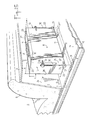
- FIGS. 15 to 18 Another alternative embodiment is shown with reference to FIGS. 15 to 18, which therefore represent a safe in accordance with the invention, installed in the luggage compartment of a passenger car.
- This safe has dimensions that allow, for example, to house a travel case containing documents of great value.
- the vehicle is shown in part and there are distinguished: 1 the upper face of the horizontal base 1 of the luggage compartment, consisting of a steel sheet; the face 2 has the vertical wall (substantially vertical) 2, defining the bottom front of the luggage compartment, and extended at its upper part by a horizontal shelf 3.
- the wall 2 and the board 3 define the passenger compartment 4: the folder 5 of the rear seat of the vehicle is against the wall 2.
- a radiant 6, forming a spar, is fixed on the lower face 1 b of the sheet 1.
- the wall 2 intersects the seat 1 along an edge 7, parallel to the direction D of the width of the vehicle.
- the luggage compartment contains a safe consisting of the following six external faces, two to two parallel, defined with respect to a first position of this safe, shown in broken lines in Figure 18: the underside 8, substantially horizontal; the upper face 9, parallel and opposite to the face 8; the rear face 10, substantially vertical and substantially parallel to the wall 2 of the passenger compartment; the front face 11, parallel and opposite to the face 10 and constituting the door of the safe, pivotally mounted about a horizontal geometric axis 15, located at the bottom of the face 11; the vertical face 12, which delimits the left side wall 14; and the opposite vertical face 13, which delimits the right side wall of the safe.
- the faces 8 and 11, 8 and 10, 9 and 11, and 9 and 10 have in common, respectively, the edges 16, 17, 18 and 19, which define the width L of the safe and which are parallel to the edge 7 of the luggage compartment; the faces 10 and 12, 10 and 13, 11 and 12, and 11 and 13 have in common, respectively, the edges 20, 21, 22 and 23, which define the height H of the safe; finally, the faces 8 and 12, 8 and 13, 9 and 12, and, 9 and 13 have in common, respectively, the edges 24, 25, 26 and 27, which define the depth P of the safe.
- the face 8 delimits the wall 28, while the face 10 delimits the wall 29 of the safe.
- Two rods 30 are erected vertically along the lateral vertical faces 12 and 13 of the safe, on either side of this safe, are provided at their lower ends with support plates 31, of steel, which there are welded, have their upper parts provided with a thread 32 and pass through holes 33 made in the stiffeners 6 and in the seat 1, being introduced from below the luggage compartment until the support plates 31 come to bear on the lower face 6 has stiffeners 6.
- Nuts 34 produced in thick cylindrical washers, cooperating with the threads 32 of the rods 30 and permanently fix these rods on the seat 1, being oriented so that the flat faces of the washers constituting them are parallel to the lateral vertical faces 12 and 13 of the safe, these washers being spaced apart just enough to allow the introduction of the safe between them, said vertical faces 12 and 14 being di facing and adjacent to said washers.
- the wall 14 of the safe, and the opposite parallel wall, are drilled at their rear and lower parts (when the safe is placed flat on the seat, as shown in broken lines in Figure 18) a hole 35.
- a threaded hole 36 is provided, opposite which a hole 35 can be arranged.
- Two screws (only one visible) 37 are introduced into the safe, while the door 11 is open, each pass through a hole 35 and are each screwed into a tapped hole 36 until, on the one hand, each screw 37 is screwed completely into the tapped hole 36, and then, on the other hand, the safe pivots freely around the common geometric axis 38 of the screws 37, the heads 37 has screws 37 forming displacement stops for the interior faces of two vertical side walls of the safe.
- the axis 38 is orthogonal to the axis of each rod 30, but does not cut this axis of each rod 30.
- each support 39 carries a tilting latch 41, which has its tilting limited by a lug 42, the latch being so horizontal and capable, as shown in FIGS. 15 and 17, of keeping the safe vertically, by forming stops on the face 8 of this safe.
- adjustable stops 43 are screwed onto the rear wall 44 of the safe (the one which supports the face 10) and make it possible to maintain the safe with its vertical faces 8 and 9, in the second position that this safe can occupy .
- the face 9 is arranged opposite and close to the face 2 a of the wall 2 and the size of the safe is reduced, taking into account the fact that its height H is notably less than its depth P , and that, in this second position, the height H extends horizontally and the depth P extends vertically inside the luggage compartment.
- the rest of this luggage compartment is still important for the storage of the luggage itself.
- the safe can be kept in its second position thanks to the latches 41, and can very easily be returned to its first position (broken lines in FIG. 18) so that the user has access to its interior storage volume, by tilting. about 90 ° around the geometric axis 38.
- the tilting mounting of the safe around the axis 38 which has been provided, effectively ensures that the safe does not move out of the luggage compartment, since the nuts 34 and the parts of the rods 30 to which they have been screwed , like the screws 37 themselves, are indestructible quickly and cannot be dismantled when the door 11 of the safe is closed. Indeed, the mounting of the screws 37 is carried out when this door 11 is open, disassembly being impossible after closing the gate 11, that is to say while the safe houses its precious load.
- Such a safe can also be mounted, with the same device as that which has been described, inside the passenger compartment of the vehicle, for example near the front faces of the front seats, or in a mobile machine such as '' a mobile crane or shovel, or in a home, behind a chair, for example.
Landscapes
- Engineering & Computer Science (AREA)
- Mechanical Engineering (AREA)
- Health & Medical Sciences (AREA)
- Public Health (AREA)
- Transportation (AREA)
- Pivots And Pivotal Connections (AREA)
- Body Structure For Vehicles (AREA)
- Fittings On The Vehicle Exterior For Carrying Loads, And Devices For Holding Or Mounting Articles (AREA)
Applications Claiming Priority (2)
| Application Number | Priority Date | Filing Date | Title |
|---|---|---|---|
| EP87402650 | 1987-11-24 | ||
| EP87402650 | 1987-11-24 |
Publications (1)
| Publication Number | Publication Date |
|---|---|
| EP0318364A1 true EP0318364A1 (de) | 1989-05-31 |
Family
ID=8198276
Family Applications (1)
| Application Number | Title | Priority Date | Filing Date |
|---|---|---|---|
| EP88402912A Withdrawn EP0318364A1 (de) | 1987-11-24 | 1988-11-21 | Panzerschrank |
Country Status (3)
| Country | Link |
|---|---|
| US (1) | US5031548A (de) |
| EP (1) | EP0318364A1 (de) |
| JP (1) | JPH01244936A (de) |
Families Citing this family (9)
| Publication number | Priority date | Publication date | Assignee | Title |
|---|---|---|---|---|
| GB2284187A (en) * | 1993-11-29 | 1995-05-31 | Keith Clifford Boast | Car Radio Safe |
| US5513580A (en) * | 1994-02-28 | 1996-05-07 | Franks; Curtis | Lockbox for installation in closets |
| GB2311050B (en) * | 1996-03-15 | 2000-07-12 | Kevin Vincenzo Keating | A safe system for vehicles |
| GB2318333B (en) * | 1996-10-07 | 2001-02-21 | Alan James Shone | Anti-theft vehicle safe box |
| US6712415B1 (en) * | 2000-04-05 | 2004-03-30 | Durakon Acquisition Corp. | Easy to install pull out cargo-carrying tray frame for pickup trucks |
| US20080196637A1 (en) * | 2007-02-21 | 2008-08-21 | Harry Michael Howell | Interactive safe for vehicles |
| WO2009052388A2 (en) * | 2007-10-17 | 2009-04-23 | Kim Sherman | Removable safe for a vehicle |
| US8456819B1 (en) | 2009-03-30 | 2013-06-04 | Brian Delynn Smith | Personal storage device with charging capability |
| US20190176675A1 (en) * | 2017-12-13 | 2019-06-13 | Ford Global Technologies, Llc | Motor vehicle equipped with a strongbox and method for securing a valuable item in a motor vehicle |
Citations (3)
| Publication number | Priority date | Publication date | Assignee | Title |
|---|---|---|---|---|
| GB2105399A (en) * | 1981-07-04 | 1983-03-23 | Woodward Roger Clive | Security box or cabinet |
| US4457240A (en) * | 1982-06-25 | 1984-07-03 | Hungerford Robert E | Hand held and/or hard mounted weatherproof portable travel safe for full time protection of essential travel valuables |
| DE3420880A1 (de) * | 1984-06-05 | 1985-12-05 | Alfred 5275 Bergneustadt Häner | Blechschrank, insbesondere fuer waffen und munition |
Family Cites Families (11)
| Publication number | Priority date | Publication date | Assignee | Title |
|---|---|---|---|---|
| US1222739A (en) * | 1915-10-15 | 1917-04-17 | Paul De Chime | Supporting-pedestal for cash-registers. |
| US1959291A (en) * | 1932-10-19 | 1934-05-15 | Herring Hall Marvin Safe Compa | Temporary safe |
| US3202332A (en) * | 1963-04-22 | 1965-08-24 | Keith K Walker | Luggage carrier |
| US3908942A (en) * | 1974-04-25 | 1975-09-30 | Morton Metalcraft Co | Mounting means for television sets and the like |
| US4089554A (en) * | 1976-10-04 | 1978-05-16 | Myers Donald R | Camper cooking and dining unit |
| US4098199A (en) * | 1977-05-25 | 1978-07-04 | Haje Bassam N | Portable safe |
| US4664041A (en) * | 1980-08-25 | 1987-05-12 | Wood Gary J | Beach locker |
| JP2578762B2 (ja) * | 1986-01-24 | 1997-02-05 | ソニー株式会社 | エラ−訂正符号生成装置 |
| JPS62161222A (ja) * | 1986-01-10 | 1987-07-17 | Sony Corp | エラ−訂正符号の復号方法 |
| JP2695195B2 (ja) * | 1988-09-02 | 1997-12-24 | 三菱電機株式会社 | 誤り訂正回路 |
| JPH05218883A (ja) * | 1992-02-06 | 1993-08-27 | Kyocera Corp | 復号回路 |
-
1988
- 1988-11-21 EP EP88402912A patent/EP0318364A1/de not_active Withdrawn
- 1988-11-22 US US07/275,228 patent/US5031548A/en not_active Expired - Fee Related
- 1988-11-24 JP JP63294853A patent/JPH01244936A/ja active Pending
Patent Citations (3)
| Publication number | Priority date | Publication date | Assignee | Title |
|---|---|---|---|---|
| GB2105399A (en) * | 1981-07-04 | 1983-03-23 | Woodward Roger Clive | Security box or cabinet |
| US4457240A (en) * | 1982-06-25 | 1984-07-03 | Hungerford Robert E | Hand held and/or hard mounted weatherproof portable travel safe for full time protection of essential travel valuables |
| DE3420880A1 (de) * | 1984-06-05 | 1985-12-05 | Alfred 5275 Bergneustadt Häner | Blechschrank, insbesondere fuer waffen und munition |
Also Published As
| Publication number | Publication date |
|---|---|
| JPH01244936A (ja) | 1989-09-29 |
| US5031548A (en) | 1991-07-16 |
Similar Documents
| Publication | Publication Date | Title |
|---|---|---|
| EP0318364A1 (de) | Panzerschrank | |
| FR2877635A1 (fr) | Dispositif antivol de maintien en stationnement d'un vehicule a deux roues | |
| EP3458344B1 (de) | Gestell zur lagerung eines radfahrzeugs | |
| EP0128810A1 (de) | Gepäckeinrichtung für Motorräder oder dergleichen | |
| FR2890611A1 (fr) | Dispositif d'agencement modulable de sieges dans un vehicule automobile | |
| FR2992264A1 (fr) | Dispositif de fermeture pour la mise en oeuvre d'un espace de rangement sous un siege de vehicule | |
| WO2014131966A1 (fr) | Vehicule automobile comportant un siege avec un element d'assise amovible pour liberer l'acces a un renforcement de sa structure interne | |
| FR2566824A1 (fr) | Antivol pour planches a voile et leurs accessoires | |
| EP1409333A1 (de) | Fahrradständer | |
| FR3035627A1 (fr) | Dispositif d’arret de charge pivotant a l’interieur de l’habitacle d’un vehicule | |
| EP3272617B1 (de) | Gepäck und anordung aus gepäck und einer befestigungsklemme | |
| EP4091918B1 (de) | Verschlussgriff, insbesondere für seitenwände | |
| FR3058980A1 (fr) | Support antivol pour cycles | |
| FR2508301A1 (fr) | Presentoir antivol | |
| EP3456904B1 (de) | Kasten für zweirad-fahrzeug | |
| FR2980159A1 (fr) | Extension mobile de support de top-case | |
| EP2221231B1 (de) | Transporteinheit, die einen Rollwagen und mindestens zwei entsprechend angepasste Behälter umfasst | |
| WO2024156949A1 (fr) | Dispositif de sécurisation de biens extensible | |
| FR3083501A1 (fr) | Porte de vehicule equipee d’un dispositif de rangement et d’un accoudoir | |
| WO2017084933A2 (fr) | Vehicule de transport en commun terrestre, de type bus, muni d'un compartiment technique dans l'habitacle dudit vehicule | |
| FR3119156A1 (fr) | Porte-bagage multifonctions pour cycle | |
| EP1852360B1 (de) | Vorrichtung zum Ablegen von Tüten von Kaufhäusern | |
| FR2723049A1 (fr) | Antivol pour vehicule, notamment pour poids-lourd | |
| FR3072627A1 (fr) | Dispositif de rangement pour vehicule automobile a receptacle rotatif. | |
| FR3145153A1 (fr) | Élément de stockage d’objets sécurisé |
Legal Events
| Date | Code | Title | Description |
|---|---|---|---|
| PUAI | Public reference made under article 153(3) epc to a published international application that has entered the european phase |
Free format text: ORIGINAL CODE: 0009012 |
|
| AK | Designated contracting states |
Kind code of ref document: A1 Designated state(s): AT BE CH DE ES FR GB IT LI LU NL SE |
|
| 17P | Request for examination filed |
Effective date: 19890615 |
|
| 111Z | Information provided on other rights and legal means of execution |
Free format text: FR |
|
| 17Q | First examination report despatched |
Effective date: 19911223 |
|
| STAA | Information on the status of an ep patent application or granted ep patent |
Free format text: STATUS: THE APPLICATION IS DEEMED TO BE WITHDRAWN |
|
| 18D | Application deemed to be withdrawn |
Effective date: 19930601 |