EP0315806B1 - Verfahren und Vorrichtung zur Erzeugung eines Laminarturbulenten Grenzschichtübergang bei umströmten Körpern - Google Patents
Verfahren und Vorrichtung zur Erzeugung eines Laminarturbulenten Grenzschichtübergang bei umströmten Körpern Download PDFInfo
- Publication number
- EP0315806B1 EP0315806B1 EP88117387A EP88117387A EP0315806B1 EP 0315806 B1 EP0315806 B1 EP 0315806B1 EP 88117387 A EP88117387 A EP 88117387A EP 88117387 A EP88117387 A EP 88117387A EP 0315806 B1 EP0315806 B1 EP 0315806B1
- Authority
- EP
- European Patent Office
- Prior art keywords
- boundary layer
- membrane
- disturbances
- laminar
- frequency
- Prior art date
- Legal status (The legal status is an assumption and is not a legal conclusion. Google has not performed a legal analysis and makes no representation as to the accuracy of the status listed.)
- Expired - Lifetime
Links
Images

Classifications
-
- B—PERFORMING OPERATIONS; TRANSPORTING
- B64—AIRCRAFT; AVIATION; COSMONAUTICS
- B64C—AEROPLANES; HELICOPTERS
- B64C23/00—Influencing air flow over aircraft surfaces, not otherwise provided for
-
- B—PERFORMING OPERATIONS; TRANSPORTING
- B64—AIRCRAFT; AVIATION; COSMONAUTICS
- B64C—AEROPLANES; HELICOPTERS
- B64C21/00—Influencing air flow over aircraft surfaces by affecting boundary layer flow
-
- B—PERFORMING OPERATIONS; TRANSPORTING
- B64—AIRCRAFT; AVIATION; COSMONAUTICS
- B64C—AEROPLANES; HELICOPTERS
- B64C2230/00—Boundary layer controls
- B64C2230/02—Boundary layer controls by using acoustic waves generated by transducers
-
- Y—GENERAL TAGGING OF NEW TECHNOLOGICAL DEVELOPMENTS; GENERAL TAGGING OF CROSS-SECTIONAL TECHNOLOGIES SPANNING OVER SEVERAL SECTIONS OF THE IPC; TECHNICAL SUBJECTS COVERED BY FORMER USPC CROSS-REFERENCE ART COLLECTIONS [XRACs] AND DIGESTS
- Y02—TECHNOLOGIES OR APPLICATIONS FOR MITIGATION OR ADAPTATION AGAINST CLIMATE CHANGE
- Y02T—CLIMATE CHANGE MITIGATION TECHNOLOGIES RELATED TO TRANSPORTATION
- Y02T50/00—Aeronautics or air transport
- Y02T50/10—Drag reduction
Definitions
- the invention is based on a method for producing a laminar-turbulent boundary layer transition in the case of flow-around bodies according to the preamble of claim 1, in which disturbances are introduced into the boundary layer in an unsteady manner.
- An apparatus for carrying out the method is shown at the same time.
- the location at which the laminar-turbulent boundary layer transition takes place depends on various influencing factors such as: Running length of the flow, Reynold's number and Mach number Pressure gradient, Heat transfer of the flow around the body, Surface roughness and Flow quality.
- the laminar-turbulent boundary layer transition takes place at a point on the body that does not match the corresponding point of the large model in free flight. Since the location of the laminar-turbulent boundary layer transition also influences the flow around the body, the laminar-turbulent boundary layer transition must therefore be forced at a certain point on the body in the case of reduced bodies, i.e. in models, in order to transfer the results obtained with the model to the large version to be able to.
- a forced laminar-turbulent boundary layer transition also has a positive influence on asymmetrical eddy separation.
- a method according to the preamble of claim 1 is described in the article "Control of laminar-instability waves using a new technique" by HW Liepmann, GL Brown and DM Nosenchuck, J. Fluid Mech. (1982), vol. 118, pages 187-200. It is shown there that a laminar-turbulent boundary layer transition can be produced in a body around which water flows, a plate, if thin heating elements are applied to the surface of the body and by means of these heating elements unsteady disturbances, i.e. unsteady heat pulses, with one of the toll Schlichting frequency corresponding frequency, are introduced into the flow.
- the advantage of this method is that only a small amount of energy is required.
- the method currently used in practice for influencing a laminar-turbulent boundary layer transition is therefore the application of a roughness to the flow-around body, as described, for example, in the article "Problems Associated with Artificial Boundary Layer Transition", HU Meier, H.-P. Kreplin, AIAA - 83-1673.
- the necessary level of roughness can be determined experimentally. It is disadvantageous that the artificial roughness of the surface locally generates a loss of momentum which is retained downstream. The influence of this loss of momentum increases considerably, for example in the case of delayed flow, and leads to an increase in the thickness of the boundary layer.
- the boundary layer development is different in the model than in the large version due to the artificial thickening of the boundary layer.
- Another disadvantage is that the height and position of the roughness applied to the body can only be optimized for a single angle of attack and a single flow velocity, since the position of the laminar-turbulent boundary layer transition changes with these parameters in the large version.
- Roughness in this case turbulence generators, is also applied to the large version in order to avoid laminar detachments.
- this has the disadvantage that the turbulence generators generate resistance.
- a device for producing a laminar-turbulent boundary layer transition by transient blowing and suction is known from EP-A-0 264 144.
- This device has a plurality of interference generators fitted into the surface of the flow around the body.
- Each interference generator is provided with a recess for blowing out and suctioning on the surface and with a membrane for generating sound.
- the membrane is arranged below the surface of the body around which it flows. The sound emitted from below by the membrane onto the surface of the body around which it is flowing causes the blowing out and suction through the recess in the surface.
- the invention has for its object to develop a method of the type described above so that a laminar-turbulent boundary layer transition can be forced under all circumstances safely.
- the disturbances In order to bring about the laminar-turbulent boundary layer transition, the disturbances must be introduced at a frequency that corresponds to the respective Tollmien-Schlichting frequency or a higher frequency.
- the Tollmien-Schlichting frequency depends on the flow velocity. For example, it is at a flow velocity of 20 m / sec. about 600 Hz.
- the Tollmien-Schlichting frequency increases at higher flow velocities.
- the respective size of the Tollmien-Schlichting frequency can be determined experimentally with the help of surface heating film measurements. However, it is also possible to choose a frequency that is far above the respective Tollmien-Schlichting frequency, and it is thus ensured that the laminar-turbulent boundary layer transition takes place. In this case, an experimental determination of the respective Tollmien-Schlichting frequency is not necessary.
- the size of the disturbances can advantageously be controlled or regulated. It is thus possible for the disturbances introduced into the boundary layer to be able to be adapted to changing conditions, such as the flow velocity. This is also conceivable in the form of a control loop in which, depending on the speed of flight of an aircraft, the transient disturbances are either introduced into the boundary layer or not. It is also possible to provide sensors at certain vulnerable points on the aircraft, for example at points on the wings or tail units, which report the occurrence of a laminar detachment and, on the basis of this message, introduce the transient disturbances into the boundary layer at these points in accordance with the method will.
- a large number of punctiform disturbances can also be introduced, the disturbances being generated on one or more lines arranged one behind the other in the flow direction and arranged perpendicularly or transversely to the flow against the body. This ensures that the laminar-turbulent boundary layer transition is forced downstream of the lines across the entire width of the lines. This is desirable, for example, when examining aircraft wings, in which a turbulent boundary layer is to be present after a certain running length of the flow over the entire span of the wing.
- the device for producing a laminar-turbulent boundary layer transition in a flow-around body with an interference generator which fits into the surface of the body and introduces transient disturbances into the boundary layer, the interference generator having one or more cutouts for blowing and suctioning on the surface and a first membrane for generation of sound that passes through the recesses is characterized according to the invention by the characterizing part of claim 5.
- the membrane or the sound emitted by the membrane thus brings about the introduction of unsteady disturbances into the boundary layer, both by blowing out and suctioning, and by vibrations. This double effect of the interference generator makes it reliably suitable for generating the desired boundary layer transition under almost all boundary conditions.
- the interference generator can have a control or regulating device. This makes it possible to influence both the size and the frequency of the disturbances introduced into the boundary layer.
- This control device can also be used to influence the disturbance generator as a function of the flow in each case in such a way that it no longer introduces disturbances into the boundary layer or resumes its function and introduces disturbances into the boundary layer.
- a permanent ring magnet, an electromagnet and a housing can be assigned to the first diaphragm and the excitation of the first diaphragm can then take place according to the principle of a loudspeaker. It is also possible to excite the first membrane using other loudspeaker systems.
- Such a configuration of the interference generator ensures that the interference generator has a simple, easy-to-manufacture and therefore inexpensive structure.
- the disturbance generator can also be made very small, so that the disturbances emanating from the disturbance generator are introduced at certain points. Damage to the surface of the body is only in a few places that especially since their dimensions can be kept very small.
- the particular advantage of the disturbance generator can also be seen in the fact that only very little energy has to be used to excite the disturbances.
- the first diaphragm as is known from loudspeakers, is excited and thus generates sound. On the one hand, this sound is transmitted to the second membrane, which is set in vibration. On the other hand, the sound is introduced through the recesses of the second membrane into the boundary layer, where it then acts as a blowing and suction.
- the air cushion which transmits the sound, is arranged between the first membrane and the second membrane.
- a disturbance generator 1 is shown in FIG. 1.
- the interference generator 1 has a first membrane 2 and a second membrane 3.
- the first membrane 2 is separated from the second Membrane 3 completely covered. Between the first membrane 2 and the times membrane 3 there is a free space 4 in which an air cushion 5 is enclosed. Recesses 6 are provided in the second membrane 3, through which the air cushion 5 or parts thereof can pass.
- the first membrane 2 and the second membrane 3 are connected to a housing 7, which has a permanent ring magnet 8 and an electromagnet 9. Electrical connections 10 are arranged on the electromagnet 9, which lead to a power supply unit (not shown further here).
- the electromagnet 9 is excited via the electrical connections 10 in such a way that the first membrane 2 is set into sound vibrations.
- the air cushion 5 located in the free space 4 is blown out and sucked in again by the sound vibrations of the first membrane 2 through the recesses 6 of the second membrane 3.
- the vibrations of the first membrane 2 are transmitted via the air cushion 5 but also to the second membrane 3, which is also set in vibration.
- the interference generator 1 is expediently coupled to a control or regulating device which activates or deactivates the interference generator 1 as a function of the respective flow conditions and also regulates the frequency and amplitude of the first membrane 2.
- the respective control variable is used Condition of the flow used just downstream behind the disturbance generator.
- FIG. 2 shows a schematic view of a body 11, around which a medium flows in the direction of an arrow 12.
- the interference generator 1 is arranged on the body 11.
- the interference generator 1 is embedded in the body 11 in such a way that the interference generator 1 ends flush with a surface 13 of the body 11.
- a laminar-turbulent boundary layer transition takes place in an area 14.
- the area 14 has the shape of an pointed triangle, the tip of the triangle roughly matching the center of the interference generator 1. Outside the area 14, the boundary layer remains unaffected by the interference generator 1 and is therefore laminar.
- the frequency with which the interference generator 1 introduces the interference into the interface corresponds approximately to the Tollmien-Schlichting frequency. However, it is also possible to choose a higher frequency.
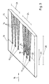
- Fig. 3 shows a body 15 which is flowed towards in the direction of an arrow 16.
- a plurality of interference generators 17 and 18 are arranged on the body 15.
- the disturbance generators 17 are arranged on a line 19 which runs perpendicular or transverse to the inflow.
- Each disturbance generator now again causes the laminar-turbulent boundary layer transition in area 14, with a superposition after a certain run length 20. In this case the laminar-turbulent boundary layer transition has extended to a span-like extension 21.
- the interference generators 18 are also arranged on a further line 22.
- the interference generators 18 lie behind the interference generators 17 in the direction of flow and are arranged offset to them.
- the areas 14 of the interference generators 17 and 18 overlap after a run length 23, which is considerably shorter than the run length 20. It is thus possible to generate the laminar-turbulent boundary layer transition by arranging the interference generators 17 and 18 on the two lines 19 and 22 after the relatively short run length 23 over a span-wide extension 24. This arrangement will preferably be used if, for example, a turbulent boundary layer is desired for profile measurement over the entire span.
Landscapes
- Engineering & Computer Science (AREA)
- Aviation & Aerospace Engineering (AREA)
- Aerodynamic Tests, Hydrodynamic Tests, Wind Tunnels, And Water Tanks (AREA)
- Special Spraying Apparatus (AREA)
Applications Claiming Priority (2)
| Application Number | Priority Date | Filing Date | Title |
|---|---|---|---|
| DE19873738366 DE3738366A1 (de) | 1987-11-12 | 1987-11-12 | Verfahren und vorrichtung zur erzeugung eines laminar-turbulenten grenzschichtuebergangs bei umstroemten koerpern |
| DE3738366 | 1987-11-12 |
Publications (3)
| Publication Number | Publication Date |
|---|---|
| EP0315806A2 EP0315806A2 (de) | 1989-05-17 |
| EP0315806A3 EP0315806A3 (en) | 1990-05-02 |
| EP0315806B1 true EP0315806B1 (de) | 1993-01-20 |
Family
ID=6340306
Family Applications (1)
| Application Number | Title | Priority Date | Filing Date |
|---|---|---|---|
| EP88117387A Expired - Lifetime EP0315806B1 (de) | 1987-11-12 | 1988-10-19 | Verfahren und Vorrichtung zur Erzeugung eines Laminarturbulenten Grenzschichtübergang bei umströmten Körpern |
Country Status (3)
| Country | Link |
|---|---|
| US (1) | US4989810A (enExample) |
| EP (1) | EP0315806B1 (enExample) |
| DE (2) | DE3738366A1 (enExample) |
Families Citing this family (31)
| Publication number | Priority date | Publication date | Assignee | Title |
|---|---|---|---|---|
| DE3738366A1 (de) * | 1987-11-12 | 1989-05-24 | Deutsche Forsch Luft Raumfahrt | Verfahren und vorrichtung zur erzeugung eines laminar-turbulenten grenzschichtuebergangs bei umstroemten koerpern |
| DE4229659C1 (de) * | 1992-09-04 | 1996-04-25 | Daimler Benz Aerospace Ag | Einrichtung zur Erzeugung von ausgedehnten, unregelmäßigen Ultraschallfeldern bei Flugkörpern |
| DE59510549D1 (de) * | 1995-03-14 | 2003-03-13 | Sulzer Markets & Technology Ag | Verfahren zum aktiven Dämpfen globaler Strömungsoszillationen in abgelösten instabilen Strömungen und Vorrichtung zur Anwendung des Verfahrens |
| US5901928A (en) * | 1996-06-14 | 1999-05-11 | Aptek, Inc. | Active turbulence control technique for drag reduction |
| DE19632207A1 (de) * | 1996-08-09 | 1998-02-12 | Bmw Rolls Royce Gmbh | Verfahren zur Verhinderung der laminaren Grenzschicht-Ablösung an Turbomaschinen-Schaufeln |
| US5938404A (en) * | 1997-06-05 | 1999-08-17 | Mcdonnell Douglas Helicopter Company | Oscillating air jets on aerodynamic surfaces |
| US6821090B1 (en) * | 1997-06-05 | 2004-11-23 | Mcdonnell Douglas Helicopter Company | Gust alleviation/flutter suppression device |
| US6092990A (en) * | 1997-06-05 | 2000-07-25 | Mcdonnell Douglas Helicopter Company | Oscillating air jets for helicopter rotor aerodynamic control and BVI noise reduction |
| US6543719B1 (en) | 1997-06-05 | 2003-04-08 | Mcdonnell Douglas Helicopter Co. | Oscillating air jets for implementing blade variable twist, enhancing engine and blade efficiency, and reducing drag, vibration, download and ir signature |
| IL121164A (en) * | 1997-06-26 | 2002-03-10 | Univ Ramot | Airfoil with dynamic stall control by oscillatory forcing |
| IT1306612B1 (it) * | 1998-11-11 | 2001-06-18 | Marco Testi | Metodo di interfaccia tra un pilota e le superfici di un aeromobile,attrezzatura di interfaccia per attuare tale metodo e sensori dello |
| DE19906123B4 (de) * | 1999-02-13 | 2004-06-24 | Voith Siemens Hydro Power Generation Gmbh & Co. Kg | Verfahren zur Vergrößerung des Arbeitsbereiches von geführten Strömungen |
| US6109566A (en) * | 1999-02-25 | 2000-08-29 | United Technologies Corporation | Vibration-driven acoustic jet controlling boundary layer separation |
| US6478541B1 (en) | 2001-08-16 | 2002-11-12 | The Boeing Company | Tapered/segmented flaps for rotor blade-vortex interaction (BVI) noise and vibration reduction |
| US6793177B2 (en) * | 2002-11-04 | 2004-09-21 | The Bonutti 2003 Trust-A | Active drag and thrust modulation system and method |
| US6866233B2 (en) * | 2003-01-03 | 2005-03-15 | Orbital Research Inc. | Reconfigurable porous technology for fluid flow control and method of controlling flow |
| US6685143B1 (en) * | 2003-01-03 | 2004-02-03 | Orbital Research Inc. | Aircraft and missile forebody flow control device and method of controlling flow |
| EP1633625A1 (en) * | 2003-06-11 | 2006-03-15 | BAE Systems PLC | Method of controlling vortex bursting |
| FR2859160B1 (fr) * | 2003-09-01 | 2006-11-17 | Renault Sa | Procede de controle de l'ecoulement d'air autour d'un vehicule automobile |
| US20060196638A1 (en) * | 2004-07-07 | 2006-09-07 | Georgia Tech Research Corporation | System and method for thermal management using distributed synthetic jet actuators |
| US20070023169A1 (en) * | 2005-07-29 | 2007-02-01 | Innovative Fluidics, Inc. | Synthetic jet ejector for augmentation of pumped liquid loop cooling and enhancement of pool and flow boiling |
| US7932535B2 (en) * | 2005-11-02 | 2011-04-26 | Nuventix, Inc. | Synthetic jet cooling system for LED module |
| DE102005052930B4 (de) * | 2005-11-03 | 2018-05-30 | Airbus Defence and Space GmbH | Verfahren und Vorrichtung zur Strömungsbeeinflussung |
| US7607470B2 (en) * | 2005-11-14 | 2009-10-27 | Nuventix, Inc. | Synthetic jet heat pipe thermal management system |
| US8030886B2 (en) | 2005-12-21 | 2011-10-04 | Nuventix, Inc. | Thermal management of batteries using synthetic jets |
| US20100206038A1 (en) * | 2009-02-16 | 2010-08-19 | Santiago Vitagliano | Passive Turbulance Control Product for Minimizing Drag and Its Method of Manufacture |
| EP2272753B1 (en) * | 2009-07-06 | 2013-02-27 | EADS Deutschland GmbH | Gas flow control device |
| DE102015107626B4 (de) * | 2015-05-15 | 2019-11-07 | Airbus Defence and Space GmbH | Strömungssteuerungsvorrichtung, Strömungsdynamischer Profilkörper und Strömungssteuerungsverfahren mit Schallwellenerzeugung |
| CN109441720B (zh) * | 2018-12-21 | 2024-07-09 | 沈阳航空航天大学 | 一种薄膜声激励振动式垂直轴风力机叶片 |
| CN119284151B (zh) * | 2024-09-27 | 2025-09-16 | 中国人民解放军空军工程大学 | 一种多路等离子体调控激波边界层干扰的方法 |
| CN120800730A (zh) * | 2025-05-21 | 2025-10-17 | 中国航天空气动力技术研究院 | 一种基于第二模态波幅值判断尖锥转捩位置的方法和系统 |
Family Cites Families (18)
| Publication number | Priority date | Publication date | Assignee | Title |
|---|---|---|---|---|
| DE228939C (enExample) * | ||||
| DE210498C (enExample) * | 1902-01-17 | 1909-06-02 | ||
| DE320481C (de) * | 1913-01-28 | 1920-04-22 | Lucien Maurice | Dampferzeugungsanlage mit von der Feuerung getrennten Waermespeichern |
| US3161385A (en) * | 1960-06-15 | 1964-12-15 | Coleman Kramer Inc | Means and method for stabilizing laminar boundary layer flow |
| US3362663A (en) * | 1966-03-23 | 1968-01-09 | Boeing Co | Reduction of turbulence and drag by mechanical vibrations |
| US3467348A (en) * | 1967-10-10 | 1969-09-16 | Jerome H Lemelson | Aircraft structures and systems |
| DE3210498A1 (de) * | 1982-03-23 | 1983-10-06 | Hans Raehmer | Grenzschichtbeeinflussung von fluiddynamischen wirkflaechen |
| DE3228939C1 (de) * | 1982-08-03 | 1983-11-24 | Messerschmitt-Bölkow-Blohm GmbH, 8000 München | Verfahren und Einrichtung zur Beeinflussung der Grenzschicht von umstroemten Koerpern |
| US4813631A (en) * | 1982-09-13 | 1989-03-21 | The Boeing Company | Laminar flow control airfoil |
| DE3316392A1 (de) * | 1983-05-05 | 1984-11-08 | Messerschmitt-Bölkow-Blohm GmbH, 8000 München | Einrichtung zur beeinflussung der grenzschicht von umstroemten koerpern bei vorwiegend stochastischen stroemungsschwankungen |
| DE3320481A1 (de) * | 1983-06-07 | 1984-12-13 | Deutsche Forschungs- und Versuchsanstalt für Luft- und Raumfahrt e.V., 5000 Köln | Verfahren und vorrichtung zur beeinflussung der stroemung an aerodynamischen profilen |
| GB2188397B (en) * | 1984-09-13 | 1988-12-29 | Rolls Royce | A low drag surface construction |
| DE3441554A1 (de) * | 1984-11-14 | 1986-05-22 | Deutsche Forschungs- und Versuchsanstalt für Luft- und Raumfahrt e.V., 5300 Bonn | Verminderten stroemungswiderstand aufweisende oberflaeche eines turbulent ueberstroemten koerpers |
| US4741498A (en) * | 1986-09-11 | 1988-05-03 | Northrop Corporation | Ultrasonic drag reduction and lift increase |
| US4802642A (en) * | 1986-10-14 | 1989-02-07 | The Boeing Company | Control of laminar flow in fluids by means of acoustic energy |
| US4848701A (en) * | 1987-06-22 | 1989-07-18 | Belloso Gregorio M | Vertical take-off and landing aircraft |
| DE3738366A1 (de) * | 1987-11-12 | 1989-05-24 | Deutsche Forsch Luft Raumfahrt | Verfahren und vorrichtung zur erzeugung eines laminar-turbulenten grenzschichtuebergangs bei umstroemten koerpern |
| US4786020A (en) * | 1988-01-29 | 1988-11-22 | The United States Of America As Represented By The Secretary Of The Air Force | System for boundary layer control through pulsed heating of a strip heater |
-
1987
- 1987-11-12 DE DE19873738366 patent/DE3738366A1/de active Granted
-
1988
- 1988-10-19 DE DE8888117387T patent/DE3877701D1/de not_active Expired - Fee Related
- 1988-10-19 EP EP88117387A patent/EP0315806B1/de not_active Expired - Lifetime
- 1988-11-17 US US07/272,627 patent/US4989810A/en not_active Expired - Fee Related
Non-Patent Citations (1)
| Title |
|---|
| J. Fluid Mech. (1982), Vol. 118, pp. 187-200; "Control of laminar-instability waves using a new technique" by H.W. Liepmann and AI. * |
Also Published As
| Publication number | Publication date |
|---|---|
| EP0315806A3 (en) | 1990-05-02 |
| EP0315806A2 (de) | 1989-05-17 |
| US4989810A (en) | 1991-02-05 |
| DE3738366C2 (enExample) | 1989-08-17 |
| DE3877701D1 (de) | 1993-03-04 |
| DE3738366A1 (de) | 1989-05-24 |
Similar Documents
| Publication | Publication Date | Title |
|---|---|---|
| DE3738366C2 (enExample) | ||
| DE3779550T3 (de) | Laminarströmungskontrolle in Fluiden durch akustische Energie. | |
| DE3228939C1 (de) | Verfahren und Einrichtung zur Beeinflussung der Grenzschicht von umstroemten Koerpern | |
| DE60004492T2 (de) | Vibrationsangetriebener akustischer strahl, der die ablösung der grenzschicht kontrolliert | |
| DE69616103T2 (de) | Verfahren und Vorrichtung zur Steuerung der Wirbelbildung in Grenzschichten und sonstigen Wandnahen-Flussfeldern | |
| DE69833948T2 (de) | Verfahren und Vorrichtung, um Wirbelschleppen eines Flugzeugs zu behandeln | |
| Thomas | The control of boundary-layer transition using a wave-superposition principle | |
| DE69518361T2 (de) | Verfahren zur Steuerung der Wirbelbildung in Grenzschichten und sonstigen Wandnahen-Flussfeldern | |
| EP2064116B1 (de) | Aerodynamischer körper sowie tragflügel mit aerodynamischem körper zur beeinflussung von nachlaufwirbeln | |
| DE60011235T2 (de) | Tangentiell gerichteter, akustischer gasstrahl zur grenzschichtkontrolle | |
| DE69729106T2 (de) | Energiegewinnung aus strömenden fluiden | |
| DE102015107626B4 (de) | Strömungssteuerungsvorrichtung, Strömungsdynamischer Profilkörper und Strömungssteuerungsverfahren mit Schallwellenerzeugung | |
| WO2010086338A2 (de) | Triebwerk, insbesondere cror-antrieb, für ein flugzeug | |
| DE2013161A1 (de) | Steuersystem für Tragflächen mit Druckmittelaus laß | |
| DE1958354A1 (de) | Schichtenkoerperaufbau insbesondere fuer Schalldaempfer von Gasturbinenstrahltriebwerken | |
| DE2445257A1 (de) | Tintenstrahldrucker | |
| DE2049338C3 (de) | Vorrichtung zum Erfassen und Beseitigen von Ablöseschwingungen durch rotierende Abreißströmung an Verdichterschaufeln | |
| DE3320481A1 (de) | Verfahren und vorrichtung zur beeinflussung der stroemung an aerodynamischen profilen | |
| DE602005003219T2 (de) | Verfahren zur Steuerung eines Flugzeugs | |
| EP0000721A1 (de) | Vorrichtung zum Aufwickeln von Garn | |
| DE4441217C2 (de) | Verfahren zur Dämpfung von Druckstößen sowie Vorrichtung zur Durchführung des Verfahrens | |
| DE19735269C1 (de) | Vorrichtung zur Beeinflussung der Ablösung einer Strömung von einem umströmten Körper | |
| EP1247735B1 (de) | Verfahren zur Reduzierung von Schwingungen in einem Hohlraum und überströmte Flächenanordnung | |
| DE2340120C2 (de) | Ablenkeinrichtung für einen Tintenstrahlschreiber | |
| DE3106144A1 (de) | Kontrollvorrichtung fuer den aufzeichnungstraeger in druckern |
Legal Events
| Date | Code | Title | Description |
|---|---|---|---|
| PUAI | Public reference made under article 153(3) epc to a published international application that has entered the european phase |
Free format text: ORIGINAL CODE: 0009012 |
|
| AK | Designated contracting states |
Kind code of ref document: A2 Designated state(s): DE FR GB |
|
| RAP1 | Party data changed (applicant data changed or rights of an application transferred) |
Owner name: DEUTSCHE FORSCHUNGSANSTALT FUER LUFT- UND RAUMFAHR |
|
| RAP1 | Party data changed (applicant data changed or rights of an application transferred) |
Owner name: DEUTSCHE FORSCHUNGS- UND VERSUCHSANSTALT FUER LUFT |
|
| PUAL | Search report despatched |
Free format text: ORIGINAL CODE: 0009013 |
|
| AK | Designated contracting states |
Kind code of ref document: A3 Designated state(s): DE FR GB |
|
| 17P | Request for examination filed |
Effective date: 19900507 |
|
| 17Q | First examination report despatched |
Effective date: 19910516 |
|
| RAP1 | Party data changed (applicant data changed or rights of an application transferred) |
Owner name: DEUTSCHE FORSCHUNGSANSTALT FUER LUFT- UND RAUMFAHR |
|
| RTI1 | Title (correction) | ||
| GRAA | (expected) grant |
Free format text: ORIGINAL CODE: 0009210 |
|
| AK | Designated contracting states |
Kind code of ref document: B1 Designated state(s): DE FR GB |
|
| GBT | Gb: translation of ep patent filed (gb section 77(6)(a)/1977) |
Effective date: 19930202 |
|
| REF | Corresponds to: |
Ref document number: 3877701 Country of ref document: DE Date of ref document: 19930304 |
|
| ET | Fr: translation filed | ||
| PLBE | No opposition filed within time limit |
Free format text: ORIGINAL CODE: 0009261 |
|
| STAA | Information on the status of an ep patent application or granted ep patent |
Free format text: STATUS: NO OPPOSITION FILED WITHIN TIME LIMIT |
|
| 26N | No opposition filed | ||
| PGFP | Annual fee paid to national office [announced via postgrant information from national office to epo] |
Ref country code: DE Payment date: 19981002 Year of fee payment: 11 |
|
| PGFP | Annual fee paid to national office [announced via postgrant information from national office to epo] |
Ref country code: GB Payment date: 19981005 Year of fee payment: 11 |
|
| PGFP | Annual fee paid to national office [announced via postgrant information from national office to epo] |
Ref country code: FR Payment date: 19981019 Year of fee payment: 11 |
|
| PG25 | Lapsed in a contracting state [announced via postgrant information from national office to epo] |
Ref country code: GB Free format text: LAPSE BECAUSE OF NON-PAYMENT OF DUE FEES Effective date: 19991019 |
|
| GBPC | Gb: european patent ceased through non-payment of renewal fee |
Effective date: 19991019 |
|
| PG25 | Lapsed in a contracting state [announced via postgrant information from national office to epo] |
Ref country code: FR Free format text: LAPSE BECAUSE OF NON-PAYMENT OF DUE FEES Effective date: 20000630 |
|
| PG25 | Lapsed in a contracting state [announced via postgrant information from national office to epo] |
Ref country code: DE Free format text: LAPSE BECAUSE OF NON-PAYMENT OF DUE FEES Effective date: 20000801 |
|
| REG | Reference to a national code |
Ref country code: FR Ref legal event code: ST |