EP0310841B1 - Dreiwegearmatur - Google Patents
Dreiwegearmatur Download PDFInfo
- Publication number
- EP0310841B1 EP0310841B1 EP19880115264 EP88115264A EP0310841B1 EP 0310841 B1 EP0310841 B1 EP 0310841B1 EP 19880115264 EP19880115264 EP 19880115264 EP 88115264 A EP88115264 A EP 88115264A EP 0310841 B1 EP0310841 B1 EP 0310841B1
- Authority
- EP
- European Patent Office
- Prior art keywords
- sliding plate
- pipe connector
- shut
- housing cover
- unit
- Prior art date
- Legal status (The legal status is an assumption and is not a legal conclusion. Google has not performed a legal analysis and makes no representation as to the accuracy of the status listed.)
- Expired - Lifetime
Links
Images
Classifications
-
- F—MECHANICAL ENGINEERING; LIGHTING; HEATING; WEAPONS; BLASTING
- F16—ENGINEERING ELEMENTS AND UNITS; GENERAL MEASURES FOR PRODUCING AND MAINTAINING EFFECTIVE FUNCTIONING OF MACHINES OR INSTALLATIONS; THERMAL INSULATION IN GENERAL
- F16K—VALVES; TAPS; COCKS; ACTUATING-FLOATS; DEVICES FOR VENTING OR AERATING
- F16K11/00—Multiple-way valves, e.g. mixing valves; Pipe fittings incorporating such valves
- F16K11/02—Multiple-way valves, e.g. mixing valves; Pipe fittings incorporating such valves with all movable sealing faces moving as one unit
- F16K11/06—Multiple-way valves, e.g. mixing valves; Pipe fittings incorporating such valves with all movable sealing faces moving as one unit comprising only sliding valves, i.e. sliding closure elements
- F16K11/065—Multiple-way valves, e.g. mixing valves; Pipe fittings incorporating such valves with all movable sealing faces moving as one unit comprising only sliding valves, i.e. sliding closure elements with linearly sliding closure members
- F16K11/0655—Multiple-way valves, e.g. mixing valves; Pipe fittings incorporating such valves with all movable sealing faces moving as one unit comprising only sliding valves, i.e. sliding closure elements with linearly sliding closure members with flat slides
-
- Y—GENERAL TAGGING OF NEW TECHNOLOGICAL DEVELOPMENTS; GENERAL TAGGING OF CROSS-SECTIONAL TECHNOLOGIES SPANNING OVER SEVERAL SECTIONS OF THE IPC; TECHNICAL SUBJECTS COVERED BY FORMER USPC CROSS-REFERENCE ART COLLECTIONS [XRACs] AND DIGESTS
- Y10—TECHNICAL SUBJECTS COVERED BY FORMER USPC
- Y10T—TECHNICAL SUBJECTS COVERED BY FORMER US CLASSIFICATION
- Y10T137/00—Fluid handling
- Y10T137/8593—Systems
- Y10T137/86493—Multi-way valve unit
- Y10T137/86574—Supply and exhaust
- Y10T137/8667—Reciprocating valve
-
- Y—GENERAL TAGGING OF NEW TECHNOLOGICAL DEVELOPMENTS; GENERAL TAGGING OF CROSS-SECTIONAL TECHNOLOGIES SPANNING OVER SEVERAL SECTIONS OF THE IPC; TECHNICAL SUBJECTS COVERED BY FORMER USPC CROSS-REFERENCE ART COLLECTIONS [XRACs] AND DIGESTS
- Y10—TECHNICAL SUBJECTS COVERED BY FORMER USPC
- Y10T—TECHNICAL SUBJECTS COVERED BY FORMER US CLASSIFICATION
- Y10T137/00—Fluid handling
- Y10T137/8593—Systems
- Y10T137/86493—Multi-way valve unit
- Y10T137/86879—Reciprocating valve unit
Definitions
- the invention relates generically to a three-way valve, with a pressure-resistant housing, valve seat, shut-off element movably held therein and an actuating element for the shut-off element guided through a shaft seal, the housing being designed with three pipe connection openings and the valve seat having associated connection bores, the shut-off element being one Has through hole through which two pipe connection openings can be alternately connected to the third pipe connection opening to form a through channel, and wherein the shut-off element seals the pipe connection openings against each other in a further control position.
- the known generic valve is designed as a ball valve with a valve seat made of an elastomer (GB-A 21 37 735).
- the various control positions can be set by turning the valve ball.
- an arbitrary agreement must be made which assigns the position of the hand lever to the flow path.
- a further disadvantage of the known three-way valve is that the sealing surfaces on the valve ball are relatively small and, particularly in the case of corrosive and / or abrasive media, a sufficient service life cannot be guaranteed. Leakages can lead to considerable problems if the three-way valve is to be used to regulate or dose media that must not come into contact with one another.
- the invention has for its object to provide a three-way valve with good sealing properties, in which the risk of incorrect operation is small.
- the aim of the result is that when dosing or regulating different media, undesired mixing does not occur due to incorrect operation or leakage.
- the shut-off element is designed as a slide plate and the valve seat has two sealing washers, between which the slide plate is arranged to be movable up and down, that the sealing washers each have two connecting bores arranged at a control distance from one another, the connecting bores of one sealing washer Connect a common pipe connection opening and a pipe connection opening is assigned to the connection bores of the other sealing washer, and the control distance is at least twice as large as the diameter of the through hole in the slide plate.
- a flow path is released in a lower control position and in an upper control position. In the middle control position, both passageways are blocked.
- the actuating element is axially adjusted.
- the control position can be recognized on the basis of the actuating path of the actuating element.
- the invention is based on the knowledge that in the slide valve according to the invention the spatial assignment between the pipe connection openings and the travel of the actuating element can be recognized by the person skilled in the art without requiring a special agreement.
- the invention surprisingly uses the kinematics of slide fittings with up and down movable slide plates for the purpose of improving the safety of three-way fittings. Because of the flat sealing surfaces between the slide plate and the sealing washers, a good sealing effect can also be achieved, in comparison with spherically ground sealing surfaces, with less manufacturing effort.
- the sealing washers are designed differently and the sealing washer connecting to the common pipe connection opening has only one connection hole which extends from the lower control position to the upper control position, the connection bore of this sealing washer being round or also slit-shaped can.
- the sealing washers of the valve seat are identical and each have two "connection bores at the control distance, the connection bores of one sealing washer connecting to a common pipe connection opening and the connection bores of the other sealing washer being assigned a pipe connection opening.
- the three-way valve according to the invention is characterized in that the housing is formed with a front housing cover and a rear housing cover, that the front housing cover has a collecting space from which holes to the connection bores of the sealing washer, and that the rear housing cover is equipped with flow channels, which Connect the connection bores of the sealing washer with an assigned pipe connection opening, the flow cross-sections of the bores of the front ren housing cover and the flow channels in the rear housing cover of the same size.
- This embodiment also has the advantage that the direction of flow is easily reversible and the pipe connection opening of the front housing cover optionally defines the inlet side or outlet side.
- the invention recommends that the slide plate and the sealing washers are made of sintered ceramic material and that the sealing washers bear against elastomeric housing seals, each of which surrounds an associated connection bore in a ring.
- the elastomer housing seals do not come into contact with the flowing media and are also not exposed to shear stress from the slide plate when the slide plate is actuated. It is therefore possible to use elastomeric seals with a lower seal strength.
- the choice of materials can only be made from the point of view of corrosion resistance and / or temperature resistance.
- the control distance between the connection bores should be at least twice as large as the diameter of the through bore in the slide plate.
- the three-way valve according to the invention is characterized by a good seal, and in the preferred embodiment with sintered ceramic sealing disks and low-sintered ceramic slide plate, it can also be used with corrosive and / or abrasive media and in a wide temperature range.
- the three-way valve according to the invention enables the safe shut-off, dosing and regulation of different media in alternation, which must not come into contact with one another. This applies in particular to corrosive and abrasive media with high temperatures.
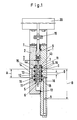
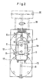
- the basic structure of the three-way valve shown in the figures includes a pressure-resistant housing 1 with a front housing cover 2 and rear housing cover 3, a valve seat 5 consisting of two sealing washers 4a, 4b, a shut-off element 6 held therein in the form of a slide plate and a shaft seal 7 by Housing 1 passed through actuating element 8 for the slide plate 6.
- the housing 1 is formed with three pipe connection openings 9, 10, that the valve seat 5 has associated connection bores 11 and the shut-off element 6 has a through bore 12.
- the arrangement is such that two pipe connection openings 9 can be alternately connected to the third pipe connection opening 10 to form a through-channel.
- connection bores 11 of the sealing washers 4 are arranged at a control distance A which is greater than the diameter D of the through bore 12 of the slide plate 6.
- the shut-off element 6 can assume a further control position, which is shown in FIG. 1, in which the pipe connection openings 9, 10 are sealed against each other.
- the housing 1 is formed in two parts.
- the front housing cover 2 and the rear housing cover 3 are screwed together with the interposition of a cover seal 13.
- the sealing washers 4a, 4b are identical.
- the front housing cover 2 has a collecting space 14 which adjoins the pipe connection opening 10 and from which bores 15 lead to the connection bores 11 of the sealing washer 4a.
- the rear housing cover 3 is equipped with flow channels 16 which connect the connection bores 11 of the sealing washer 4b to an associated pipe connection opening 9.
- the flow cross sections of the bores 15 of the front housing cover 2 and the flow channels 16 in the rear housing cover 3 are of the same size.
- the flow channels 16 are arranged in the rear housing cover 3 in such a way that the pipe connection openings 9 are at a distance B required for connecting pipes.
- the housing cover 2, 3 are formed with sealing surfaces and standardized pipe flanges 17 can be connected.
- the slide plate 6 and the sealing washers 4a, 4b are made of sintered ceramic material.
- the sealing washers 4a, 4b are supported on elastomeric housing seals 18 and bear against the slide plate 6 with a corresponding sealing force.
- the elastomeric housing seals 18 each surround an associated connection bore 11 in a ring shape. O-ring seals with a round or square cross-section are preferably used.
- the control distance A between the connection bores 11 is at least twice as large as the diameter D of the through bore 12 in the slide plate C.
- the actuating element 8 is connected to a lifting device 20 by means of a coupling 19.
Landscapes
- Engineering & Computer Science (AREA)
- General Engineering & Computer Science (AREA)
- Mechanical Engineering (AREA)
- Sliding Valves (AREA)
- Multiple-Way Valves (AREA)
- Gyroscopes (AREA)
- Medicines That Contain Protein Lipid Enzymes And Other Medicines (AREA)
- Ceramic Capacitors (AREA)
Priority Applications (1)
| Application Number | Priority Date | Filing Date | Title |
|---|---|---|---|
| AT88115264T ATE60115T1 (de) | 1987-09-22 | 1988-09-17 | Dreiwegearmatur. |
Applications Claiming Priority (2)
| Application Number | Priority Date | Filing Date | Title |
|---|---|---|---|
| DE19873731754 DE3731754A1 (de) | 1987-09-22 | 1987-09-22 | Dreiwegearmatur |
| DE3731754 | 1987-09-22 |
Publications (2)
| Publication Number | Publication Date |
|---|---|
| EP0310841A1 EP0310841A1 (de) | 1989-04-12 |
| EP0310841B1 true EP0310841B1 (de) | 1991-01-16 |
Family
ID=6336517
Family Applications (1)
| Application Number | Title | Priority Date | Filing Date |
|---|---|---|---|
| EP19880115264 Expired - Lifetime EP0310841B1 (de) | 1987-09-22 | 1988-09-17 | Dreiwegearmatur |
Country Status (6)
| Country | Link |
|---|---|
| US (1) | US4838312A (enExample) |
| EP (1) | EP0310841B1 (enExample) |
| JP (1) | JPH01108477A (enExample) |
| AT (1) | ATE60115T1 (enExample) |
| DE (1) | DE3731754A1 (enExample) |
| ES (1) | ES2020318B3 (enExample) |
Families Citing this family (16)
| Publication number | Priority date | Publication date | Assignee | Title |
|---|---|---|---|---|
| DE3829506A1 (de) * | 1988-08-31 | 1990-03-08 | Berchem & Schaberg Gmbh | Absperrventil, insbesondere regelabsperrventil, fuer rohrleitungen |
| DE4039564C1 (enExample) * | 1990-12-07 | 1992-03-12 | Mannesmann Ag, 4000 Duesseldorf, De | |
| NL1008703C1 (nl) * | 1998-01-08 | 1999-07-12 | Jan Hendrik Fondse | Meerwegklep. |
| US7959780B2 (en) | 2004-07-26 | 2011-06-14 | Emporia Capital Funding Llc | Textured ion exchange membranes |
| US20060137986A1 (en) * | 2004-12-23 | 2006-06-29 | Pionetics Corporation | Fluid flow controlling valve having seal with reduced leakage |
| US7780833B2 (en) | 2005-07-26 | 2010-08-24 | John Hawkins | Electrochemical ion exchange with textured membranes and cartridge |
| BRPI0616890A2 (pt) | 2005-10-06 | 2011-07-05 | Pionetics Corp | aparelho de tratamento de fluido, e, métodos de tratamento de um fluido, de filtração de fluido em uma célula eletroquìmica, e de operação de uma célula eletroquìmica |
| US7845620B1 (en) * | 2006-12-20 | 2010-12-07 | Bouldin Corporation | Outfeed gate with wear strip assembly |
| DE102007035775B4 (de) | 2007-07-27 | 2016-07-21 | Knorr-Bremse Systeme für Nutzfahrzeuge GmbH | Vorgesteuertes Ventil mit keramischem Steuerkolben |
| US20100147527A1 (en) * | 2008-12-12 | 2010-06-17 | Paulo Cezar Silva Paulo | Subsea boosting cap system |
| AU2011311175B2 (en) | 2010-10-07 | 2016-06-30 | Amiad Water Systems Ltd. | Fluid filtering unit and system |
| DE102013224453A1 (de) * | 2013-11-28 | 2015-05-28 | Marco Systemanalyse Und Entwicklung Gmbh | Ventil zur Dosierung von Medien im Kleinstmengenbereich |
| DE102014113418A1 (de) * | 2014-09-17 | 2016-03-17 | Franke Aquarotter GmbH | Ventilanordnung mit keramischen Ventilscheiben für eine Sanitärarmatur |
| CN105114662A (zh) * | 2015-09-17 | 2015-12-02 | 青岛欣鑫数控精密机械有限公司 | 负压吸附真空换向阀 |
| BR102016012918A2 (pt) * | 2016-06-06 | 2017-12-19 | Fmc Technologies Do Brasil Ltda | Directional drawer type lock valve |
| CN114776834B (zh) * | 2022-03-14 | 2023-11-24 | 厦门欧圣斯卫浴有限公司 | 一种三通阀切换结构 |
Family Cites Families (16)
| Publication number | Priority date | Publication date | Assignee | Title |
|---|---|---|---|---|
| US2743900A (en) * | 1952-11-28 | 1956-05-01 | Parker Appliance Co | Slide valve |
| US3007492A (en) * | 1958-11-17 | 1961-11-07 | Otis Eng Co | Fluid flow systems and pilot valves therefor |
| US3324888A (en) * | 1964-10-23 | 1967-06-13 | Republic Mfg Company | Three-way, two-position valve |
| US3428073A (en) * | 1966-07-21 | 1969-02-18 | Honeywell Inc | Safe leak valve |
| US3463192A (en) * | 1967-11-29 | 1969-08-26 | Erich Herion Sr | Slide valve |
| US3521674A (en) * | 1968-06-24 | 1970-07-28 | Beckman Instruments Inc | Sampling valve |
| BE755988A (fr) * | 1969-10-20 | 1971-02-15 | Stiltner Marshall A | Joint de soupape |
| US3788354A (en) * | 1972-05-30 | 1974-01-29 | P Symmons | Single handle water mixing valve |
| JPS53103231A (en) * | 1977-02-21 | 1978-09-08 | Toto Ltd | Valve |
| FR2407410A1 (fr) * | 1977-10-27 | 1979-05-25 | Gaudin Henri | Distributeur pneumatique ou hydraulique a tiroir prismatique et corps en deux parties |
| NL193670C (nl) * | 1982-10-15 | 2000-06-06 | Vsh Fabrieken Bv | Drieweg kogelkraan. |
| US4548238A (en) * | 1983-12-19 | 1985-10-22 | Chorkey William J | Directional control valve with straight through flow |
| DE3347135C2 (de) * | 1983-12-27 | 1986-04-03 | Ideal-Standard Gmbh, 5300 Bonn | Durchgangs- oder Mehrwege-Ventil in Plattenbauweise |
| JPH0227550B2 (ja) * | 1985-03-29 | 1990-06-18 | Kubota Ltd | Ganfuntaigasuyoben |
| JPS61286671A (ja) * | 1985-06-12 | 1986-12-17 | Gadelius Kk | セラミツク製弁部材を有するバルブ |
| DE3636423A1 (de) * | 1986-10-25 | 1988-04-28 | Mueller Umwelttechnik | Schalt- und sicherheitsventil fuer hochdruck-spuelanlagen, beispielsweise in kommunalfahrzeugen |
-
1987
- 1987-09-22 DE DE19873731754 patent/DE3731754A1/de active Granted
-
1988
- 1988-09-12 JP JP63226728A patent/JPH01108477A/ja active Pending
- 1988-09-17 AT AT88115264T patent/ATE60115T1/de not_active IP Right Cessation
- 1988-09-17 ES ES88115264T patent/ES2020318B3/es not_active Expired - Lifetime
- 1988-09-17 EP EP19880115264 patent/EP0310841B1/de not_active Expired - Lifetime
- 1988-09-20 US US07/247,113 patent/US4838312A/en not_active Expired - Fee Related
Also Published As
| Publication number | Publication date |
|---|---|
| EP0310841A1 (de) | 1989-04-12 |
| DE3731754C2 (enExample) | 1989-08-10 |
| JPH01108477A (ja) | 1989-04-25 |
| ATE60115T1 (de) | 1991-02-15 |
| US4838312A (en) | 1989-06-13 |
| DE3731754A1 (de) | 1989-04-20 |
| ES2020318B3 (es) | 1991-08-01 |
Similar Documents
| Publication | Publication Date | Title |
|---|---|---|
| EP0310841B1 (de) | Dreiwegearmatur | |
| DE2606952C2 (enExample) | ||
| DE2923074C2 (de) | Schieber mit geräuschdämmenden Einbauten | |
| DE69920110T2 (de) | Schieberanordnung für Doppelsitzschiebeventil | |
| AT393041B (de) | Thermostatisches mischventil | |
| DE102010050953A1 (de) | Strömungsmengenregler | |
| DE3137774A1 (de) | Dichtungsanordnung fuer den anschluss von keramikventilgliedern | |
| DE4143309C2 (de) | Kugelhahn V | |
| EP0220358B1 (de) | Sanitäres Ventil | |
| EP0187222A1 (de) | Ventilsteuereinrichtung für ein zahnärztliches Gerät | |
| DE3540997C2 (enExample) | ||
| DE8800059U1 (de) | Dreiwegearmatur | |
| DE1650504A1 (de) | Ventileinheit | |
| DE3633995C2 (enExample) | ||
| DE2837756A1 (de) | Ventil | |
| DE4039644A1 (de) | Ueberstroemventil | |
| DE3935389A1 (de) | Mischventil | |
| DE3034481C2 (de) | Ventilanordnung | |
| EP0165467A2 (de) | Regelarmatur für Gasgeräte | |
| DE8632731U1 (de) | Kugelhahn mit sinterkeramischen Sitzringen und sinterkeramischer Ventilkugel | |
| DE3140353A1 (de) | Regel- und absperrventil | |
| DE4425599C2 (de) | Schlauchventil mit einem ein zu schaltendes Fluidum umgebenden Schlauchelement | |
| DE19516336B4 (de) | Wasserhahn und Ventilelement für den Hahn | |
| CH642434A5 (de) | Ventil. | |
| DE102021103392A1 (de) | Servoventil |
Legal Events
| Date | Code | Title | Description |
|---|---|---|---|
| PUAI | Public reference made under article 153(3) epc to a published international application that has entered the european phase |
Free format text: ORIGINAL CODE: 0009012 |
|
| AK | Designated contracting states |
Kind code of ref document: A1 Designated state(s): AT BE CH DE ES FR GB GR IT LI LU NL SE |
|
| RBV | Designated contracting states (corrected) |
Designated state(s): AT CH ES FR GB IT LI NL |
|
| REG | Reference to a national code |
Ref country code: DE Ref legal event code: 8566 |
|
| 17P | Request for examination filed |
Effective date: 19890520 |
|
| 17Q | First examination report despatched |
Effective date: 19900202 |
|
| GRAA | (expected) grant |
Free format text: ORIGINAL CODE: 0009210 |
|
| AK | Designated contracting states |
Kind code of ref document: B1 Designated state(s): AT CH ES FR GB IT LI NL |
|
| REF | Corresponds to: |
Ref document number: 60115 Country of ref document: AT Date of ref document: 19910215 Kind code of ref document: T |
|
| ITF | It: translation for a ep patent filed | ||
| GBT | Gb: translation of ep patent filed (gb section 77(6)(a)/1977) | ||
| ET | Fr: translation filed | ||
| PLBE | No opposition filed within time limit |
Free format text: ORIGINAL CODE: 0009261 |
|
| STAA | Information on the status of an ep patent application or granted ep patent |
Free format text: STATUS: NO OPPOSITION FILED WITHIN TIME LIMIT |
|
| 26N | No opposition filed | ||
| PGFP | Annual fee paid to national office [announced via postgrant information from national office to epo] |
Ref country code: CH Payment date: 19940926 Year of fee payment: 7 Ref country code: AT Payment date: 19940926 Year of fee payment: 7 |
|
| PGFP | Annual fee paid to national office [announced via postgrant information from national office to epo] |
Ref country code: NL Payment date: 19940930 Year of fee payment: 7 |
|
| PGFP | Annual fee paid to national office [announced via postgrant information from national office to epo] |
Ref country code: GB Payment date: 19950907 Year of fee payment: 8 |
|
| PGFP | Annual fee paid to national office [announced via postgrant information from national office to epo] |
Ref country code: ES Payment date: 19950912 Year of fee payment: 8 |
|
| PG25 | Lapsed in a contracting state [announced via postgrant information from national office to epo] |
Ref country code: AT Effective date: 19950917 |
|
| PGFP | Annual fee paid to national office [announced via postgrant information from national office to epo] |
Ref country code: FR Payment date: 19950926 Year of fee payment: 8 |
|
| PG25 | Lapsed in a contracting state [announced via postgrant information from national office to epo] |
Ref country code: LI Effective date: 19950930 Ref country code: CH Effective date: 19950930 |
|
| PG25 | Lapsed in a contracting state [announced via postgrant information from national office to epo] |
Ref country code: NL Effective date: 19960401 |
|
| REG | Reference to a national code |
Ref country code: CH Ref legal event code: PL |
|
| NLV4 | Nl: lapsed or anulled due to non-payment of the annual fee |
Effective date: 19960401 |
|
| PG25 | Lapsed in a contracting state [announced via postgrant information from national office to epo] |
Ref country code: GB Effective date: 19960917 |
|
| PG25 | Lapsed in a contracting state [announced via postgrant information from national office to epo] |
Ref country code: ES Free format text: LAPSE BECAUSE OF THE APPLICANT RENOUNCES Effective date: 19960918 |
|
| PG25 | Lapsed in a contracting state [announced via postgrant information from national office to epo] |
Ref country code: FR Effective date: 19960930 |
|
| GBPC | Gb: european patent ceased through non-payment of renewal fee |
Effective date: 19960917 |
|
| REG | Reference to a national code |
Ref country code: FR Ref legal event code: ST |
|
| REG | Reference to a national code |
Ref country code: FR Ref legal event code: ST |
|
| REG | Reference to a national code |
Ref country code: ES Ref legal event code: FD2A Effective date: 19991007 |
|
| PG25 | Lapsed in a contracting state [announced via postgrant information from national office to epo] |
Ref country code: IT Free format text: LAPSE BECAUSE OF NON-PAYMENT OF DUE FEES Effective date: 20050917 |