EP0310792A2 - Anzeigelampe zum Einbau in Leiterplatten - Google Patents
Anzeigelampe zum Einbau in Leiterplatten Download PDFInfo
- Publication number
- EP0310792A2 EP0310792A2 EP88113348A EP88113348A EP0310792A2 EP 0310792 A2 EP0310792 A2 EP 0310792A2 EP 88113348 A EP88113348 A EP 88113348A EP 88113348 A EP88113348 A EP 88113348A EP 0310792 A2 EP0310792 A2 EP 0310792A2
- Authority
- EP
- European Patent Office
- Prior art keywords
- base
- tabs
- indicator lamp
- power supply
- lamp according
- Prior art date
- Legal status (The legal status is an assumption and is not a legal conclusion. Google has not performed a legal analysis and makes no representation as to the accuracy of the status listed.)
- Granted
Links
Images


Classifications
-
- H—ELECTRICITY
- H01—ELECTRIC ELEMENTS
- H01R—ELECTRICALLY-CONDUCTIVE CONNECTIONS; STRUCTURAL ASSOCIATIONS OF A PLURALITY OF MUTUALLY-INSULATED ELECTRICAL CONNECTING ELEMENTS; COUPLING DEVICES; CURRENT COLLECTORS
- H01R33/00—Coupling devices specially adapted for supporting apparatus and having one part acting as a holder providing support and electrical connection via a counterpart which is structurally associated with the apparatus, e.g. lamp holders; Separate parts thereof
- H01R33/05—Two-pole devices
- H01R33/20—Two-pole devices having concentrically or coaxially arranged contacts
- H01R33/205—Two-pole devices having concentrically or coaxially arranged contacts secured to structure or printed circuit board
-
- H—ELECTRICITY
- H01—ELECTRIC ELEMENTS
- H01K—ELECTRIC INCANDESCENT LAMPS
- H01K1/00—Details
- H01K1/42—Means forming part of the lamp for the purpose of providing electrical connection, or support for, the lamp
- H01K1/46—Means forming part of the lamp for the purpose of providing electrical connection, or support for, the lamp supported by a separate part, e.g. base, cap
-
- F—MECHANICAL ENGINEERING; LIGHTING; HEATING; WEAPONS; BLASTING
- F21—LIGHTING
- F21V—FUNCTIONAL FEATURES OR DETAILS OF LIGHTING DEVICES OR SYSTEMS THEREOF; STRUCTURAL COMBINATIONS OF LIGHTING DEVICES WITH OTHER ARTICLES, NOT OTHERWISE PROVIDED FOR
- F21V19/00—Fastening of light sources or lamp holders
- F21V19/001—Fastening of light sources or lamp holders the light sources being semiconductors devices, e.g. LEDs
Definitions
- the invention relates to an indicator lamp for installation in printed circuit boards according to the preamble of claim 1.
- Lamps of this type are used in particular for illuminating dashboards, for example in motor vehicles or aircraft.
- Such an indicator lamp is known for example from DE-OS 28 24 107 and 30 20 309, wherein the power supply wires are soldered or welded to the base contacts. In the first case, the two parts are joined together before the lamp bulb is installed, and in the second case after the installation.
- a disadvantage of this type of assembly is that the security of the electrical connection is not guaranteed to the desired extent, since the welding points during assembly of the lamp bulb and during operation due to the constant mechanical stress (for example vibrations occurring during travel or flight) to be able to solve.
- the object of the invention is to provide an indicator lamp with a base made of insulating material, in which the reliability of the connection between the power supply wires and the base contacts is improved.
- the invention advantageously achieves an inseparable connection with high contact reliability.
- the electrical contact is made through the welding spots.
- the fixation of the end of the power supply which is achieved by the form-fitting of the tabs, acts as a positioning aid during the welding process.
- a fusion weld achieved using a laser is advantageously used.
- an alloy is formed in the area of the welding point between the materials of the power supply and the base contact.
- the quality of the connection can be improved in that the material of the base contact is matched to the material of the power supply wire (F-wire).
- a special treatment of the material e.g. nickel plating or copper plating
- the material which is particularly preferred for the base contacts chrome-nickel-alloyed stainless steel, ensures not only the willingness to alloy but also corrosion protection, without the need for special pre- or post-treatment.
- the non-contact weld can also be used in relatively inaccessible places.
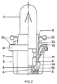
- the indicator lamp shown schematically in FIGS. 1 and 2 is a small incandescent lamp with a lamp bulb 1 which fits into the receptacle 4 of a base 2 is used.
- the piston 1 is provided with a pinch 3.
- the pump connector 5 is melted off in the middle, while a power supply 6 (only one is visible in the figures) is led out to the side of it, on the broad sides of the pinch 3.
- the power supplies are made of copper sheathed wire with a diameter of approx. 0.3 to 0.35 mm. They are bent outwards in a U-shape.
- the base 2 consists of an approximately cubic plastic body 7 with chamfered corners, on which a cylindrical flange 8 rotates at the top. Socket contacts 10 are held in two opposite vertical slots 9 in the body 7 by means of resilient tabs 11.
- the lamp bulb 1 is centered in the base 2 by elastic webs (not visible) which are integrated in the base, similar to that described in EP-PS 70 014.
- the lower region of the base contacts 10, including the tabs 11, can be viewed through a rectangular window 13 in the body 7.
- each base contact 10 At the lower end of each base contact 10, a pair of tabs 14 is integrally formed, which includes the upwardly bent ends 15 of the power supply 6 on the outside of the base contacts 10 in a form-fitting manner.
- the two tabs 14 are dimensioned so that a joint 16 remains between them after bending.
- the end 15 of the power supply and the two tabs 14 are connected by two common welding points 17.
- a powerful CO2 or Nd: YAG laser is used for this.
- the window 13 makes it possible to carry out this welding only after the piston has been installed.
- a visual inspection of the connection between the power supply and the tab as well as the spread tab 11 can be carried out in the window.
- the material of the power supply lines and that of the tabs 14 are homogeneously fused together.
- the power supply lies on the inside of the base contact and the tabs are bent inwards accordingly.
- the positive locking and welding takes place before the piston is assembled. With this type of connection, the connection point is particularly well protected.
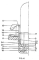
- FIGS. 3 and 4 A further preferred embodiment is shown in FIGS. 3 and 4.
- the same reference numbers correspond to the same features in comparison with FIGS. 1 and 2.
- the base 2 is in this embodiment a hexagonal plastic body 7 'without a window.
- the socket contacts 18 are divided into three to Reduce overall height. They consist of three axially aligned sections 19, 20, 21, which are connected to one another by bevels 22, 23. The bevels are inclined at 45 ° to the longitudinal axis.
- the pair of contact tabs 12 is integrated in a manner similar to that in the first exemplary embodiment. Furthermore, the tabs 11 are attached laterally to the uppermost section 19. Only this uppermost section 19 is guided in the slot 9.
- the first slope 22 sits on a shoulder 24 of the plastic body 7 ', so that the central portion 20 is set back inwards.
- the second bevel 23 extends into the piston-receiving cavity 4 of the plastic body below the height of the pinch 3.
- the tabs 14 are formed laterally on the lowermost section 21 and are bent around the end 15 of the U-shaped curved power supply.
- the welding attachment is carried out in a similar manner as in the first exemplary embodiment on the outside at the lowest section of the base contact before the piston is installed.
- the tabs are cut out of the "meat" of the base contact, similar to the lower contact tab. They are not necessarily molded onto the lower end of the base contacts.
Abstract
Description
- Die Erfindung geht aus von einer Anzeigelampe zum Einbau in Leiterplatten nach dem Oberbegriff des Anspruchs 1.
- Lampen dieser Art werden insbesondere zur Beleuchtung von Armaturenbrettern verwendet, beispielsweise in Kraftfahrzeugen oder Flugzeugen.
- Eine derartige Anzeigelampe ist beispielsweise aus den DE-OS 28 24 107 und 30 20 309 bekannt, wobei die Stromzuführungsdrähte mit den Sockelkontakten verlötet oder verschweißt sind. Das Zusammenfügen der beiden Teile erfolgt hierbei im ersten Fall vor der Montage des Lampenkolbens, im zweiten Fall nach der Montage.
- Nachteilig an dieser Art des Zusammenfügens ist, daß die Sicherheit der elektrischen Verbindung nicht im gewünschten Maße gewährleistet ist, da sich die Schweißstellen während der Montage des Lampenkolbens und im Betrieb aufgrund der ständigen mechanischen Beanspruchung (z.B. während der Fahrt bzw. des Fluges auftretende Vibrationen) lösen können.
- Aufgabe der Erfindung ist es, eine Anzeigelampe mit Sockel aus Isoliermaterial zu schaffen, bei der die Zuverlässigkeit der Verbindung zwischen Stromzuführungsdrähten und Sockelkontakten verbessert wird.
- Diese Aufgabe wird bei einer Anzeigelampe der eingangs erwähnten Art durch die kennzeichnenden Merkmale des Anspruchs 1 gelöst.
- Bevorzugte Ausgestaltungen der Erfindung sind in den Unteransprüchen angegeben.
- Vorteilhaft wird durch die Erfindung eine unlösbare Verbindung mit hoher Kontaktsicherheit erzielt. Der elektrische Kontakt wird durch die Schweißpunkte hergestellt. Hierbei wirkt die durch den Formschluß der Laschen erfolgte Fixierung des Endes der Stromzuführung als Positionierungshilfe beim Schweißvorgang.
- Bei der hier beschriebenen Anzeigelampe ist es darüber hinaus möglich, das Zusammenfügen von Stromzuführung und Sockelkontakt wahlweise vor oder nach der Montage des Lampenkolbens durchzuführen.
- Durch das Freihalten einer Fuge zwischen den Laschen und das Anbringen der Schweißpunkte im Bereich der Fuge wird die Voraussetzung für eine erleichterte, visuelle Prüfmöglichkeit sowie ein Höchstmaß an Kontaktsicherheit der Schweißung geschaffen.
- Vorteilhaft wird eine mittels Laser erzielte Schmelzschweißung angewendet. Hierbei bildet sich im Bereich des Schweißpunktes eine Legierung zwischen den Werkstoffen der Stromzuführung und des Sockelkontaktes.
- Die Qualität der Verbindung läßt sich dadurch verbessern, daß der Werkstoff des Sockelkontaktes auf den Werkstoff des Stromzuführungsdrahtes (F-Draht) abgestimmt ist. Um die Klemmverbindung vor Korrosion zu schützen, wird üblicherweise eine spezielle Behandlung des Werkstoffs (z.B. Vernickeln oder Verkupfern) vorgenommen. Der für die Sockelkontakte besonders bevorzugte Werkstoff, chrom-nickel-legierter Edelstahl, sichert neben der Legierungswilligkeit auch den Korrosionsschutz, ohne daß eine besondere Vor- oder Nachbehandlung erforderlich ist.
- Der Vorteil der Laserschweißung liegt auch in der Möglichkeit der genauen Positionierung der Schweißstelle und des Verwendens massearmer Teile. Beides spielt bei den kleinen Dimensionen von Anzeigelampen eine wesentliche Rolle.
- Die Schweißung, die berührungslos erfolgt, kann auch an relativ unzugänglichen Stellen angewendet werden.
- Zwei Ausführungsbeispiele der Erfindung werden nunmehr anhand von Figuren näher erläutert. Es zeigt:
- Figur 1 eine Anzeigelampe in Seitenansicht
- Figur 2 eine um 90° gedrehte Seitenansicht, teilweise geschnitten
- Figur 3 eine andere Ausführungsform einer Anzeigelampe in Seitenansicht
- Figur 4 eine um 90° gedrehte Seitenansicht der in Figur 3 gezeigten Anzeigelampe im Schnitt
- Die in Figur 1 und 2 schematisch gezeigte Anzeigelampe ist eine Kleinglühlampe mit einem Lampenkolben 1, der in die Aufnahme 4 eines Sockels 2 mit Passung eingesetzt ist. Der Kolben 1 ist mit einer Quetschung 3 versehen. Am unteren Ende der Quetschung 3 ist mittig der Pumpstutzen 5 abgeschmolzen, während seitlich davon, an den Breitseiten der Quetschung 3, jeweils eine Stromzuführung 6 (nur eine ist in den Figuren sichtbar) herausgeführt ist.
- Die Stromzuführungen sind aus Kupfermanteldraht mit einem Durchmesser von ca. 0,3 bis 0,35 mm gefertigt. Sie sind U-förmig nach außen umgebogen.
- Der Sockel 2 besteht aus einem näherungsweise kubischen Kunststoffkörper 7 mit abgeschrägten Ecken, an dem oben ein zylindrischer Flansch 8 umläuft. In zwei einander gegenüberliegenden vertikalen Schlitzen 9 im Körper 7 sind Sockelkontakte 10 mittels federnder Lappen 11 gehaltert. Die Sockelkontakte 10, die aus chrom-nickel-legiertem Edelstahl mit Federeigenschaften gefertigt sind, weisen lampenseitig jeweils ein Paar Kontaktlaschen 12 auf, die aus dem darunter befindlichen Teil des Sockelkontaktes 10 herausgebogen sind, wobei die untere der beiden Laschen 12 jeweils auf einer Kerbe im Flansch 8 aufliegt. Der Abstand der oberen Lasche 12 ergibt sich aus der Dicke der Leiterplatte, in der die Anzeigelampe aufgenommen werden soll.
- Die Zentrierung des Lampenkolbens 1 im Sockel 2 erfolgt durch elastische Stege (nicht sichtbar), die in den Sockel integriert sind, ähnlich wie in der EP-PS 70 014 beschrieben.
- Der untere Bereich der Sockelkontakte 10, einschließlich der Lappen 11, kann jeweils durch ein rechteckiges Fenster 13 im Körper 7 eingesehen werden.
- Am unteren Ende jedes Sockelkontaktes 10 ist ein Laschenpaar 14 angeformt, das die nach oben gebogenen Enden 15 der Stromzuführung 6 an der Außenseite der Sockelkontakte 10 formschlüssig umfaßt. Die beiden Laschen 14 sind dabei so dimensioniert, daß zwischen ihnen nach dem Umbiegen eine Fuge 16 verbleibt. Im Bereich der Fuge 16 ist das Ende 15 der Stromzuführung und die beiden Laschen 14 durch zwei gemeinsame Schweißpunkte 17 verbunden. Hierfür wird ein leistungsstarker CO₂- oder Nd:YAG-Laser verwendet.
- Das Fenster 13 ermöglicht es, diese Schweißung auch erst nach der Montage des Kolbens durchzuführen. Darüber hinaus kann im Fenster sowohl eine Sichtkontrolle der Verbindung Stromzuführung - Lasche als auch der abgespreizten Lappen 11 erfolgen. Im Bereich der Schweißpunkte wird das Material der Stromzuführungen und das der Laschen 14 miteinander homogen verschmolzen.
- Bei einer anderen Ausführungsform liegt die Stromzuführung innen am Sockelkontakt an und die Laschen sind entsprechend nach innen umgebogen. Der Formschluß und das Schweißen erfolgt vor der Montage des Kolbens. Bei dieser Art der Verbindung ist die Verbindungsstelle besonders gut geschützt.
- Eine weitere bevorzugte Ausführungsform zeigt Figur 3 und 4. Hierbei entsprechen im Vergleich mit Figur 1 und 2 gleiche Bezugsziffern den gleichen Merkmalen.
- Der Sockel 2 ist in diesem Ausführungsbeispiel ein Sechskant-Kunststoffkörper 7′ ohne Sichtfenster. Die Sockelkontakte 18 sind dreifach gegliedert, um die Bauhöhe zu reduzieren. Sie bestehen aus drei axial ausgerichteten Abschnitten 19, 20, 21, die durch Schrägen 22, 23 miteinander verbunden sind. Die Schrägen sind um 45° gegen die Längsachse geneigt. Am obersten Abschnitt 19 ist das Kontaktlaschenpaar 12 ähnlich wie im ersten Ausführungsbeispiel integriert. Weiterhin sind auch die Lappen 11 am obersten Abschnitt 19 seitlich angesetzt. Nur dieser oberste Abschnitt 19 ist im Schlitz 9 geführt. Die erste Schräge 22 sitzt auf einer Schulter 24 des Kunststoffkörpers 7′ auf, so daß der Mittelabschnitt 20 nach innen zurückversetzt ist. Die zweite Schräge 23 erstreckt sich in den den Kolben aufnehmenden Hohlraum 4 des Kunststoffkörpers unterhalb der Höhe der Quetschung 3. An den untersten Abschnitt 21 sind seitlich die Laschen 14 angeformt, die um das Ende 15 der U-förmig gebogenen Stromzuführung herumgebogen sind. Die Schweißbefestigung erfolgt in ähnlicher Weise wie beim ersten Ausführungsbeispiel außen am untersten Abschnitt des Sockelkontaktes vor der Montage des Kolbens.
- Die übrigen Merkmale der Lampe sind entsprechend dem ersten Ausführungsbeispiel ausgeführt.
- Die Laschen sind in einer weiteren Ausführungsform ähnlich der unteren Kontaktlasche aus dem "Fleisch" des Sockelkontaktes herausgeschnitten. Sie sind nicht notwendig am unteren Ende der Sockelkontakte angeformt.
Claims (7)
- einem Kleinglühlampenkolben (1)
- einem Leuchtkörper
- Stromzuführungen (6), die den Leuchtkörper haltern und sockelseitig aus dem Lampenkolben herausgeführt sind
- einem Sockel (2) aus Isoliermaterial
- Sockelkontakten (10; 18) aus metallischem, federndem Werkstoff, die axial ausgerichtet und in dafür vorgesehenen Schlitzen (9) des Sockels durch federnde Lappen (11) gehalten sind, wobei an jedem Sockelkontakt das Ende (15) einer Stromzuführung (6) elektrisch-leitend befestigt ist
- Kontaktlaschenpaare (12) an der Oberseite des Sockels (2) zum Befestigen und Kontaktieren der Lampe in der Leiterplatte, die einander gegenüberliegend an den Sockelkontakten (10; 18) ausgebildet sind,
dadurch gekennzeichnet, daß jeder Sockelkontakt (10; 18) ein Paar Laschen (14) aufweist, die formschlüssig um das Ende (15) der Stromzuführung (6) herumgebogen sind, wobei diese Laschen (14) durch Schweißpunkte (17) mit dem Ende (15) der Stromzuführung (6) verbunden sind.
Applications Claiming Priority (2)
| Application Number | Priority Date | Filing Date | Title |
|---|---|---|---|
| DE8712722U | 1987-09-21 | ||
| DE8712722U DE8712722U1 (de) | 1987-09-21 | 1987-09-21 |
Publications (3)
| Publication Number | Publication Date |
|---|---|
| EP0310792A2 true EP0310792A2 (de) | 1989-04-12 |
| EP0310792A3 EP0310792A3 (en) | 1990-04-11 |
| EP0310792B1 EP0310792B1 (de) | 1993-10-20 |
Family
ID=6812279
Family Applications (1)
| Application Number | Title | Priority Date | Filing Date |
|---|---|---|---|
| EP88113348A Expired - Lifetime EP0310792B1 (de) | 1987-09-21 | 1988-08-17 | Anzeigelampe zum Einbau in Leiterplatten |
Country Status (2)
| Country | Link |
|---|---|
| EP (1) | EP0310792B1 (de) |
| DE (2) | DE8712722U1 (de) |
Cited By (5)
| Publication number | Priority date | Publication date | Assignee | Title |
|---|---|---|---|---|
| JPH03116681U (de) * | 1990-03-13 | 1991-12-03 | ||
| FR2669773A1 (fr) * | 1990-11-26 | 1992-05-29 | Socop Sa | Lampe de signalisation et son procede de fabrication. |
| EP0786791A1 (de) * | 1996-01-25 | 1997-07-30 | Patent-Treuhand-Gesellschaft für elektrische Glühlampen mbH | Elektrische Lampe |
| DE19705738A1 (de) * | 1997-02-14 | 1998-08-20 | Trw Fahrzeugelektrik | Leuchtelement, insbesondere zur Beleuchtung von Funktionssymbolen oder zur Signalisierung von Funktionen in Kraftfahrzeugen |
| EP0991096A1 (de) * | 1998-09-30 | 2000-04-05 | Patent-Treuhand-Gesellschaft für elektrische Glühlampen mbH | Elektrische Lampe |
Families Citing this family (2)
| Publication number | Priority date | Publication date | Assignee | Title |
|---|---|---|---|---|
| DE3818019C2 (de) * | 1988-05-27 | 1995-04-06 | Hella Kg Hueck & Co | Leuchte |
| DE10158633A1 (de) * | 2001-11-29 | 2003-06-12 | Hella Kg Hueck & Co | Befestigungsvorrichtung für Lichtquellen in Fahrzeugleuchten |
Citations (5)
| Publication number | Priority date | Publication date | Assignee | Title |
|---|---|---|---|---|
| US3717842A (en) * | 1971-02-26 | 1973-02-20 | Perfection Electrical Prod Inc | Method of connecting aluminum wire to electrical terminals |
| GB2022233A (en) * | 1978-06-01 | 1979-12-12 | Patent Treuhand Ges Fuer Elektrische Gluehlampen Mbh | Display illuminator |
| DE3020309A1 (de) * | 1980-05-29 | 1981-12-03 | Philips Patentverwaltung Gmbh, 2000 Hamburg | Elektrische lampe mit einem sockel aus isoliermaterial |
| EP0042625A1 (de) * | 1980-06-25 | 1981-12-30 | Patent-Treuhand-Gesellschaft für elektrische Glühlampen mbH | Anzeigeleuchten zum Einbau in elektrische Geräte |
| US4687264A (en) * | 1986-07-03 | 1987-08-18 | Amp Incorporated | Dual slot electrical contact and method of making same |
-
1987
- 1987-09-21 DE DE8712722U patent/DE8712722U1/de not_active Expired
-
1988
- 1988-08-17 EP EP88113348A patent/EP0310792B1/de not_active Expired - Lifetime
- 1988-08-17 DE DE88113348T patent/DE3885053D1/de not_active Expired - Fee Related
Patent Citations (5)
| Publication number | Priority date | Publication date | Assignee | Title |
|---|---|---|---|---|
| US3717842A (en) * | 1971-02-26 | 1973-02-20 | Perfection Electrical Prod Inc | Method of connecting aluminum wire to electrical terminals |
| GB2022233A (en) * | 1978-06-01 | 1979-12-12 | Patent Treuhand Ges Fuer Elektrische Gluehlampen Mbh | Display illuminator |
| DE3020309A1 (de) * | 1980-05-29 | 1981-12-03 | Philips Patentverwaltung Gmbh, 2000 Hamburg | Elektrische lampe mit einem sockel aus isoliermaterial |
| EP0042625A1 (de) * | 1980-06-25 | 1981-12-30 | Patent-Treuhand-Gesellschaft für elektrische Glühlampen mbH | Anzeigeleuchten zum Einbau in elektrische Geräte |
| US4687264A (en) * | 1986-07-03 | 1987-08-18 | Amp Incorporated | Dual slot electrical contact and method of making same |
Cited By (9)
| Publication number | Priority date | Publication date | Assignee | Title |
|---|---|---|---|---|
| JPH03116681U (de) * | 1990-03-13 | 1991-12-03 | ||
| FR2669773A1 (fr) * | 1990-11-26 | 1992-05-29 | Socop Sa | Lampe de signalisation et son procede de fabrication. |
| EP0488924A1 (de) * | 1990-11-26 | 1992-06-03 | Socop Sa | Signallampe und Verfahren zur Herstellung derselben |
| EP0786791A1 (de) * | 1996-01-25 | 1997-07-30 | Patent-Treuhand-Gesellschaft für elektrische Glühlampen mbH | Elektrische Lampe |
| US6031323A (en) * | 1996-01-25 | 2000-02-29 | Patent-Treuhand-Gesellschaft Fuer Elektrische Gluehlampen Mbh | Electric lamp with mechanical connection |
| DE19705738A1 (de) * | 1997-02-14 | 1998-08-20 | Trw Fahrzeugelektrik | Leuchtelement, insbesondere zur Beleuchtung von Funktionssymbolen oder zur Signalisierung von Funktionen in Kraftfahrzeugen |
| DE19705738C2 (de) * | 1997-02-14 | 1999-02-18 | Trw Fahrzeugelektrik | Fassung für ein Leuchtelement zum Einbau in einer Leiterplatte, insbesondere zur Beleuchtung von Funktionssymbolen oder zur Signalisierung von Funktionen in Kraftfahrzeugen |
| EP0991096A1 (de) * | 1998-09-30 | 2000-04-05 | Patent-Treuhand-Gesellschaft für elektrische Glühlampen mbH | Elektrische Lampe |
| US6259192B1 (en) | 1998-09-30 | 2001-07-10 | Patent-Treuhand-Gesellschaft Fuer Elektrische Gluehlampen Mbh | Electric lamp |
Also Published As
| Publication number | Publication date |
|---|---|
| EP0310792B1 (de) | 1993-10-20 |
| DE8712722U1 (de) | 1987-11-12 |
| DE3885053D1 (de) | 1993-11-25 |
| EP0310792A3 (en) | 1990-04-11 |
Similar Documents
| Publication | Publication Date | Title |
|---|---|---|
| EP0452743A1 (de) | Kompakte Niederdruckentladungslampe | |
| EP0405334A2 (de) | Mit einer Leiterplatte verbindbare Koaxialsteckverbinderhälfte oder Hochstromkontakt | |
| EP0310792B1 (de) | Anzeigelampe zum Einbau in Leiterplatten | |
| DE3738545C2 (de) | ||
| DD284098A5 (de) | Elektrische lampe | |
| EP0179472A2 (de) | Einseitig gesockelte Quecksilberdampfniederdruckentladungslampe | |
| DE69834160T2 (de) | Verbindungsverfahren und Verbindungsstruktur eines elektronischen Bauteils an einem elektromagnetischen Relais | |
| EP0854497A2 (de) | Kompakte Niederdruckentladungslampe | |
| EP1302720A2 (de) | Lampenfassung sowie Baugruppe bestehend aus Lampenfassung und Reflektor | |
| EP2887461B1 (de) | Einpoliger elektrischer Verbinder mit hermaphroditischen Kontaktelementen | |
| DE10140177A1 (de) | Verbindungsvorrichtung | |
| EP0923105B1 (de) | Kompakte Niederdruckentladungslampe | |
| EP0871266B1 (de) | Lampenfassung | |
| EP0508395B1 (de) | Erdungsteil | |
| EP1206005A1 (de) | Crimpkontakt für Leiterplatten | |
| DE102020209161B3 (de) | Leistungsschalter zur Anordnung in einer Schaltsicherungsbox und Schaltsicherungsbox für ein Kraftfahrzeug | |
| EP0914674B1 (de) | Elektrische lampe | |
| WO2019086066A1 (de) | Steckverbinder | |
| EP0599017B1 (de) | Lampenhalterung für eine elektrische Baugruppe | |
| DE2533105C3 (de) | Vorrichtung zur Halterung und elektrischen Verbindung einer Karte mit einer hybriden, gedruckten Schaltung | |
| DE3329650A1 (de) | Steckerbuchse | |
| EP0070014A1 (de) | Anzeigeleuchte | |
| DE4402139C1 (de) | Kontaktvorrichtung für eine Batterie | |
| DE10158633A1 (de) | Befestigungsvorrichtung für Lichtquellen in Fahrzeugleuchten | |
| EP0906645B1 (de) | Leiterplatine mit Fassung und Sockel für eine Kleinglühlampe |
Legal Events
| Date | Code | Title | Description |
|---|---|---|---|
| PUAI | Public reference made under article 153(3) epc to a published international application that has entered the european phase |
Free format text: ORIGINAL CODE: 0009012 |
|
| AK | Designated contracting states |
Kind code of ref document: A2 Designated state(s): DE FR GB IT |
|
| RAP3 | Party data changed (applicant data changed or rights of an application transferred) |
Owner name: PATENT-TREUHAND-GESELLSCHAFT FUER ELEKTRISCHE GLUE |
|
| PUAL | Search report despatched |
Free format text: ORIGINAL CODE: 0009013 |
|
| AK | Designated contracting states |
Kind code of ref document: A3 Designated state(s): DE FR GB IT |
|
| 17P | Request for examination filed |
Effective date: 19900509 |
|
| 17Q | First examination report despatched |
Effective date: 19921125 |
|
| GRAA | (expected) grant |
Free format text: ORIGINAL CODE: 0009210 |
|
| AK | Designated contracting states |
Kind code of ref document: B1 Designated state(s): DE FR GB IT |
|
| REF | Corresponds to: |
Ref document number: 3885053 Country of ref document: DE Date of ref document: 19931125 |
|
| ITF | It: translation for a ep patent filed |
Owner name: STUDIO JAUMANN |
|
| ET | Fr: translation filed | ||
| GBT | Gb: translation of ep patent filed (gb section 77(6)(a)/1977) |
Effective date: 19940106 |
|
| PLBE | No opposition filed within time limit |
Free format text: ORIGINAL CODE: 0009261 |
|
| STAA | Information on the status of an ep patent application or granted ep patent |
Free format text: STATUS: NO OPPOSITION FILED WITHIN TIME LIMIT |
|
| 26N | No opposition filed | ||
| REG | Reference to a national code |
Ref country code: GB Ref legal event code: IF02 |
|
| PGFP | Annual fee paid to national office [announced via postgrant information from national office to epo] |
Ref country code: DE Payment date: 20041018 Year of fee payment: 17 |
|
| PGFP | Annual fee paid to national office [announced via postgrant information from national office to epo] |
Ref country code: GB Payment date: 20050809 Year of fee payment: 18 |
|
| PGFP | Annual fee paid to national office [announced via postgrant information from national office to epo] |
Ref country code: FR Payment date: 20050819 Year of fee payment: 18 |
|
| PG25 | Lapsed in a contracting state [announced via postgrant information from national office to epo] |
Ref country code: DE Free format text: LAPSE BECAUSE OF NON-PAYMENT OF DUE FEES Effective date: 20060301 |
|
| PGFP | Annual fee paid to national office [announced via postgrant information from national office to epo] |
Ref country code: IT Payment date: 20060831 Year of fee payment: 19 |
|
| GBPC | Gb: european patent ceased through non-payment of renewal fee |
Effective date: 20060817 |
|
| REG | Reference to a national code |
Ref country code: FR Ref legal event code: ST Effective date: 20070430 |
|
| PG25 | Lapsed in a contracting state [announced via postgrant information from national office to epo] |
Ref country code: GB Free format text: LAPSE BECAUSE OF NON-PAYMENT OF DUE FEES Effective date: 20060817 |
|
| PG25 | Lapsed in a contracting state [announced via postgrant information from national office to epo] |
Ref country code: FR Free format text: LAPSE BECAUSE OF NON-PAYMENT OF DUE FEES Effective date: 20060831 |
|
| PG25 | Lapsed in a contracting state [announced via postgrant information from national office to epo] |
Ref country code: IT Free format text: LAPSE BECAUSE OF NON-PAYMENT OF DUE FEES Effective date: 20070817 |