EP0309420B1 - Articulation cylindrique - Google Patents
Articulation cylindrique Download PDFInfo
- Publication number
- EP0309420B1 EP0309420B1 EP88830368A EP88830368A EP0309420B1 EP 0309420 B1 EP0309420 B1 EP 0309420B1 EP 88830368 A EP88830368 A EP 88830368A EP 88830368 A EP88830368 A EP 88830368A EP 0309420 B1 EP0309420 B1 EP 0309420B1
- Authority
- EP
- European Patent Office
- Prior art keywords
- une
- est
- lampe
- articulation
- fuseau
- Prior art date
- Legal status (The legal status is an assumption and is not a legal conclusion. Google has not performed a legal analysis and makes no representation as to the accuracy of the status listed.)
- Expired - Lifetime
Links
Images
Classifications
-
- F—MECHANICAL ENGINEERING; LIGHTING; HEATING; WEAPONS; BLASTING
- F21—LIGHTING
- F21V—FUNCTIONAL FEATURES OR DETAILS OF LIGHTING DEVICES OR SYSTEMS THEREOF; STRUCTURAL COMBINATIONS OF LIGHTING DEVICES WITH OTHER ARTICLES, NOT OTHERWISE PROVIDED FOR
- F21V21/00—Supporting, suspending, or attaching arrangements for lighting devices; Hand grips
- F21V21/14—Adjustable mountings
- F21V21/30—Pivoted housings or frames
-
- F—MECHANICAL ENGINEERING; LIGHTING; HEATING; WEAPONS; BLASTING
- F16—ENGINEERING ELEMENTS AND UNITS; GENERAL MEASURES FOR PRODUCING AND MAINTAINING EFFECTIVE FUNCTIONING OF MACHINES OR INSTALLATIONS; THERMAL INSULATION IN GENERAL
- F16C—SHAFTS; FLEXIBLE SHAFTS; ELEMENTS OR CRANKSHAFT MECHANISMS; ROTARY BODIES OTHER THAN GEARING ELEMENTS; BEARINGS
- F16C11/00—Pivots; Pivotal connections
- F16C11/04—Pivotal connections
Definitions
- the present invention relates to a cylindrical articulation for a rod lamp or a floor lamp with a lamp holder or adjustable socket, for a furniture door and other uses.
- joints or ball joints known to date both spherical and cylindrical, are made of metal with threaded ends to allow connection with the rod or foot and with the lamp holder or socket by means of a screw sleeve, and that the frictional force is determined by a coaxial spring with the electric cable which passes through the joint.
- this known articulation comprises parts of metal structure, and therefore is not able to guarantee maximum exercise safety if a protective conductor connected to earth is not provided. Furthermore, the structural complexity of this known articulation makes it expensive to manufacture and this leads to an increase in the cost of manufacturing the lamps which are fitted with it.
- the object of the present invention is to eliminate the aforementioned drawbacks by proposing a cylindrical articulation, mounting presenting increased safety, easy and fast, very high reliability, and low cost.
- the outer surface of the spindle is grooved with several flexible fins to allow its adaptation to different internal diameters of the rod or foot.
- the joint is made of heat-resistant plastic to guarantee optimal electrical insulation of the conductors and also high thermal insulation compared to the lamp holder or socket.
- the solution proposed by the present invention allows the production of a cylindrical articulation with insulating friction, simple and reliable mounting and adjustment and reduced manufacturing cost.
- Such a joint except for the spring 10, is made of heat-resistant artificial plastic material while simultaneously providing electrical and thermal insulation of the cable.
- the articulation according to the invention can, for example, be applied to a desk lamp, thus making it possible to obtain reduced costs a product having a pleasant aesthetic, of high reliability, and with an amplitude d 'orientation greater than 120 °.
Landscapes
- Engineering & Computer Science (AREA)
- General Engineering & Computer Science (AREA)
- Mechanical Engineering (AREA)
- Earth Drilling (AREA)
- Joints Allowing Movement (AREA)
- Fastening Of Light Sources Or Lamp Holders (AREA)
- Protection Of Pipes Against Damage, Friction, And Corrosion (AREA)
- Securing Globes, Refractors, Reflectors Or The Like (AREA)
- Pens And Brushes (AREA)
- Mechanical Operated Clutches (AREA)
- Pivots And Pivotal Connections (AREA)
- Non-Portable Lighting Devices Or Systems Thereof (AREA)
- Arrangement Of Elements, Cooling, Sealing, Or The Like Of Lighting Devices (AREA)
Description
- La présente invention concerne une articulation cylindrique pour lampe à tige ou lampadaire avec porte-lampe ou douille orientable, pour porte de meuble et autres utilisations.
- Il est connu que les articulations ou joints à rotule connus à ce jour, aussi bien sphériques que cylindriques, sont réalisés en métal avec les extrémités filetées pour permettre le raccordement avec la tige ou pied et avec le porte-lampe ou douille au moyen d'un manchon à vis, et que la force de frottement est déterminée par un ressort coaxial avec le câble électrique qui passe à travers l'articulation.
- De telles articulations ne garantissent pas l'isolation électrique parfaite des conducteurs, en particulier dans la zone de pliage ou l'usure de la gaine est plus importante, comportent des risques de dévissage spontané des manchons pendant la manoeuvre d'orientation du porte-lampe, et présentent un coût relativement élevé en raison des usinages mécaniques nécessaires.
- On connaît, d'après le document US-A 3278203, une articulation sphérique pour lampes et objets similaires.
- Mais cette articulation connue comprend des parties de structure en métal, et par conséquent n'est pas en mesure de garantir une sécurité d'exercice maximale si un conducteur de protection relié à la terre n'est pas prévu. Par ailleurs, la complexité structurale de cette articulation connue en rend la fabrication coûteuse et ceci entraîne une augmentation du coût de fabrication des lampes qui en sont équipées.
- On connaît également, d'après le document DE-U 7838325, une articulation cylindrique pour lampes électriques, laquelle comprend un axe plein passant transversalement à travers la tige de la lampe et dans la calotte de cette dernière.
- Mais ceci ne permet pas de faire passer les conducteurs d'alimentation à travers ladite articulation, de sorte qu'un volume supérieur est nécessaire pour permettre le logement des conducteurs précités et leur mouvement pendant la rotation de la calotte.
- La présente invention a pour but d'éliminer les inconvénients précités en proposant une articulation cylindrique, montage presentant de sécurité augmentée, de facile et rapide, de fiabilité très élevée, et de faible coût.
- Ce résultat a été atteint avec les caractéristiques de la revendication 1.
- Avantageusement, la surface extérieure du fuseau est cannelée avec plusieurs ailettes flexibles pour permettre son adaptation à différents diamètres intérieurs de la tige ou pied.
- Selon d'autres caractéristiques, l'articulation est réalisée en matière plastique résistante à la chaleur pour garantir une isolation électrique optimale des conducteurs et également une isolation thermique élevée par rapport au porte-lampe ou douille.
- La solution proposée par la présente invention permet la réalisation d'une articulation cylindrique à friction isolante, de montage et de réglage simples et fiables et de coût de fabrication réduit.
- Ces avantages et caractéristiques ainsi que d'autres seront plus et mieux compris de chaque homme du métier à la lumière de la description qui va suivre et à l'aide des dessins annexés donnés à titre d'exemplification pratique de l'invention, mais à ne pas considérer dans le sens limitatif; dessins sur lesquels:
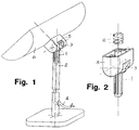
- la FIG. 1 représente une lampe de bureau pourvue d'une articulation en conformité avec l'invention;
- la FIG. 2 représente la vue axonométrique d'ensemble de l'articulation utilisée pour la lampe de la Fig. 1;
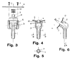
- la FIG. 3 représente, en section verticale, la vue éclatée de l'articulation de la Fig. 2;
- la FIG. 4 représente la vue en coupe verticale de l'articulation de la Fig. 2 avec la parabole ou abat-jour monté;
- la FIG. 5 représente la vue en coupe suivant la ligne D-D de la Fig. 4;
- la FIG. 6 représente la vue en coupe verticale de l'articulation de la Fig. 4 avec la parabole ou abat-jour partiellement incliné par rotation.
- Réduite à sa structure essentielle et en référence aux dessins annexés, une articulation cylindrique à friction pour lampe à tige ou lampadaire, avec porte-lampe ou douille orientable, comprend conformément à l'invention:
- un fuseau central tubulaire 1 à engager à baïonnette dans la tige ou pied 2 de la lampe et à travers lequel passe un câble électrique 4, et avec une tête cylindrique 3 à axe perpendiculaire à celui du fuseau, percée suivant l'axe de celui-ci et ouverte vers le haut pour permettre le passage du câble électrique; la surface extérieure du fuseau 1 présente plusieurs rainures ou cannelures longitudinales pour définir autant d'ailettes flexibles 11 de manière être adaptable à différents diamètres de tige, tout en assurant un montage sûr et permanent;
- un protecteur 5 en forme de boîtier, monté fou sur les extrémités cylindriques de ladite tête 3 et à même de délimiter une cavité ouverte vers le haut;
- un patin 8, inséré dans la cavité du protecteur sur le sommet de la tête du fuseau, avec une base en forme de gouttière semicirculaire, pour appuyer sur l'extrémité cylindrique correspondante de la tête 3, et avec une queue 9 percée axialement pour le passage du câble 4; sur ledit patin est monté un ressort 10 en hélice cylindrique qui est interposé, à force, entre la base du patin et la parabole 6 de la lampe, et maintenu en place au moyen de deux vis 7 insérées dans le protecteur 5. La résistance à la rotation du protecteur 5 par rapport à la tête du fuseau 1 est déterminée par la pression du ressort 10 sur le patin 8.
- Une telle articulation, excepté le ressort 10, est réalisée en matière plastique artificielle résistante à la chaleur en assurant simultanément l'isolation électrique et celle thermique du câble.
- En référence à la Fig. 1 des dessins annexés, l'articulation selon l'invention peut, par exemple, être appliquée à une lampe à pied de bureau, permettant ainsi d'obtenir coûts réduits un produit ayant une esthétique agréable, de grande fiabilité, et avec une amplitude d'orientation supérieure à 120°.
Claims (2)
- Zylindrisches Gelenk für eine Stiellampe oder Stehlampe mit einstellbarem Lampenträger bzw. einstellbarer Lampenfassung, für Möbeltürflügel oder für andere Verwendungen, umfassend eine als zylindrische Wendel ausgebildete Feder (10), welche mit Spannung zwischen der Basis einer Abschlußschale des Gelenkes und dem Parabolschirm einer Lampe bzw. einem anderen beweglichen Element eingespannt ist, dadurch gekennzeichnet, daß sie aus hitzebeständigem Plastikmaterial hergestellt ist und umfaßt:- einen rohrförmigen Schaft (1) für einen Bajonetteingriff in den Stiel oder Fuß (2) der Lampe oder in ein anderes festes Trägerelement, mit einem zylindrischen Kopf (3) mit einer zur Achse des Schaftes (1) rechtwinkeligen Achse, wobei dieser Kopf (3) quer zu seiner eigenen Längsachse durchbohrt und nach oben offen ist, um den Durchtritt eines elektrischen Kabels (4) zu ermöglichen;- eine Schutzkappe (5) in Form eines einen Hohlraum aufweisenden Gehäuses, welche drehbar auf den Enden dieses Kopfes (3) des Schaftes (1) gelagert und an dem Parabolschirm bzw. Lampenträger (6) einer Lampe oder an einem anderen beweglichen Element mittels zweier Befestigungsschrauben (7) befestigt ist; daß die Schale (8) in den Hohlraum der Schutzkappe eingelegt ist; daß die Schale (8) eine Basis in Form einer Halbkreisrinne hat, die auf den Enden des Kopfes (3) aufliegt; daß die Schale (8) einen durchbohrten Fortsatz (9) hat; und daß diese Schale (8) mittels der in die Schutzkappe (5) eingeschraubten Schrauben (7) festgehalten wird.
- Gelenk nach Anspruch 1, dadurch gekennzeichnet, daß die äußere Oberfläche des Schaftes (1) kanneliert ist derart, daß mehrere flexible Flügel (11) gebildet werden.
Applications Claiming Priority (2)
| Application Number | Priority Date | Filing Date | Title |
|---|---|---|---|
| IT8709490A IT8709490A0 (it) | 1987-09-22 | 1987-09-22 | Articolazione cilindrica a frizione |
| IT949087 | 1987-09-22 |
Publications (3)
| Publication Number | Publication Date |
|---|---|
| EP0309420A2 EP0309420A2 (fr) | 1989-03-29 |
| EP0309420A3 EP0309420A3 (en) | 1990-05-23 |
| EP0309420B1 true EP0309420B1 (fr) | 1994-07-06 |
Family
ID=11130908
Family Applications (1)
| Application Number | Title | Priority Date | Filing Date |
|---|---|---|---|
| EP88830368A Expired - Lifetime EP0309420B1 (fr) | 1987-09-22 | 1988-09-14 | Articulation cylindrique |
Country Status (5)
| Country | Link |
|---|---|
| EP (1) | EP0309420B1 (fr) |
| AT (1) | ATE108261T1 (fr) |
| DE (1) | DE3850545T2 (fr) |
| ES (1) | ES2058335T3 (fr) |
| IT (1) | IT8709490A0 (fr) |
Families Citing this family (3)
| Publication number | Priority date | Publication date | Assignee | Title |
|---|---|---|---|---|
| DE19730285A1 (de) * | 1997-07-15 | 1999-02-11 | Joachim Dipl Ing Niehaus | Drehgelenk für ein Traversenprofil |
| DE202005010313U1 (de) * | 2005-06-30 | 2006-11-23 | Ilt Gmbh International Lighting Technologies | Stehleuchte mit Leuchtenkopf |
| DE202017101142U1 (de) * | 2017-03-01 | 2018-06-04 | Zumtobel Lighting Gmbh | Leuchte mit drehbar gelagertem Lichtkopf |
Family Cites Families (6)
| Publication number | Priority date | Publication date | Assignee | Title |
|---|---|---|---|---|
| US3278203A (en) * | 1964-02-05 | 1966-10-11 | Snyder Mfg Company | Swivel connector for lamps and the like |
| GB1438760A (en) * | 1972-06-17 | 1976-06-09 | Temple B | Universal joint |
| DE7838325U1 (de) * | 1978-12-23 | 1980-05-29 | Dornseif & Linde, 5883 Kierspe | Elektrische leuchte, insbesondere strahlerleuchte |
| US4322098A (en) * | 1979-05-11 | 1982-03-30 | I. W. Industries, Inc. | Swivel joint |
| NL8104430A (nl) * | 1981-09-28 | 1983-04-18 | Philips Nv | Verlichtingsarmatuur. |
| DE3603981A1 (de) * | 1986-02-08 | 1986-07-31 | Erich Dipl.-Ing. 8750 Aschaffenburg Hille | Hohlkugelgelenk mit gleitsperre |
-
1987
- 1987-09-22 IT IT8709490A patent/IT8709490A0/it unknown
-
1988
- 1988-09-14 EP EP88830368A patent/EP0309420B1/fr not_active Expired - Lifetime
- 1988-09-14 ES ES88830368T patent/ES2058335T3/es not_active Expired - Lifetime
- 1988-09-14 AT AT88830368T patent/ATE108261T1/de not_active IP Right Cessation
- 1988-09-14 DE DE3850545T patent/DE3850545T2/de not_active Expired - Fee Related
Also Published As
| Publication number | Publication date |
|---|---|
| IT8709490A0 (it) | 1987-09-22 |
| EP0309420A2 (fr) | 1989-03-29 |
| ES2058335T3 (es) | 1994-11-01 |
| DE3850545D1 (de) | 1994-08-11 |
| EP0309420A3 (en) | 1990-05-23 |
| DE3850545T2 (de) | 1995-02-23 |
| ATE108261T1 (de) | 1994-07-15 |
Similar Documents
| Publication | Publication Date | Title |
|---|---|---|
| EP0051022A1 (fr) | Charnière de lunettes | |
| FR2699595A1 (fr) | Dispositif de guidage en rotation d'un anneau de commande d'aubes pivotantes. | |
| FR2828247A1 (fr) | Structure de verrouillage d'elements en forme de tige a hauteur reglable | |
| EP0417265B1 (fr) | Appareil de traitement d'informations portatif a ecran orientable | |
| FR2620793A1 (fr) | Phare pour automobile a miroir reflechissant basculant | |
| FR2620794A1 (fr) | Phare pour automobile a miroir reflechissant basculant | |
| FR2516363A1 (fr) | Canne, notamment pour personnes affaiblies | |
| EP0309420B1 (fr) | Articulation cylindrique | |
| FR2601435A1 (fr) | Pied en particulier pour terminaux d'affichage | |
| FR2764623A1 (fr) | Dispositif de jonction pour main courante | |
| WO1997046790A1 (fr) | Carottier | |
| FR2705710A3 (fr) | Mur-rideau et ensemble pour son montage. | |
| EP0785332B1 (fr) | Disposif de positionnement angulaire d'une masse par rapport à un axe horizontal de support et appareil d'éclairage équipé d'un tel dispositif | |
| CH678611A5 (fr) | ||
| FR2794575A1 (fr) | Bougie d'allumage pour moteur a combustion interne | |
| EP0521806B1 (fr) | Outil motorisé portatif utilisable à deux mains, en particulier taille-haies | |
| CA2105312A1 (fr) | Dispositif de couplage mecanique et electrique pour une installation a tres basse tension | |
| FR2712377A1 (fr) | Support d'éclairage orientable à connecter dans des panneaux conducteurs multifeuilles. | |
| FR2665513A1 (fr) | Dispositif d'eclairage retractable. | |
| FR2677574A1 (fr) | Dispositif de decoupe a fil chaud. | |
| EP0935093A1 (fr) | Appareil d'éclairage étanche | |
| EP0378975B1 (fr) | Moyens de fixation de la base et de l'articulation du projecteur au montant tubulaire correspondant des lampes, en particulier des lampes de bureau et lampadaires | |
| FR2642695A1 (fr) | Manche pour outil | |
| FR2791123A1 (fr) | Abat-jour reglable et lampe equipee d'un tel abat-jour | |
| FR2600462A1 (fr) | Dispositif de connexion permettant, a volonte, la rotation a 360o, sans torsion des conducteurs electriques |
Legal Events
| Date | Code | Title | Description |
|---|---|---|---|
| PUAI | Public reference made under article 153(3) epc to a published international application that has entered the european phase |
Free format text: ORIGINAL CODE: 0009012 |
|
| AK | Designated contracting states |
Kind code of ref document: A2 Designated state(s): AT BE CH DE ES FR GB GR IT LI LU NL SE |
|
| PUAL | Search report despatched |
Free format text: ORIGINAL CODE: 0009013 |
|
| AK | Designated contracting states |
Kind code of ref document: A3 Designated state(s): AT BE CH DE ES FR GB GR IT LI LU NL SE |
|
| RHK1 | Main classification (correction) |
Ipc: F21V 21/28 |
|
| 17P | Request for examination filed |
Effective date: 19900731 |
|
| 17Q | First examination report despatched |
Effective date: 19930302 |
|
| GRAA | (expected) grant |
Free format text: ORIGINAL CODE: 0009210 |
|
| AK | Designated contracting states |
Kind code of ref document: B1 Designated state(s): AT BE CH DE ES FR GB GR IT LI LU NL SE |
|
| PG25 | Lapsed in a contracting state [announced via postgrant information from national office to epo] |
Ref country code: NL Effective date: 19940706 Ref country code: GR Free format text: LAPSE BECAUSE OF FAILURE TO SUBMIT A TRANSLATION OF THE DESCRIPTION OR TO PAY THE FEE WITHIN THE PRESCRIBED TIME-LIMIT Effective date: 19940706 Ref country code: FR Effective date: 19940706 Ref country code: AT Effective date: 19940706 |
|
| REF | Corresponds to: |
Ref document number: 108261 Country of ref document: AT Date of ref document: 19940715 Kind code of ref document: T |
|
| REF | Corresponds to: |
Ref document number: 3850545 Country of ref document: DE Date of ref document: 19940811 |
|
| ITF | It: translation for a ep patent filed |
Owner name: ING. DR. LAZZARO MARTINI S.R.L. |
|
| PG25 | Lapsed in a contracting state [announced via postgrant information from national office to epo] |
Ref country code: LU Free format text: LAPSE BECAUSE OF NON-PAYMENT OF DUE FEES Effective date: 19940930 Ref country code: LI Effective date: 19940930 Ref country code: CH Effective date: 19940930 Ref country code: BE Effective date: 19940930 |
|
| PG25 | Lapsed in a contracting state [announced via postgrant information from national office to epo] |
Ref country code: SE Effective date: 19941006 Ref country code: GB Effective date: 19941006 |
|
| REG | Reference to a national code |
Ref country code: ES Ref legal event code: FG2A Ref document number: 2058335 Country of ref document: ES Kind code of ref document: T3 |
|
| EN | Fr: translation not filed | ||
| NLV1 | Nl: lapsed or annulled due to failure to fulfill the requirements of art. 29p and 29m of the patents act | ||
| PLBE | No opposition filed within time limit |
Free format text: ORIGINAL CODE: 0009261 |
|
| STAA | Information on the status of an ep patent application or granted ep patent |
Free format text: STATUS: NO OPPOSITION FILED WITHIN TIME LIMIT |
|
| GBPC | Gb: european patent ceased through non-payment of renewal fee |
Effective date: 19941006 |
|
| REG | Reference to a national code |
Ref country code: CH Ref legal event code: PL |
|
| 26N | No opposition filed | ||
| BERE | Be: lapsed |
Owner name: PEISA S.R.L. Effective date: 19950930 |
|
| REG | Reference to a national code |
Ref country code: ES Ref legal event code: PC2A |
|
| PGFP | Annual fee paid to national office [announced via postgrant information from national office to epo] |
Ref country code: ES Payment date: 20020930 Year of fee payment: 15 |
|
| PGFP | Annual fee paid to national office [announced via postgrant information from national office to epo] |
Ref country code: DE Payment date: 20021130 Year of fee payment: 15 |
|
| PG25 | Lapsed in a contracting state [announced via postgrant information from national office to epo] |
Ref country code: ES Free format text: LAPSE BECAUSE OF NON-PAYMENT OF DUE FEES Effective date: 20030915 |
|
| PG25 | Lapsed in a contracting state [announced via postgrant information from national office to epo] |
Ref country code: DE Free format text: LAPSE BECAUSE OF NON-PAYMENT OF DUE FEES Effective date: 20040401 |
|
| REG | Reference to a national code |
Ref country code: ES Ref legal event code: FD2A Effective date: 20030915 |
|
| PG25 | Lapsed in a contracting state [announced via postgrant information from national office to epo] |
Ref country code: IT Free format text: LAPSE BECAUSE OF NON-PAYMENT OF DUE FEES;WARNING: LAPSES OF ITALIAN PATENTS WITH EFFECTIVE DATE BEFORE 2007 MAY HAVE OCCURRED AT ANY TIME BEFORE 2007. THE CORRECT EFFECTIVE DATE MAY BE DIFFERENT FROM THE ONE RECORDED. Effective date: 20050914 |