EP0309304B1 - Capteur de position électrique et/ou électronique - Google Patents
Capteur de position électrique et/ou électronique Download PDFInfo
- Publication number
- EP0309304B1 EP0309304B1 EP88402179A EP88402179A EP0309304B1 EP 0309304 B1 EP0309304 B1 EP 0309304B1 EP 88402179 A EP88402179 A EP 88402179A EP 88402179 A EP88402179 A EP 88402179A EP 0309304 B1 EP0309304 B1 EP 0309304B1
- Authority
- EP
- European Patent Office
- Prior art keywords
- clamping ring
- sensor
- detecting element
- respect
- casing
- Prior art date
- Legal status (The legal status is an assumption and is not a legal conclusion. Google has not performed a legal analysis and makes no representation as to the accuracy of the status listed.)
- Expired - Lifetime
Links
- 238000012544 monitoring process Methods 0.000 claims description 3
- 239000012777 electrically insulating material Substances 0.000 claims 1
- 239000012858 resilient material Substances 0.000 claims 1
- 239000004020 conductor Substances 0.000 abstract description 12
- 238000001514 detection method Methods 0.000 description 4
- 238000009434 installation Methods 0.000 description 4
- 235000014676 Phragmites communis Nutrition 0.000 description 2
- 230000002950 deficient Effects 0.000 description 2
- 239000011810 insulating material Substances 0.000 description 2
- 238000012423 maintenance Methods 0.000 description 2
- 230000005355 Hall effect Effects 0.000 description 1
- 238000006073 displacement reaction Methods 0.000 description 1
- 239000012530 fluid Substances 0.000 description 1
- 238000003754 machining Methods 0.000 description 1
- 230000003287 optical effect Effects 0.000 description 1
- 210000000056 organ Anatomy 0.000 description 1
- 230000001681 protective effect Effects 0.000 description 1
- 230000035939 shock Effects 0.000 description 1
Images
Classifications
-
- F—MECHANICAL ENGINEERING; LIGHTING; HEATING; WEAPONS; BLASTING
- F15—FLUID-PRESSURE ACTUATORS; HYDRAULICS OR PNEUMATICS IN GENERAL
- F15B—SYSTEMS ACTING BY MEANS OF FLUIDS IN GENERAL; FLUID-PRESSURE ACTUATORS, e.g. SERVOMOTORS; DETAILS OF FLUID-PRESSURE SYSTEMS, NOT OTHERWISE PROVIDED FOR
- F15B15/00—Fluid-actuated devices for displacing a member from one position to another; Gearing associated therewith
- F15B15/20—Other details, e.g. assembly with regulating devices
- F15B15/28—Means for indicating the position, e.g. end of stroke
- F15B15/2892—Means for indicating the position, e.g. end of stroke characterised by the attachment means
-
- G—PHYSICS
- G01—MEASURING; TESTING
- G01D—MEASURING NOT SPECIALLY ADAPTED FOR A SPECIFIC VARIABLE; ARRANGEMENTS FOR MEASURING TWO OR MORE VARIABLES NOT COVERED IN A SINGLE OTHER SUBCLASS; TARIFF METERING APPARATUS; MEASURING OR TESTING NOT OTHERWISE PROVIDED FOR
- G01D11/00—Component parts of measuring arrangements not specially adapted for a specific variable
- G01D11/30—Supports specially adapted for an instrument; Supports specially adapted for a set of instruments
-
- Y—GENERAL TAGGING OF NEW TECHNOLOGICAL DEVELOPMENTS; GENERAL TAGGING OF CROSS-SECTIONAL TECHNOLOGIES SPANNING OVER SEVERAL SECTIONS OF THE IPC; TECHNICAL SUBJECTS COVERED BY FORMER USPC CROSS-REFERENCE ART COLLECTIONS [XRACs] AND DIGESTS
- Y10—TECHNICAL SUBJECTS COVERED BY FORMER USPC
- Y10S—TECHNICAL SUBJECTS COVERED BY FORMER USPC CROSS-REFERENCE ART COLLECTIONS [XRACs] AND DIGESTS
- Y10S91/00—Motors: expansible chamber type
- Y10S91/04—Magnets
Definitions
- the present invention relates to an electrical and / or electronic sensor or detector for a mobile element whose position is to be identified with respect to a fixed element or station, this sensor comprising means for fixing to the element or the fixed station a detector element adapted projecting from these fixing means, a member for connecting the detector element to the fixing means, and at least one connection conductor intended to connect the detector element to a monitoring system.
- Sequence control systems use numerous sensors or position detectors which make it possible to identify the completion of a sequence, such as the stroke of the piston of a jack. Adjusting the position of these detectors relative to the movable members whose movement they control, as well as keeping their detection elements, themselves relatively fragile, generally entail higher costs than those corresponding to the mobile organ proper. Whenever one of these detectors fails, it is indeed necessary not only to exchange it, which requires to wire and rewire the conductors, but most often to a new adjustment of its position and its fixing which often reveal awkward.
- the present invention proposes to facilitate the positioning and the adjustment of the position of sensors such as position detectors, while allowing easy exchange of the sensor element itself.
- GB-A-2 180 914 discloses a cylinder piston assembly in which the cylinder tube is provided with guide rails on each of which can slide a mounting part carrying a detector element.
- the guide rail is partially surrounded by the mounting piece between a first side wall and an elastic tongue on which one or more pinching screws can come to rest in order to lock the mounting piece and therefore the detector element in position on the cylinder body.
- the detector element constituted by a proximity switch is removable on the mounting part where it is mounted in front projection to locate the magnetic image of the mobile piston in the cylinder.
- the device proposed in GB-A-2 180 914 requires that the cylinder tube of the jack is equipped with at least one longitudinal rail allowing the fixing of the mounting part or that the jack is provided with longitudinal tie rods allowing the same function of mounting of the detector element mounting piece.
- the present invention proposes to produce a sensor which can be fixed easily, precisely and very firmly, on the external cylinder of a jack provided with a smooth cylindrical external surface without any projecting fixing surface such as a pulling.
- the fixing means are constituted by an annular, one-piece clamp with a casing which contains the electrical connection between the conductor and the detector element and is made of an electric and elastic insulating material
- the annular clamping collar is provided with two elastic extensions which are capable of approaching one towards the other in cooperation with clamping means, the detector element being arranged in lateral overhang relative to the median plane of the collar, so that the axis of vision of the detector element can be positioned firmly in front of a part of the element or of the fixed station which is located outside the area covered by the clamp and the conductor connection is connected to the casing, substantially tangentially to the circle of the clamp, in order to avoid any axial traction or axial engagement of the conductor eur connection, relative to the collar or respectively to the movable member.
- the installation of the sensor on a cylinder with a smooth external surface thus only requires the tightening of the collar without any machining operation and without any attached fixing part.
- By performing a pre-tightening of the collar after a first rough positioning of the sensor it is possible to overcome the friction of the collar, on the envelope where it is tightened, by light pushes or shocks to ensure the positioning of the sensor, controlled for example as a function of the electrical and / or electronic results obtained after its installation.
- the fixing of the sensor and its positioning are thus carried out definitively for a sensor element which is itself perfectly removable.
- the electrical connection envelope between the connection conductor and the connection member forms a block with several faces and projecting from the external surface of the clamp and the conductor connection is connected to the envelope on the side of the clamping means and offset from these clamping means, so as not to impede access to the clamping means placed on the side of said conductor.
- the pins and / or the terminals of the connection member are oriented perpendicular to a face of the envelope substantially parallel to the median plane of the collar, so that said pins or terminals are substantially parallel to the median axis of this collar.
- the envelope may be closed, after the detector element has been put in place, by a cover which carries at least one transparent window for viewing a light indicator from the sensor.
- One of the outer faces of the envelope may carry signs for locating the detection device or locations for the placement of such signs.
- the annular clamping collar is mounted tightly on the external surface of the cylindrical body of the cylinder, orienting the connection conductor (s) tangentially with respect to the cross section of the jack body and by placing the active part of the detector element in lateral overhang opposite a point to be located on the movable member, by rotation of the clamp and axial sliding thereof on the outer surface of the cylinder body, so as to target with this active part of the cylinder body located out of contact with the clamp.
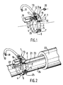
- the support of a sensor 1 has the general shape of a one-piece annular collar 2 with two elastic branches 3 and 4 closing towards each other, at their free end, by the intermediate of an extension 5, 6.
- the extensions 5, 6 are provided respectively with a bore 7 and a sunken nut (not visible in perspective views).
- the clamp 2 made of relatively elastic electrical insulating material, preferably plastic, is surmounted by a block 8 with several faces, integral with it. On one of the side faces 9 of the insulated monoblock 8 leaves, substantially tangentially with respect to the outer circle of the collar 2, an insulated wire 10 with several connection conductors 11 to a monitoring circuit supplied by the sensor 1 and not shown .
- connection terminals preferably female
- the connection terminals 17 male pins
- the detector element 16 mounted on the insulated block 8 this connection member making it possible to connect the output wires 11 to the detector element 16 outside.
- the most commonly used detector elements 16 are Hall effect detectors or flexible reed detectors (also called Reed detectors) 25 to 29 mm in length and capable of working in a wide temperature range (for example from -40 to +150 ° C). These low power consumption detectors are perfectly interchangeable and are fitted with screwed or long-pin connectors for this, guaranteeing the precision and fidelity of their attachment to the insulated block 8.
- the positioning and operation of the sensor device 1 which has just been described will now be explained with reference to FIG. 2. It is proposed, for example, to detect the output of a movable bar 21 actuated by a jack 22 whose the rod is not shown (and can constitute the movable bar itself).
- the movable bar 21 which includes an element for exciting the sensor, generally consisting of a magnet, is surrounded by an envelope formed by protective plates 23 and 24.
- connection member 13, 14, 15, 17 and the elastic branches 3 and 4 are opened so that they engage in an annular collar on the plates 23 and 24 by surrounding them. Then proceed to a prior tightening of the collar 2 on these plates 23 and 24 using a clamping screw 25 which passes through the bore 7 of the extension 5 and is screwed into the nut (not shown) which is embedded in the extension 6.
- the collar 2 is definitively tightened using the screw 25 and the insulated block 8 detector support thus remains in place firmly and will remain so when a defective detector element 16 is subsequently exchanged.
- the sensor device 1 can, for example, be applied advantageously to the detection of the arrival at the end of the stroke of the piston or of the piston rod of a cylinder, such as a pneumatic cylinder.
- the annular collar 2 is then simply tightened on the outside of the cylindrical body of the jack by orienting the insulated wire 10 tangentially with respect to the cross section of the jack body.
- the connection member 13, 14, 15 and 17 is automatically oriented parallel to the axis of the jack to place the interchangeable detector element 16 parallel to the axis of the jack and therefore according to the direction of movement of the piston or of the rod. piston.
- the active beam or the viewing axis 27 of the sensor element 16 is brought into position by axial sliding of the collar 2 on the cylinder body, the position of the collar 2 in rotation being generally indifferent and determined solely by the starting facilities for the insulated wire 10.
- the insulated block 8 remains in a fixed position to allow easy change of the sensor element 16 into in the event of failure thereof, without having to make any new adjustment to the position of the collar 2.
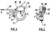
- the parts of the sensor 1 identical to those of Figures 1 and 2 have the same reference marks as in Figures 1 and 2.
- the clamp 2 here also forms a single piece with the multi-sided upper unit, but the latter is produced before equipping the sensor in the form of a hollow element or casing 28 which surmounts the collar 2 and a part 29 of which is placed in cantilever laterally with respect to the collar 2. From this part 29 of the envelope leaves a tip 30 for outputting the insulated wire 10 which can thus exit from the side of the screw 25 without impeding access to the head of this screw to ensure its screwing in the nut 31 embedded in the extension 6.
- the detector element When mounting the sensor according to FIGS. 3 and 4, the detector element itself, not shown in FIGS. 3 and 4 and which forms a block similar to the interchangeable element 16 and connected to an insulated wire 10, is pushed inside the casing 28 to be put in place there after introduction of the wire 10 through the opening of the end piece 30. After the detector element has been placed in the casing 28, the latter is closed by a cover 32 which carries at least one transparent window 33 for viewing a light indicator (not shown) of the sensor.
- the viewing axis 27 of the detector element can be on the median plane of the collar 2 or, as shown in FIG. 4, on the median plane of the door part 29 - side overhang. Thanks to this last mode of embodiment, it is possible to tighten the collar 2 on the accessible part of the body of a jack while placing the viewing axis 27 of the sensor element in front of a part relatively inaccessible to the mounting of this jack body.
- the sensors according to the invention have simple and aesthetic forms while ensuring a significant saving, both with regard to installation costs, as well as maintenance and spare parts management costs, since it is no longer necessary to for the maintenance of a fleet of cylinders fitted with sensors, have a whole stock of special tie rods supporting the sensors.
Landscapes
- Physics & Mathematics (AREA)
- Engineering & Computer Science (AREA)
- Fluid Mechanics (AREA)
- Mechanical Engineering (AREA)
- General Engineering & Computer Science (AREA)
- General Physics & Mathematics (AREA)
- Measurement Of Length, Angles, Or The Like Using Electric Or Magnetic Means (AREA)
- Measurement Of Radiation (AREA)
- Measuring Fluid Pressure (AREA)
- Clamps And Clips (AREA)
- Actuator (AREA)
- Character Spaces And Line Spaces In Printers (AREA)
- Switches That Are Operated By Magnetic Or Electric Fields (AREA)
- Measuring Pulse, Heart Rate, Blood Pressure Or Blood Flow (AREA)
- Electrical Discharge Machining, Electrochemical Machining, And Combined Machining (AREA)
- Control Of Motors That Do Not Use Commutators (AREA)
- Discharging, Photosensitive Material Shape In Electrophotography (AREA)
Priority Applications (1)
| Application Number | Priority Date | Filing Date | Title |
|---|---|---|---|
| AT88402179T ATE72699T1 (de) | 1987-09-16 | 1988-08-30 | Elektrischer/elektronischer positionsgeber. |
Applications Claiming Priority (2)
| Application Number | Priority Date | Filing Date | Title |
|---|---|---|---|
| FR8712806A FR2620530B1 (fr) | 1987-09-16 | 1987-09-16 | Dispositif de capteur a effet electrique |
| FR8712806 | 1987-09-16 |
Publications (2)
| Publication Number | Publication Date |
|---|---|
| EP0309304A1 EP0309304A1 (fr) | 1989-03-29 |
| EP0309304B1 true EP0309304B1 (fr) | 1992-02-19 |
Family
ID=9354939
Family Applications (1)
| Application Number | Title | Priority Date | Filing Date |
|---|---|---|---|
| EP88402179A Expired - Lifetime EP0309304B1 (fr) | 1987-09-16 | 1988-08-30 | Capteur de position électrique et/ou électronique |
Country Status (8)
| Country | Link |
|---|---|
| US (1) | US4898079A (https=) |
| EP (1) | EP0309304B1 (https=) |
| AT (1) | ATE72699T1 (https=) |
| CA (1) | CA1323082C (https=) |
| DE (1) | DE3868472D1 (https=) |
| ES (1) | ES2008664T3 (https=) |
| FR (1) | FR2620530B1 (https=) |
| GR (2) | GR890300097T1 (https=) |
Families Citing this family (23)
| Publication number | Priority date | Publication date | Assignee | Title |
|---|---|---|---|---|
| SE463684B (sv) * | 1989-12-22 | 1991-01-07 | Mecman Ab | Haallaranordning foer kolvlaegesavkaennare |
| US5103170A (en) * | 1990-05-21 | 1992-04-07 | The Torrington Company | Antifriction bearing with a clip-on sensor |
| DE9010114U1 (de) * | 1990-07-03 | 1990-09-06 | Festo KG, 7300 Esslingen | Arbeitszylinder |
| US5455509A (en) * | 1990-10-26 | 1995-10-03 | Kabushiki Kaisha Komatsu Seisakusho | Device for mounting position detecting sensor |
| US5180978A (en) * | 1991-12-02 | 1993-01-19 | Honeywell Inc. | Proximity sensor with reduced temperature sensitivity using A.C. and D.C. energy |
| DE9305896U1 (de) * | 1993-04-20 | 1993-06-17 | Soyck, Gerno, 5884 Halver | Magnetfeldsensor für zugankerlose Arbeitszylinder |
| CH690250A5 (de) * | 1994-06-30 | 2000-06-15 | Siemens Building Tech Ag | Messfühler zur einfachen Befestigung an einem Rohr. |
| IT240544Y1 (it) * | 1996-03-25 | 2001-04-02 | Ciar Srl | Attuatore lineare con microinterruttori di fine corsa ad elevatasemplicita'di regolazione. |
| US6447240B1 (en) | 1997-12-04 | 2002-09-10 | Trimble Navigation Limited | Arrangement for determining the relative angular orientation between a first machine element and a second machine element |
| US6099235A (en) * | 1997-12-04 | 2000-08-08 | Spectra Precision, Inc. | Arrangement for determining the relative angular orientation between a first machine element and a second machine element |
| US6325590B1 (en) | 1997-12-04 | 2001-12-04 | Spectra Precision, Inc. | Arrangement for determining the relative angular orientation between a first machine element and a second machine element |
| DE19902781A1 (de) * | 1999-01-25 | 2000-08-10 | Ettemeyer Gmbh & Co Mes Und Pr | Meßkopfhalterung |
| DE29905700U1 (de) | 1999-03-27 | 1999-06-24 | Festo AG & Co, 73734 Esslingen | Sensoranordnung |
| IT1308474B1 (it) * | 1999-05-07 | 2001-12-17 | Cogip Srl | Interfaccia di collegamento per sensori di posizione per organimeccanici mobili, quali cilindri pneumatici, idraulici e simili, e |
| US6473189B1 (en) | 1999-08-09 | 2002-10-29 | Caterpillar Inc | Apparatus and method for determining a distance to a reflective surface |
| US6725761B1 (en) | 2002-09-30 | 2004-04-27 | Prince Manufacturing Corporation | Spooling device assembly for hydraulic cylinder and method of assembling same |
| BRPI1001408B1 (pt) * | 2010-03-08 | 2019-06-25 | Sabo Industria E Comercio De Autopeças S/A | Conjunto roda emissora |
| JP5382591B2 (ja) * | 2010-12-21 | 2014-01-08 | Smc株式会社 | 流体圧シリンダの位置検出装置 |
| FR2977389B1 (fr) * | 2011-06-29 | 2015-07-17 | Legrand France | Prise electrique munie de moyens d'identification, fiche electrique et ensemble electrique associes. |
| FR2977390B1 (fr) * | 2011-06-29 | 2013-10-11 | Legrand France | Fiche electrique et ensemble electrique associe. |
| JP5914929B2 (ja) * | 2011-09-12 | 2016-05-11 | Smc株式会社 | 位置センサ用取付バンド |
| FR3006119B1 (fr) * | 2013-05-22 | 2015-05-29 | Legrand France | Appareillage electrique comportant un capteur de temperature loge dans un element de support |
| ES1257574Y (es) * | 2020-08-26 | 2021-02-26 | Cebi Electromechanical Components Spain S A | Sistema de fijacion de un sensor de posicion |
Family Cites Families (14)
| Publication number | Priority date | Publication date | Assignee | Title |
|---|---|---|---|---|
| US3017621A (en) * | 1956-12-31 | 1962-01-16 | Martin Marietta Corp | Proximity limit position detector |
| DE6947597U (de) * | 1969-12-09 | 1971-05-13 | Bosch Gmbh Robert | Spannband. |
| US4071725A (en) * | 1976-02-27 | 1978-01-31 | Ibec Industries, Inc. | Proximity switch for fluid cylinders |
| US4086456A (en) * | 1976-10-04 | 1978-04-25 | Cincinnati Milacron Inc. | Mounting for magnetic switch |
| US4230023A (en) * | 1977-12-05 | 1980-10-28 | Scovill Manufacturing Company | Clamping apparatus |
| SE430531B (sv) * | 1980-07-10 | 1983-11-21 | Atlas Copco Ab | Tryckfluidumdriven cylinderanordning med endlegesindikering |
| JPS57195907A (en) * | 1981-05-26 | 1982-12-01 | Inoue Denshi Kk | Fluid pressure cylinder |
| DE3241237C2 (de) * | 1982-11-09 | 1985-10-24 | Gewerkschaft Eisenhütte Westfalia, 4670 Lünen | Schubkolbengetriebe, insbesondere zur Verwendung als Rückzylinder in Bergbau-Gewinnungsbetrieben, mit an der Kolbenstange angeordnetem Dauermagnetsystem |
| US4594487A (en) * | 1984-12-07 | 1986-06-10 | Galland Henning Nopak, Inc. | Mounting means for proximity sensing device |
| JPS61180109A (ja) * | 1985-02-05 | 1986-08-12 | Nippon Soken Inc | 変位センサ |
| DE3609537A1 (de) * | 1985-06-29 | 1987-01-08 | Wabco Westinghouse Steuerung | Beruehrungslos arbeitende naeherungsschalteinrichtung |
| DE3533955A1 (de) * | 1985-09-24 | 1987-03-26 | Festo Kg | Kolben-zylinder-anordnung |
| DE8626017U1 (de) * | 1986-09-30 | 1986-11-20 | Werner Turck GmbH & Co. KG, 58553 Halver | Näherungsschalter mit einem in einen Druckzylinder einbaubaren Sensorteil zur Erfassung der Kolbenstellung |
| US4752657A (en) * | 1987-05-07 | 1988-06-21 | Allied Automation Systems, Inc. | Proximity switch mounting apparatus |
-
1987
- 1987-09-16 FR FR8712806A patent/FR2620530B1/fr not_active Expired - Fee Related
-
1988
- 1988-08-30 DE DE8888402179T patent/DE3868472D1/de not_active Expired - Fee Related
- 1988-08-30 AT AT88402179T patent/ATE72699T1/de not_active IP Right Cessation
- 1988-08-30 ES ES198888402179T patent/ES2008664T3/es not_active Expired - Lifetime
- 1988-08-30 EP EP88402179A patent/EP0309304B1/fr not_active Expired - Lifetime
- 1988-09-13 CA CA000577201A patent/CA1323082C/en not_active Expired - Fee Related
- 1988-09-14 US US07/244,179 patent/US4898079A/en not_active Expired - Fee Related
-
1989
- 1989-10-31 GR GR89300097T patent/GR890300097T1/el unknown
-
1992
- 1992-02-20 GR GR910400425T patent/GR3003844T3/el unknown
Also Published As
| Publication number | Publication date |
|---|---|
| CA1323082C (en) | 1993-10-12 |
| GR3003844T3 (https=) | 1993-03-16 |
| ES2008664T3 (es) | 1992-11-16 |
| DE3868472D1 (de) | 1992-03-26 |
| ES2008664A4 (es) | 1989-08-01 |
| GR890300097T1 (en) | 1989-10-31 |
| FR2620530A1 (fr) | 1989-03-17 |
| US4898079A (en) | 1990-02-06 |
| EP0309304A1 (fr) | 1989-03-29 |
| ATE72699T1 (de) | 1992-03-15 |
| FR2620530B1 (fr) | 1991-04-12 |
Similar Documents
| Publication | Publication Date | Title |
|---|---|---|
| EP0309304B1 (fr) | Capteur de position électrique et/ou électronique | |
| EP3320585B1 (fr) | Ensemble de prise électrique avec solution de déconnexion électrique | |
| EP2887076B1 (fr) | Capteur de courant à boucle de Rogowski et procédé de fabrication d'un tel capteur de courant | |
| EP1744163B1 (fr) | Tachymètre pour roue d'aéronef | |
| EP0061124A1 (fr) | Dispositif suiveur de pas de rainures hélicoidales | |
| FR2535070A1 (fr) | Charniere a ressort pour monture de lunettes | |
| FR2748987A1 (fr) | Systeme de blocage temporaire de deplacement de deux corps l'un par rapport a l'autre, suivant au moins un sens d'une direction predeterminee | |
| EP3109878B1 (fr) | Ampoule à vide et appareillage de protection électrique comportant une telle ampoule | |
| FR3022984A1 (fr) | Dispositif de reglage de l'inclinaison d'un reflecteur | |
| FR2577633A1 (fr) | Commande mecanique par cable a dispositif de reglage automatique et detecteur electrique de mise en oeuvre | |
| FR2525716A1 (fr) | Procede de surveillance de l'etat d'usure de garnitures de frein a disque, indicateur d'etat d'usure et frein a disque | |
| EP0192309A1 (fr) | Appareil d'observation mixte jour-nuit | |
| FR2794236A1 (fr) | Dispositif permettant de connaitre la position et de mesurer les deplacements du piston ou de la tige de piston dans la chambre d'un verin du type comprenant un capteur potentiometrique rectiligne lineaire | |
| BE898177A (fr) | Dispositif pour piston de poussée, destiné à etre en particulier utilisé en tant que vérin de ripage dans des installations d'abattage minières, comprenant un système à aimants permanents disposé sur la tige du piston. | |
| CH681488A5 (https=) | ||
| FR2679474A1 (fr) | Appareil pour optimiser la perpendicularite d'un outil par rapport a la surface de la piece, lors d'un percage. | |
| EP1426748B1 (fr) | Capteur haute température et procédé d'assemblage de celui-ci | |
| FR2699334A1 (fr) | Dispositif de codage indexable, et dispositif de connexion le comprenant. | |
| EP0959362B1 (fr) | Dispositif de mesure d'une grandeur physique liée à la rotation d'un organe | |
| EP0824196B1 (fr) | Tête de commande électro-pneumatique pour actuateurs | |
| EP0958984B1 (fr) | Bougie de véhicule ferroviaire | |
| FR2915001A1 (fr) | Procede et dispositif a deux lasers pour la detection de systemes optiques grossissants. | |
| EP3264431B1 (fr) | Electro-aimant linéaire bistable | |
| FR3044835A1 (fr) | Systeme de maintien, ensemble de capteur uhf et poste electrique a haute tension | |
| FR2864222A1 (fr) | Dispositif permettant de connaitre la position et de mesurer le deplacement du piston ou de la tige de piston dans la chambre d'un verin |
Legal Events
| Date | Code | Title | Description |
|---|---|---|---|
| PUAI | Public reference made under article 153(3) epc to a published international application that has entered the european phase |
Free format text: ORIGINAL CODE: 0009012 |
|
| AK | Designated contracting states |
Kind code of ref document: A1 Designated state(s): AT BE CH DE ES FR GB GR IT LI LU NL SE |
|
| TCAT | At: translation of patent claims filed | ||
| TCNL | Nl: translation of patent claims filed | ||
| GBC | Gb: translation of claims filed (gb section 78(7)/1977) | ||
| ITCL | It: translation for ep claims filed |
Representative=s name: MARCHI E MITTLER |
|
| 17P | Request for examination filed |
Effective date: 19890826 |
|
| 17Q | First examination report despatched |
Effective date: 19891114 |
|
| ITF | It: translation for a ep patent filed | ||
| GRAA | (expected) grant |
Free format text: ORIGINAL CODE: 0009210 |
|
| AK | Designated contracting states |
Kind code of ref document: B1 Designated state(s): AT BE CH DE ES FR GB GR IT LI LU NL SE |
|
| REF | Corresponds to: |
Ref document number: 72699 Country of ref document: AT Date of ref document: 19920315 Kind code of ref document: T |
|
| GBT | Gb: translation of ep patent filed (gb section 77(6)(a)/1977) | ||
| REF | Corresponds to: |
Ref document number: 3868472 Country of ref document: DE Date of ref document: 19920326 |
|
| REG | Reference to a national code |
Ref country code: ES Ref legal event code: FG2A Ref document number: 2008664 Country of ref document: ES Kind code of ref document: T3 |
|
| REG | Reference to a national code |
Ref country code: GR Ref legal event code: FG4A Free format text: 3003844 |
|
| PLBE | No opposition filed within time limit |
Free format text: ORIGINAL CODE: 0009261 |
|
| STAA | Information on the status of an ep patent application or granted ep patent |
Free format text: STATUS: NO OPPOSITION FILED WITHIN TIME LIMIT |
|
| 26N | No opposition filed | ||
| EPTA | Lu: last paid annual fee | ||
| EAL | Se: european patent in force in sweden |
Ref document number: 88402179.1 |
|
| PGFP | Annual fee paid to national office [announced via postgrant information from national office to epo] |
Ref country code: FR Payment date: 19950502 Year of fee payment: 8 |
|
| PGFP | Annual fee paid to national office [announced via postgrant information from national office to epo] |
Ref country code: BE Payment date: 19950505 Year of fee payment: 8 |
|
| PGFP | Annual fee paid to national office [announced via postgrant information from national office to epo] |
Ref country code: GR Payment date: 19950531 Year of fee payment: 8 |
|
| PGFP | Annual fee paid to national office [announced via postgrant information from national office to epo] |
Ref country code: LU Payment date: 19950601 Year of fee payment: 8 |
|
| PGFP | Annual fee paid to national office [announced via postgrant information from national office to epo] |
Ref country code: SE Payment date: 19950612 Year of fee payment: 8 |
|
| PGFP | Annual fee paid to national office [announced via postgrant information from national office to epo] |
Ref country code: ES Payment date: 19950720 Year of fee payment: 8 |
|
| PGFP | Annual fee paid to national office [announced via postgrant information from national office to epo] |
Ref country code: GB Payment date: 19950803 Year of fee payment: 8 |
|
| PGFP | Annual fee paid to national office [announced via postgrant information from national office to epo] |
Ref country code: NL Payment date: 19950830 Year of fee payment: 8 |
|
| PGFP | Annual fee paid to national office [announced via postgrant information from national office to epo] |
Ref country code: AT Payment date: 19950831 Year of fee payment: 8 |
|
| PGFP | Annual fee paid to national office [announced via postgrant information from national office to epo] |
Ref country code: DE Payment date: 19951028 Year of fee payment: 8 |
|
| PGFP | Annual fee paid to national office [announced via postgrant information from national office to epo] |
Ref country code: CH Payment date: 19951124 Year of fee payment: 8 |
|
| PG25 | Lapsed in a contracting state [announced via postgrant information from national office to epo] |
Ref country code: LU Free format text: LAPSE BECAUSE OF NON-PAYMENT OF DUE FEES Effective date: 19960830 Ref country code: GB Effective date: 19960830 Ref country code: AT Effective date: 19960830 |
|
| PG25 | Lapsed in a contracting state [announced via postgrant information from national office to epo] |
Ref country code: SE Effective date: 19960831 Ref country code: LI Effective date: 19960831 Ref country code: ES Free format text: LAPSE BECAUSE OF EXPIRATION OF PROTECTION Effective date: 19960831 Ref country code: CH Effective date: 19960831 Ref country code: BE Effective date: 19960831 |
|
| BERE | Be: lapsed |
Owner name: CELDUC Effective date: 19960831 |
|
| PG25 | Lapsed in a contracting state [announced via postgrant information from national office to epo] |
Ref country code: GR Free format text: THE PATENT HAS BEEN ANNULLED BY A DECISION OF A NATIONAL AUTHORITY Effective date: 19970228 |
|
| PG25 | Lapsed in a contracting state [announced via postgrant information from national office to epo] |
Ref country code: NL Effective date: 19970301 |
|
| REG | Reference to a national code |
Ref country code: GR Ref legal event code: MM2A Free format text: 3003844 |
|
| REG | Reference to a national code |
Ref country code: CH Ref legal event code: PL |
|
| GBPC | Gb: european patent ceased through non-payment of renewal fee |
Effective date: 19960830 |
|
| PG25 | Lapsed in a contracting state [announced via postgrant information from national office to epo] |
Ref country code: FR Effective date: 19970430 |
|
| NLV4 | Nl: lapsed or anulled due to non-payment of the annual fee |
Effective date: 19970301 |
|
| PG25 | Lapsed in a contracting state [announced via postgrant information from national office to epo] |
Ref country code: DE Effective date: 19970501 |
|
| EUG | Se: european patent has lapsed |
Ref document number: 88402179.1 |
|
| REG | Reference to a national code |
Ref country code: FR Ref legal event code: ST |
|
| REG | Reference to a national code |
Ref country code: ES Ref legal event code: FD2A Effective date: 19990601 |
|
| PG25 | Lapsed in a contracting state [announced via postgrant information from national office to epo] |
Ref country code: IT Free format text: LAPSE BECAUSE OF NON-PAYMENT OF DUE FEES;WARNING: LAPSES OF ITALIAN PATENTS WITH EFFECTIVE DATE BEFORE 2007 MAY HAVE OCCURRED AT ANY TIME BEFORE 2007. THE CORRECT EFFECTIVE DATE MAY BE DIFFERENT FROM THE ONE RECORDED. Effective date: 20050830 |