EP0308974A2 - Induktionsmotorregelsystem - Google Patents
Induktionsmotorregelsystem Download PDFInfo
- Publication number
- EP0308974A2 EP0308974A2 EP88115737A EP88115737A EP0308974A2 EP 0308974 A2 EP0308974 A2 EP 0308974A2 EP 88115737 A EP88115737 A EP 88115737A EP 88115737 A EP88115737 A EP 88115737A EP 0308974 A2 EP0308974 A2 EP 0308974A2
- Authority
- EP
- European Patent Office
- Prior art keywords
- power supply
- induction motor
- speed
- phase
- voltage
- Prior art date
- Legal status (The legal status is an assumption and is not a legal conclusion. Google has not performed a legal analysis and makes no representation as to the accuracy of the status listed.)
- Granted
Links
Images


Classifications
-
- H—ELECTRICITY
- H02—GENERATION; CONVERSION OR DISTRIBUTION OF ELECTRIC POWER
- H02P—CONTROL OR REGULATION OF ELECTRIC MOTORS, ELECTRIC GENERATORS OR DYNAMO-ELECTRIC CONVERTERS; CONTROLLING TRANSFORMERS, REACTORS OR CHOKE COILS
- H02P27/00—Arrangements or methods for the control of AC motors characterised by the kind of supply voltage
- H02P27/04—Arrangements or methods for the control of AC motors characterised by the kind of supply voltage using variable-frequency supply voltage, e.g. inverter or converter supply voltage
-
- H—ELECTRICITY
- H02—GENERATION; CONVERSION OR DISTRIBUTION OF ELECTRIC POWER
- H02P—CONTROL OR REGULATION OF ELECTRIC MOTORS, ELECTRIC GENERATORS OR DYNAMO-ELECTRIC CONVERTERS; CONTROLLING TRANSFORMERS, REACTORS OR CHOKE COILS
- H02P21/00—Arrangements or methods for the control of electric machines by vector control, e.g. by control of field orientation
Definitions
- the present invention relates to an induction motor control system and more particularly, to an induction motor control system capable of smoothly switching an induction motor driving power supply between a commerical power supply and a variable frequency power supply.
- a switching system in which while an alternating-current motor is driven by the power supplied from a power supply with a predetermined frequency (to be referred to as "a commercial power supply” hereinafter in this specification), the output voltage of a variable frequency power supply (to be referred to as “a frequency changer or converter” hereinafter in this specification) is made to coincide with the voltage, frequency and phase of the commercial power supply and then the frequency converter connected to the alternating-current motor while the commercial power supply is disconnected therefrom so that the alternating-current motor is driven by only the power supplied from the frequency converter, is called the commercial synchronous exchange (to be referred to as "exchange” hereinafter in this specification).
- the systems for switching an alternating-current motor may be divided into various asynchronous switching systems; a system in which the power supply for the motor is once cut off and then the motor connected to a commercial power supply; a switching system in which an excess current is suppressed through a reactor in the case of switching, and so on, and a switching system in which the motor is disconnected from the commercial power supply or the frequency converter and connected to the frequency converter or the commercial power supply while the commercial power supply and the frequency converter are maintained in voltage synchronization, is called "the commercial synchronous switching system" and is an excellent switching system because when switching, there are no shock torque and excess current.
- the prior art control systems control the output frequency of the frequency converter; that is, the primary frequency of the motor so that it is impossible to control the rotational speed of the induction motor with a high degree of accuracy.
- the output frequency of the frequency converter is controlled by an open-loop system so that there arises a problem of control system instability in case of acceleration, deceleration or variations in load.
- the primary object of the present invention is to provide an induction motor control system capable of stable commercial frequency switching and/or commercial synchronous exchange.
- Another object of the present invention is to provide an induction motor control system incorporating a detector or sensor with a simple construction so that the stable commercial synchronous exchange can be carried out.
- an induction motor control system of the type comprising a variable frequency power supply for driving an induction motor at various speeds, vector control means for carrying out the vector control of the variable frequency power supply in response to a torque current reference and an exciting current reference computed on the basis of a speed reference and a magnetic flux reference, respectively, so that the rotational speed and voltage of the induction motor can be maintained at predetermined values, respectively, and switching means for selectively connecting the induction motor to a commercial power supply or the variable frequency power supply
- the present invention is characterized by the provision of phase-difference detection means for detecting a phase difference between the output voltage phase of the variable frequency power supply or the magnetic flux phase of the induction motor on the one hand, and the voltage phase of the commercial power supply and a phase-locked loop for maintaining the phase difference detected by aid phase-difference detection means in the case of the commercial synchronous switching and/or commercial synchronous exchange.
- FIG. 1 shows a first embodiment of a system capable of the commercial synchronous exchange in accordance with the present invention.
- an induction motor 1 can be driven not only by a commercial power supply PS through a switch 2 but also by a controllable commutator 3 through a smoothing DC reactor 4, an inverter 5 and a switch 6.
- the control system includes various detecting elements such as a speed detector 7 for detecting the rotational speed ⁇ of the induction motor 1; a magnetic flux detector 8 for detecting the magnetic flux ⁇ of the induction motor 1 directly therefrom or by the arithmetic operations of the primary current and the primary voltage; a voltage detector 10 for detecting the voltage V p of the commercial power supply PS through an instrument transformer 9 and a current detector 12 for detecting a load current of the commutator 3 and the inverter 5; that is, the primary current I through a current transformer on the AC side of the commutator 3.
- a speed detector 7 for detecting the rotational speed ⁇ of the induction motor 1
- a magnetic flux detector 8 for detecting the magnetic flux ⁇ of the induction motor 1 directly therefrom or by the arithmetic operations of the primary current and the primary voltage
- a voltage detector 10 for detecting the voltage V p of the commercial power supply PS through an instrument transformer 9
- a current detector 12 for detecting a load current of the com
- a speed controller 15 computes a torque current I q * which makes the speed difference ⁇ between the speed refrence ⁇ * obtained through a rate circuit 14 from a set speed ⁇ 0* set by a speed setting device 13 on the one hand, and the rotational speed ⁇ of the induction motor 1 detected by the speed detector 7 zero and the output from the speed controller 15 is applied to a first fixed or stationary contact of a switch 16.
- a voltage-phase arithmetic unit 18 computes the motor voltage phase ⁇ v .
- a speed-reference arithmetic unit 19 computes a torque current reference I qa * which in turn is applied to the second fixed contact of the switch 16.
- the switch 16 selects the torque current reference I q * or I qa * depending upon a switching position and feed the selected reference to a current reference arithmetic unit 20.
- a magnetic-flux setting device 21 obtains a magnetic flux reference ⁇ * which is defined by the correction of the magnetic flux reference depending upon the rotational speed ⁇ of the induction motor 1 by the difference in voltage ⁇ V between the set point V p * of the motor terminal voltage on the one hand and the voltage V p of the commercial power supply PS detected by the voltage detector 10.
- a magnetic flux controller 22 computes an excitation current reference I d * which makes the difference between the magnetic flux reference ⁇ * and the magnetic flux ⁇ zero.
- the current-reference arithmetic unit 20 computes a primary current reference I* corresponding to a vector sum of the torque current reference I q * fed from the switch 16 and the exciting current reference I d * obtained by the magnetic flux controller 22.
- the phase control of the commutator 3 is carried out by the current controller 23 and the phase controller 24 in such a manner that the difference between the primary current reference I* and the primary current I derived from the current detector 12 becomes zero.
- an angular-position arithmetic unit 25 integrates the speed ⁇ detected by the speed detector 7 so as to compute an angular position ⁇ r of the rotor of the induction motor 1. Furthermore, in response to the torque current reference I q * and the excitation current reference I d *, a phase-angle arithmetic unit 26 computes a phase angle ⁇ 01 between the primary current reference I* and the magnetic flux reference ⁇ * and in response to the torque current reference I q * and the magnetic flux ⁇ , a slip-angle arithmetic unit 27 computes a slip angle ⁇ s .
- the magnetic-flux-phase arithmetic unit 17 computes a magnetic-flux angular position ⁇ 0.
- a phase controller 28 causes the phase control of the inverter 5 in such a way that the output current phase of the inverter, that is, the primary current phase ⁇ 1 of the induction motor 1, can be attained.
- the switch 16 is switched to the position opposite to that shown in FIG. 1, the speed-reference arithmetic unit 19, the slip-angle arithmetic unit 27, the magnetic-flux arithmetic unit 17 and the voltage-phase arithmetic unit 18 constitute a phase-locked loop (PLL) so that the difference between the motor voltage phase ⁇ r and the power supply voltage phase ⁇ p becomes zero.
- PLL phase-locked loop
- the switch 2 is kept open while the switch 6 is kept closed and then the switch 16 is actuated to the position shown in FIG. 1 so that the inverter 5 accelerates the induction motor 1 to a speed in close vicinity of the frequency of the commercial power supply PS.
- the switch 16 is switched to the opposite position.
- PLL comprising the speed-reference arithmetic unit 19, the slip-angle arithmetic unit 27, the magnetic-flux arithmetic unit 17 and the voltage-phase arithmetic unit 18 obtains the difference in phase ⁇ between the power-supply-voltage phase ⁇ p and the inverter-output-voltage phase ⁇ v and controls in such a way that the phase difference ⁇ thus obtained becomes zero.
- the switch 6 is opened while the switch 2 is closed, whereby the commercial synchronous switching is accomplished without any shock.
- the voltage-phase arithmetic unit 18 computes the motor-voltage phase ⁇ v by using the angular position ⁇ 0 of the magnetic flux which is always maintained in a predetermined phase relationship with the output voltage from the inverter 5 instead of the inverter output voltage and the speed-reference arithmetic unit 19 computes a torque current reference I qa * from the difference in phase ⁇ between the motor-voltage phase ⁇ v and the power-supply-voltage phase ⁇ p and the torque current reference I qa * is fed into the current-reference arithmetic unit 20.
- phase ⁇ i of the output current from the inverter 5 leads the magnetic flux angular position ⁇ 0 by ⁇ 01 and lags the voltage phase ⁇ v by the angle of power factor so that even when the power factor on the commercial power supply PS side is not detected, the power-factor-current-phase of the induction motor 1 can be determined.
- the phase ⁇ v of the terminal voltage of the induction motor 1 can be controlled but the amplitude of the terminal voltage cannot be controlled.
- the voltage of the commercial power supply PS varies, there arises a difference between the output voltage of the inverter during its operation and the commercial power-supply voltage so that there is a fear that in the case of switching the power supply in order to accomplish the commercial synchronous switching or synchronous exchange, an excess motor current flows. Therefore, in the first embodiment shown in FIG.
- the power-supply voltage V p is detected by the voltage detector 10 to obtain a difference in voltage ⁇ V between the power-supply voltage V p and the set point V p * of the motor terminal voltage so that the magnetic flux reference ⁇ * or the exciting current reference I d * is corrected. It follows therefore, that when the power-supply voltage V p is increased (or decreased), the magnetic flux ⁇ or the exciting current component I d is increased (or decreased) and consequently after the terminal voltage of the induction motor 1 is made equal to the power-supply voltage even when the inverter is operating, the switch 2 is opened while the switch 6 is closed and then the switch 16 is reversed to its initial position shown in FIG. 1, whereby the commercial synchronous exchange can be accomplished without any shock.
- FIG. 2 shows a second preferred embodiment of the present invention best adapted to accomplish the commercial synchronous exchange.
- the switch 16 is not connected to the input of the current-reference arithmetic unit 20, but is connected to the input of the speed regulator or controller 15. Furthermore, the rate circuit and the voltage detector are eliminated.
- the speed setting device 13 directly determines a speed reference ⁇ * and the difference ⁇ between the speed reference ⁇ * and the speed ⁇ of the motor is applied to one switching contact of the switch 16.
- PLL phase-locked loop
- the commercial-power-supply-side switch 2 is closed so that the induction motor 1 is driven by the power supplied from the commercial power supply PS.
- the phase ⁇ p of the commercial power supply is detected and compared with the phase ⁇ v of the inverter output voltage obtained by the voltage-phase arithmetic unit 18 from the magnetic flux phase ⁇ 0, thereby obtaining the phase difference ⁇ .
- the switch 16 switches the input to the speed controller 15 from the difference in speed ⁇ to the difference in voltage phase ⁇ . Then the above-described PLL is formed so that the phase ⁇ v of the output voltage from the inverter 5 coincides with the phase ⁇ p of the power-supply voltage.
- the inverter-side switch 6 is closed to energize the inverter 5 while the commercial-power-supply-side switch 2 is opened and the switch 16 is switched from the voltage phase difference ⁇ side to the speed difference ⁇ side so that the commercial synchronous exchange is accomplished. Thereafter it becomes possible to control the speed by the inverter 5.
- the speed controller 15 has a function of a filter for the angular difference ⁇ but the transfer function is different from that of the speed control system so that when the proportional-integration gain is same, unsatisfactory control operation occurs.
- the proportional gain and/or the integrated gain of the speed controller 15 is varied, whereby an optimum value can be obtained.
- the switch 16 When the switch 16 is switched to the speed difference ⁇ side after the completion of the commercial synchronous exchange and if there is a difference between the speed reference ⁇ * and the speed ⁇ , the induction motor 1 is quickly accelerated or decelerated until its rotational speed reaches the speed reference ⁇ *.
- the rate circuit 14 which limits an acceleration or deceleration rate is connected to the output side of the speed setting device 13 and during the commercial synchronous exchange, a switch 29 is switched to the detected speed ⁇ side. Then, during the exchange, the speed difference ⁇ becomes zero.
- the switch 16 Upon completion of the exchange, the switch 16 is switched to the speed difference ⁇ side and simultaneously the switches 29 are switched to the speed reference ⁇ * side so that the rotational speed of the induction motor can slowly reach a predetermined rotational speed at an acceleration or deceleration rate determined by the rate circuit 14.
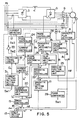
- FIG. 5 shows a third embodiment of the present invention best adapted to effect the commercial synchronous exchange.
- the third embodiment is substantially similar to the second embodiment shown in FIG. 2 except that circuit elements 29 - 33 are further added.
- a current limiter 30 Connected to the output side of the current-reference arithmetic unit 20 is a current limiter 30 which limits the current reference I0* computed by the current-reference arithmetic unit 20 to less than a maximum allowable value I m * and which also limits the current-reference variation rate which is determined by a current limiting pattern setting device 31.
- the switching signal Sw2 is derived from a switch actuating timing circuit 32 and is inverted into the switching signal Sw3 by an inverter 33.
- the switch 2 is opened or closed.
- the output CL from the current limiting pattern setting device 31 rises at a predetermined rate.
- the speed controller 16 is still operating so that the current reference I* output from the current limiter 30 increases under the current limiting condition (the maximum value I m *).
- the switching timing circuit 32 compares the current reference I* derived from the current limiter 30 with the output CL from the current limiting pattern setting device 31 and at a time t0 when a difference between I* and CL occurs, the switching signal Sw2 rises to the HIGH level.
- the inverter 33 inverts the signal Sw2 into the signal Sw3 which is at the LOW level.
- the commercial-power-supply-side switch 2 is opened.
- FIG. 7 shows a block diagram of a circuit adapted to accomplish the exchange operation described above with reference to FIG. 6.
- the comparator 34 compares the current reference I0* from the current-reference arithmetic unit 20 with the output signal CL from the current limiting pattern setting device 31 and delivers a difference ⁇ I therebetween.
- An absolute-value conversion circuit 35 outputs the absolute value
- a second comparator 36 compares the set point value Y of a setting device 38 with the absolute value
- the inverter 33 outputs the signal Sw3 in response to which the commercial-power-supply-side switch 2 is opened.
- a delay circuit 37 is provided so that the signal Sw2 is output with a time delay T d with respect to the time t0 (See FIG. 6) when the signal A is output from the comparator 36 after the comparator 36 has compared the absolute value
- the signal Sw2 is inverted into the signal Sw3 by the inverter 33. As described above, the signal Sw2 with a predetermined time delay is generated so that more positive exchange operation can be ensured.
- FIG. 8 shows a fourth embodiment of the present invention best adapted to execute not only the commercial synchronous switching but also the commercial synchronous exchange.
- a frequency converter 40 is used instead of the commutator and the inverter.
- the speed-reference-correction arithmetic unit 42 computes a speed reference correction value ⁇ a * which makes zero the phase difference ⁇ between the phase ⁇ p of the voltage of the commercial power supply PS which is detected by the instrument transformer 9 on the one hand, and the phase ⁇ v of the output voltage from the frequency converter 40 which is detected by an instrument transformer 41.
- the sum of the speed reference correction value ⁇ a * and the speed reference ⁇ * derived from the speed setting device 13 is regarded as a corrected speed reference and is compared with the speed ⁇ .
- a magnetic flux setting device 44 generates an excitation current reference I d * corresponding to a desired magnetic flux reference ⁇ *.
- a current-reference arithmetic unit 45 determines the amplitude reference I* and the phase reference ⁇ * of the primary current of the motor in response to the torque current reference I q *, the excitation current reference I d * and the speed ⁇ .
- a current controller 46 performs the phase control of the frequency converter 40 in such a way that the feedback current I detected by the current transformer 11 becomes equal to the current reference (I*, ⁇ *) derived from the current-reference arithmetic
- the speed controller 43, the current-reference arithmetic unit 45, the current controller 46, the frequency converter 40 and the speed-reference-correction arithmetic unit 42 constitute a phase-locked loop (PLL) so that the speed-reference-correction value ⁇ a * which decreases the phase difference ⁇ is generated.
- PLL phase-locked loop
- the frequency converter 40 controls the speed ⁇ of the induction motor 1 and then the speed-reference-correction arithmetic unit 42 computes a speed reference correction value ⁇ a * which makes zero the difference in phase ⁇ between the phase ⁇ p of the commercial power supply voltage and the phase ⁇ v of the converter output voltage and which is added to the speed reference ⁇ *.
- the speed reference correction value ⁇ a * serves to control the slip frequency so that the primary frequency becomes equal to the frequency of the commercial power supply.
- the commerical power supply PS is switched to the frequency converter 40 in a manner substantially similar to that described above. That is, the frequency converter 40 is driven with the converter-side switch 6 being closed; the phase ⁇ v of the converter output voltage is detected to generate the speed reference correction value ⁇ a *, is generated so that the phase difference ⁇ between the phase ⁇ v and the phase ⁇ p of the commercial power supply voltage becomes minimum; and when the phase difference ⁇ becomes sufficiently small, the converter side switch 6 is closed. Thereafter, the commercial-power-supply side switch 2 is opened, whereby the commercial synchronous exchange is completed.
- Referene numeral 47 designates a voltage-phase arithmetic unit which estimates an output voltage phase ⁇ v in response to the output signal derived from the current controller 46.
- the speed-reference arithmetic unit 19 responds to the phase difference ⁇ to compute a torque current reference I qa * which makes the phase difference ⁇ zero.
- the torque current reference I qa * or the torque current reference I q * from the speed controller 43 is applied through the switch 16 to the current reference arithmetic unit 45.
- the current-reference arithmetic unit 45 outputs the amplitude reference I* and the phase reference ⁇ * of the primary current.
- the current controller 46 delivers to the frequency converter 50 the control signal in response to which the amplitude reference I* and the phase reference ⁇ * of the primary current can be attained.
- the voltage-phase arithmetic unit 47, the speed-reference arithmetic unit 19, the current-reference arithmetic unit 45 and the current controller 46 constitute a phase-locked loop or PLL which in turn delivers the torque current reference I qa * which decreases the phase difference ⁇ to a minimum.
- the converter-side switch 16 When the phase difference ⁇ is sufficiently decreased while only the operation of the control circuit for the frequency converter 50 is continued, the converter-side switch 16 is closed so that the frequency converter 50 delivers the output voltage whose phase ⁇ v coincides with the phase ⁇ v of the commercial power supply voltage and thereafter the commercial-power-supply-side switch 2 opened. Simultaneously the switch 16 is switched to the speed controller side 43 and thereafter the frequency converter 50 controls the rotational speed of the induction motor 1. Thus, the commercial synchronous exchange is completed.
Landscapes
- Engineering & Computer Science (AREA)
- Power Engineering (AREA)
- Control Of Ac Motors In General (AREA)
Applications Claiming Priority (4)
| Application Number | Priority Date | Filing Date | Title |
|---|---|---|---|
| JP62237302A JPH07108109B2 (ja) | 1987-09-24 | 1987-09-24 | 電動機制御装置 |
| JP237302/87 | 1987-09-24 | ||
| JP63000209A JP2645049B2 (ja) | 1988-01-04 | 1988-01-04 | 誘導電動機の制御装置 |
| JP209/88 | 1988-01-04 |
Publications (3)
| Publication Number | Publication Date |
|---|---|
| EP0308974A2 true EP0308974A2 (de) | 1989-03-29 |
| EP0308974A3 EP0308974A3 (en) | 1990-09-26 |
| EP0308974B1 EP0308974B1 (de) | 1994-01-19 |
Family
ID=26333138
Family Applications (1)
| Application Number | Title | Priority Date | Filing Date |
|---|---|---|---|
| EP88115737A Expired - Lifetime EP0308974B1 (de) | 1987-09-24 | 1988-09-23 | Induktionsmotorregelsystem |
Country Status (3)
| Country | Link |
|---|---|
| EP (1) | EP0308974B1 (de) |
| KR (1) | KR920001676B1 (de) |
| DE (1) | DE3887241T2 (de) |
Cited By (2)
| Publication number | Priority date | Publication date | Assignee | Title |
|---|---|---|---|---|
| EP0279428B1 (de) * | 1987-02-17 | 1993-12-29 | Kabushiki Kaisha Toshiba | Regelsystem für einen elektrischen Motor |
| WO1994001915A1 (en) * | 1992-07-03 | 1994-01-20 | Powerline Systems Pty. Limited | Method and apparatus for an asynchronous static switch |
Families Citing this family (1)
| Publication number | Priority date | Publication date | Assignee | Title |
|---|---|---|---|---|
| RU2334338C1 (ru) * | 2007-04-26 | 2008-09-20 | ООО ВДТ-Тольятти | Устройство регулирования частоты вращения асинхронного электродвигателя |
Family Cites Families (4)
| Publication number | Priority date | Publication date | Assignee | Title |
|---|---|---|---|---|
| JPS558250A (en) * | 1978-06-30 | 1980-01-21 | Mitsubishi Electric Corp | Method restarting induction motor |
| KR930004379B1 (ko) * | 1983-11-16 | 1993-05-27 | 가부시끼가이샤 히다찌세이사꾸쇼 | 냉장고의 제어장치 |
| JPS6152179A (ja) * | 1984-08-22 | 1986-03-14 | Toshiba Corp | 電動機駆動用電源装置 |
| JPS62104493A (ja) * | 1985-10-30 | 1987-05-14 | Toshiba Corp | 交流電動機の駆動装置 |
-
1988
- 1988-09-23 DE DE3887241T patent/DE3887241T2/de not_active Expired - Fee Related
- 1988-09-23 EP EP88115737A patent/EP0308974B1/de not_active Expired - Lifetime
- 1988-09-23 KR KR1019880012355A patent/KR920001676B1/ko not_active Expired
Cited By (2)
| Publication number | Priority date | Publication date | Assignee | Title |
|---|---|---|---|---|
| EP0279428B1 (de) * | 1987-02-17 | 1993-12-29 | Kabushiki Kaisha Toshiba | Regelsystem für einen elektrischen Motor |
| WO1994001915A1 (en) * | 1992-07-03 | 1994-01-20 | Powerline Systems Pty. Limited | Method and apparatus for an asynchronous static switch |
Also Published As
| Publication number | Publication date |
|---|---|
| EP0308974B1 (de) | 1994-01-19 |
| KR920001676B1 (ko) | 1992-02-22 |
| DE3887241T2 (de) | 1994-08-04 |
| DE3887241D1 (de) | 1994-03-03 |
| KR890005965A (ko) | 1989-05-18 |
| EP0308974A3 (en) | 1990-09-26 |
Similar Documents
| Publication | Publication Date | Title |
|---|---|---|
| US5212438A (en) | Induction motor control system | |
| US5656911A (en) | Circuit for driving permanent-magnet synchronous motor using proportional controller | |
| US5160878A (en) | Induction motor controller providing temperature compensation | |
| US4227138A (en) | Reversible variable frequency oscillator for smooth reversing of AC motor drives | |
| US4282473A (en) | Rotating field machine drive and method | |
| US20030071596A1 (en) | Controller for a wound rotor slip ring induction machine | |
| EP3681029B1 (de) | Stromumwandlungsvorrichtung | |
| EP1536552B1 (de) | Sensorloses vektorsteuerverfahren für einen wechselstromgenerator und steuereinrichtung dafür | |
| EP0308974B1 (de) | Induktionsmotorregelsystem | |
| US20190356248A1 (en) | Control apparatus for a synchronous motor | |
| JP3419239B2 (ja) | モータの制御装置並びにその位置補正方法 | |
| JP2023051558A (ja) | モータ制御装置 | |
| JPH04364384A (ja) | 誘導電動機の抵抗推定起動装置 | |
| JPH0880098A (ja) | 電動機のベクトル制御装置 | |
| JP4651087B2 (ja) | 電動機制御装置 | |
| JP2645049B2 (ja) | 誘導電動機の制御装置 | |
| JP2000014041A (ja) | 電力変換装置 | |
| US7034510B2 (en) | Method for coupling inverter to alternating voltage | |
| JPH07108109B2 (ja) | 電動機制御装置 | |
| JPH089682A (ja) | 誘導機制御装置 | |
| JP2590194B2 (ja) | 交流電動機の制御装置 | |
| JP2804035B2 (ja) | 誘導機の制御装置 | |
| JP2022049489A (ja) | 電力変換システム | |
| JP2528953B2 (ja) | 誘導電動機の速度制御装置 | |
| JP4021192B2 (ja) | 可変速発電機の制御方法と装置及び可変速揚水発電システム |
Legal Events
| Date | Code | Title | Description |
|---|---|---|---|
| PUAI | Public reference made under article 153(3) epc to a published international application that has entered the european phase |
Free format text: ORIGINAL CODE: 0009012 |
|
| 17P | Request for examination filed |
Effective date: 19881019 |
|
| AK | Designated contracting states |
Kind code of ref document: A2 Designated state(s): CH DE FR GB LI |
|
| PUAL | Search report despatched |
Free format text: ORIGINAL CODE: 0009013 |
|
| AK | Designated contracting states |
Kind code of ref document: A3 Designated state(s): CH DE FR GB LI |
|
| RHK1 | Main classification (correction) |
Ipc: H02P 5/40 |
|
| 17Q | First examination report despatched |
Effective date: 19920716 |
|
| GRAA | (expected) grant |
Free format text: ORIGINAL CODE: 0009210 |
|
| AK | Designated contracting states |
Kind code of ref document: B1 Designated state(s): CH DE FR GB LI |
|
| REF | Corresponds to: |
Ref document number: 3887241 Country of ref document: DE Date of ref document: 19940303 |
|
| ET | Fr: translation filed | ||
| PGFP | Annual fee paid to national office [announced via postgrant information from national office to epo] |
Ref country code: CH Payment date: 19940923 Year of fee payment: 7 |
|
| PLBE | No opposition filed within time limit |
Free format text: ORIGINAL CODE: 0009261 |
|
| STAA | Information on the status of an ep patent application or granted ep patent |
Free format text: STATUS: NO OPPOSITION FILED WITHIN TIME LIMIT |
|
| 26N | No opposition filed | ||
| PGFP | Annual fee paid to national office [announced via postgrant information from national office to epo] |
Ref country code: GB Payment date: 19950914 Year of fee payment: 8 |
|
| PG25 | Lapsed in a contracting state [announced via postgrant information from national office to epo] |
Ref country code: LI Effective date: 19950930 Ref country code: CH Effective date: 19950930 |
|
| REG | Reference to a national code |
Ref country code: CH Ref legal event code: PL |
|
| PG25 | Lapsed in a contracting state [announced via postgrant information from national office to epo] |
Ref country code: GB Effective date: 19960923 |
|
| GBPC | Gb: european patent ceased through non-payment of renewal fee |
Effective date: 19960923 |
|
| REG | Reference to a national code |
Ref country code: FR Ref legal event code: D6 |
|
| PGFP | Annual fee paid to national office [announced via postgrant information from national office to epo] |
Ref country code: FR Payment date: 19990909 Year of fee payment: 12 |
|
| PGFP | Annual fee paid to national office [announced via postgrant information from national office to epo] |
Ref country code: DE Payment date: 19990927 Year of fee payment: 12 |
|
| PG25 | Lapsed in a contracting state [announced via postgrant information from national office to epo] |
Ref country code: FR Free format text: LAPSE BECAUSE OF NON-PAYMENT OF DUE FEES Effective date: 20010531 |
|
| PG25 | Lapsed in a contracting state [announced via postgrant information from national office to epo] |
Ref country code: DE Free format text: LAPSE BECAUSE OF NON-PAYMENT OF DUE FEES Effective date: 20010601 |
|
| REG | Reference to a national code |
Ref country code: FR Ref legal event code: ST |