EP0308400B1 - Behandlungsverfahren für belichtete flachdruckplatten - Google Patents
Behandlungsverfahren für belichtete flachdruckplatten Download PDFInfo
- Publication number
- EP0308400B1 EP0308400B1 EP87902126A EP87902126A EP0308400B1 EP 0308400 B1 EP0308400 B1 EP 0308400B1 EP 87902126 A EP87902126 A EP 87902126A EP 87902126 A EP87902126 A EP 87902126A EP 0308400 B1 EP0308400 B1 EP 0308400B1
- Authority
- EP
- European Patent Office
- Prior art keywords
- plate
- water
- irradiation
- coated surface
- plates
- Prior art date
- Legal status (The legal status is an assumption and is not a legal conclusion. Google has not performed a legal analysis and makes no representation as to the accuracy of the status listed.)
- Expired - Lifetime
Links
- XLYOFNOQVPJJNP-UHFFFAOYSA-N water Substances O XLYOFNOQVPJJNP-UHFFFAOYSA-N 0.000 claims abstract description 59
- 238000010438 heat treatment Methods 0.000 claims abstract description 20
- 238000000034 method Methods 0.000 claims abstract description 20
- 238000000576 coating method Methods 0.000 claims description 13
- 239000011248 coating agent Substances 0.000 claims description 12
- 238000001816 cooling Methods 0.000 claims description 9
- 230000005855 radiation Effects 0.000 claims description 4
- 239000007921 spray Substances 0.000 claims description 3
- WTQZSMDDRMKJRI-UHFFFAOYSA-N 4-diazoniophenolate Chemical compound [O-]C1=CC=C([N+]#N)C=C1 WTQZSMDDRMKJRI-UHFFFAOYSA-N 0.000 claims description 2
- 125000003118 aryl group Chemical group 0.000 claims description 2
- 229920003986 novolac Polymers 0.000 claims description 2
- 229920005989 resin Polymers 0.000 claims description 2
- 239000011347 resin Substances 0.000 claims description 2
- 229920003987 resole Polymers 0.000 claims description 2
- 101100165186 Caenorhabditis elegans bath-34 gene Proteins 0.000 description 9
- 239000003570 air Substances 0.000 description 4
- 239000004743 Polypropylene Substances 0.000 description 3
- -1 polypropylene Polymers 0.000 description 3
- 229920001155 polypropylene Polymers 0.000 description 3
- CBENFWSGALASAD-UHFFFAOYSA-N Ozone Chemical compound [O-][O+]=O CBENFWSGALASAD-UHFFFAOYSA-N 0.000 description 2
- 239000003513 alkali Substances 0.000 description 2
- 238000006243 chemical reaction Methods 0.000 description 2
- 239000011521 glass Substances 0.000 description 2
- 230000001678 irradiating effect Effects 0.000 description 2
- 238000011144 upstream manufacturing Methods 0.000 description 2
- WOAHJDHKFWSLKE-UHFFFAOYSA-N 1,2-benzoquinone Chemical compound O=C1C=CC=CC1=O WOAHJDHKFWSLKE-UHFFFAOYSA-N 0.000 description 1
- 239000000654 additive Substances 0.000 description 1
- 239000012080 ambient air Substances 0.000 description 1
- 230000015572 biosynthetic process Effects 0.000 description 1
- 238000009835 boiling Methods 0.000 description 1
- 125000003178 carboxy group Chemical group [H]OC(*)=O 0.000 description 1
- 230000003413 degradative effect Effects 0.000 description 1
- FHIVAFMUCKRCQO-UHFFFAOYSA-N diazinon Chemical compound CCOP(=S)(OCC)OC1=CC(C)=NC(C(C)C)=N1 FHIVAFMUCKRCQO-UHFFFAOYSA-N 0.000 description 1
- 238000001035 drying Methods 0.000 description 1
- 230000000694 effects Effects 0.000 description 1
- 238000001704 evaporation Methods 0.000 description 1
- 230000008020 evaporation Effects 0.000 description 1
- 231100000206 health hazard Toxicity 0.000 description 1
- 239000007788 liquid Substances 0.000 description 1
- 229920002120 photoresistant polymer Polymers 0.000 description 1
- 230000001360 synchronised effect Effects 0.000 description 1
Images

Classifications
-
- G—PHYSICS
- G03—PHOTOGRAPHY; CINEMATOGRAPHY; ANALOGOUS TECHNIQUES USING WAVES OTHER THAN OPTICAL WAVES; ELECTROGRAPHY; HOLOGRAPHY
- G03F—PHOTOMECHANICAL PRODUCTION OF TEXTURED OR PATTERNED SURFACES, e.g. FOR PRINTING, FOR PROCESSING OF SEMICONDUCTOR DEVICES; MATERIALS THEREFOR; ORIGINALS THEREFOR; APPARATUS SPECIALLY ADAPTED THEREFOR
- G03F7/00—Photomechanical, e.g. photolithographic, production of textured or patterned surfaces, e.g. printing surfaces; Materials therefor, e.g. comprising photoresists; Apparatus specially adapted therefor
- G03F7/20—Exposure; Apparatus therefor
- G03F7/2022—Multi-step exposure, e.g. hybrid; backside exposure; blanket exposure, e.g. for image reversal; edge exposure, e.g. for edge bead removal; corrective exposure
-
- G—PHYSICS
- G03—PHOTOGRAPHY; CINEMATOGRAPHY; ANALOGOUS TECHNIQUES USING WAVES OTHER THAN OPTICAL WAVES; ELECTROGRAPHY; HOLOGRAPHY
- G03F—PHOTOMECHANICAL PRODUCTION OF TEXTURED OR PATTERNED SURFACES, e.g. FOR PRINTING, FOR PROCESSING OF SEMICONDUCTOR DEVICES; MATERIALS THEREFOR; ORIGINALS THEREFOR; APPARATUS SPECIALLY ADAPTED THEREFOR
- G03F7/00—Photomechanical, e.g. photolithographic, production of textured or patterned surfaces, e.g. printing surfaces; Materials therefor, e.g. comprising photoresists; Apparatus specially adapted therefor
- G03F7/004—Photosensitive materials
- G03F7/022—Quinonediazides
-
- G—PHYSICS
- G03—PHOTOGRAPHY; CINEMATOGRAPHY; ANALOGOUS TECHNIQUES USING WAVES OTHER THAN OPTICAL WAVES; ELECTROGRAPHY; HOLOGRAPHY
- G03F—PHOTOMECHANICAL PRODUCTION OF TEXTURED OR PATTERNED SURFACES, e.g. FOR PRINTING, FOR PROCESSING OF SEMICONDUCTOR DEVICES; MATERIALS THEREFOR; ORIGINALS THEREFOR; APPARATUS SPECIALLY ADAPTED THEREFOR
- G03F7/00—Photomechanical, e.g. photolithographic, production of textured or patterned surfaces, e.g. printing surfaces; Materials therefor, e.g. comprising photoresists; Apparatus specially adapted therefor
- G03F7/26—Processing photosensitive materials; Apparatus therefor
- G03F7/38—Treatment before imagewise removal, e.g. prebaking
Definitions
- the invention relates to the processing of exposed lithographic printing plates.
- lithographic printing plates having certain light sensitive coatings such as that comprising an orthoquinone diazide described in our British Patent 2082339, may be reversed during processing whereby a negative of an original image may be produced on the plates by the successive steps of imagewise exposing the plates, heating them to convert the coating in the irradiated areas to a form insoluble in alkaline developer and then overall exposing the plates whereby the coating in the areas not previously irradiated are decomposed to a form soluble in such developer.
- the conversion on irradiation at least of the coating of the specific example is understood to be a degradative process resulting in the formation of carboxyl groups.
- the reversal process be carried out at high speed and preferably by passing the plates through the steps of heating and overall exposing in an integrated processing machine, but whilst the thermal conversion of the coating on the imagewise exposed areas of the plates may readily be effected at high speed, difficulty has been experienced in completing the reversal process at the same speed of throughput.
- the process refers to specific relative humidities of atmospheres during two irradiation steps, but makes no reference to a specifically water-enriched environment for the second irradiation step.
- the second irradiation step takes place under conditions of relative humidity which are comparable with those found in a normal working environment, and is therefore not a water-enriched environment, and this humidity is only a higher relative humidity than that obtaining in the environment in which the first irradiation step takes place, which is carried out under artificially dry conditions i.e. at approximately 1% relative humidity.
- the Research Disclosure document does not teach the carrying out of a second irradiation step in a water enriched environment.
- the present invention therefore seeks to provide a method and apparatus for the reversal processing of lithographic printing plates having an improved irradiation stage.
- the invention provides a method for the reversal processing of a lithographic printing plate having a light sensitive coating at one surface and comprising the steps of:
- the water-rich environment is provided by means of a chamber provided with water sprays which form a high humidity surrounding atmosphere.
- the water-rich environment is provided by application of water to the coated surface of the plate. Conveniently, this may be achieved by passing the plate through a water bath.
- a cooling step is carried out between the heating step and the irradiation step.
- the light sensitive coating provided on the lithographic printing plate is preferably an aromatic quinone diazide, and optionally with a resol or Novolak resin.
- the invention provides apparatus for use in the reversal processing of a lithographic printing plate having a light sensitive coating at one surface, a portion of which surface having been imagewise exposed to actinic radiation to render the portion soluble in developer, and the apparatus comprising:
- the enclosure is formed by a water bath, and conveying means may be provided to convey a succession of plates through the heating means and the water bath.
- First and second nip rollers may be arranged to introduce the plates into the water bath and to pull the plates out of the bath after treatment.
- a cooler device may be arranged between the heating means and the water bath.
- the irradiation may be carried out using a UV lamp.
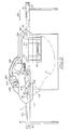
- the lithographic processing unit comprises an oven 2, a cooling unit 4 and an irradiating unit 6 through each of which plates 8-20 are passed continuously, with their sensitised surfaces uppermost and supported in conventional fashion on a plurality of endless chains 22 spaced laterally of the units so as to support the plates across their full width.
- the chains are pulled through the processing unit in the direction of arrow 32 by sprocket 54 at a speed in the range 1 m/min or faster and restrained by flanged pulleys 56 so that the upper, plate-supporting reach is taut and the lower, return, reach (not shown) is slack.
- Plate 8 is shown entering the oven 2 and plate 10 is shown within the oven which, is set at a temperature to heat the plates to between, say, 120°-140°C.
- the conventional oven may not provide enough power to raise the temperature of the plates as required during the time the plates remain therein, and it may be necessary to augment the heating step with an infra-red pre-heater 52.
- cooling unit 4 is arranged to reduce the temperature of the plates to below about 50°C.
- the cooling unit comprises a heat exchanger 24 fed with cold mains water through inlet pipe 26 and with ambient air forced through by impeller 28. Cooled are thus impinges on the plates as they pass through the cooler, exemplified by plate 12, and escapes into the irradiating unit 6.
- a shallow bath 34 about 600 mm long and of width similar to that of the oven. Water is fed into the bath from the heat-exchanger by means of a tube 36 whilst excess water runs over a weir 58, of which the upper edge, determining the water level 42, is just below the chains 22, and is removed through outlet pipe 38.
- the chains passing over a polypropylene guide 60 at the entrance to the bath, are deflected sharply downwardly into the water by means of non-rotating transverse bar 40 from which they then incline gradually upwardly to pass out of the bath over a second polypropylene guide 62. Whilst the trailing edges of the plates, which are substantially rigid, are supported by the portion of the chains leading to the guide 60, the leading edges project forwardly over the surface of the water in the bath until they come in contact with a rotary brush roller 44, located above and forwardly of the downwardly inclined portion of the chains, which presses on the leading edges of those plates, such as plate 14 shown, and guides them to enter the water and re-engage with the chains as they rise towards the guide 62.
- a housing 46 is arranged over the bath and encloses a single high-powered (5kw) UV lamp 48 arranged transversely of the direction of movement of the plates.
- the housing 46 is ventilated by air from the cooling unit which is then vented to atmosphere, by the aid of extractor fan 50. This also removes any ozone produced by lamp 48 which is a potential health hazard.
- the plates While the plates are located of the order of 30 mm below the level of the water in the bath, as plate 16 shown, they are irradiated with ultraviolet light from lamp 48 through a glass screen 64. The irradiation through the water is found to be more efficacious in the short time they are passing through the irradiation unit, than would be the case if the sensitive face of the plates were in contact with dry air.
- Fig. 2 shows a plate processing machine of a further embodiment, which may be of alternative width according to the size of plates to be processed.
- the processing machine comprises an oven 2 about 600 mm length located beneath the upper reach of a plurality of endless chains 22 upon which plates 8 to 20 are passed from an input station 3 to an output station 5.
- the chains are drawn through the machine by sprockets 49 below bath 34 and restrained by flanged pulleys 51 at both ends of the machine whereby the upper reach 7 is taut and the lower reach 9 is slack.
- the bath 34 which is of width and length similar to that of the oven is supplied with water from the heat exchanger 24, which is maintained at a constant level by conventional means not shown.
- a pair of transverse feed rollers 13 is arranged at the upstream end of the water bath 34 with the nip between them slightly below the water level, whilst a further pair of rollers 15 is arranged at the downstream end of the bath with its nip just out of the water.
- a perforated bed 17 of polypropylene is arranged within the bath extending transversely and, with a slight concave curvature lengthwise thereof between the roller pairs 13 and 15.
- the rollers 13 are rotated so that their contiguous surfaces move forwardly at the same rate as the chains 22 so that they receive the leading edge of successive plates and introduce them into the water in the bath as the chains 22 are diverted downwardly without causing the trailing edge to slide over the chains.
- the upper roller of the pair 13 is positioned slightly forwardly of the other in the direction of movement of the plates so that as the plates emerge forwardly of the roller pair, and because by nature they are somewhat flexible, the plates are pushed at a slight downward angle into the water until they make contact with the bed 17. Still gripped by the roller pair 13 each successive plate is then guided by the bed 17 and eventually directed upwardly and ultimately out of the water to be received in the nip between the rollers 15 of which the upper one is slightly rearward of the lower.
- the distance between the roller pairs 13 and 15 is such that the shortest plate intended to be processed on the machine will be gripped by roller pair 15 at its leading edge before the trailing edge leaves the nip of the roller pair 13.
- the rollers of the pair 15 are synchronised with the rollers 13 so that there is no slip between the plate and either pair of rollers in the event that a longer plate is held for a short time in both nips.
- the nip between the rollers 15 being above the level of water in the bath, the rollers exert a squeegee effect on the plates as they withdraw them from the bath.
- the upper reach 7 of the array of chains 22, having been diverted downwardly over portion 11, is guided under the water bath 34 and inclined upwardly forwardly of the bath, over portion 21 so as to be in a position to receive the plates emerging from the nip of the rollers 15 and convey them forwardly, as shown at 18, towards the output station 5.
- a UV lamp 48 is arranged transversely of the machine over the water bath 34, and a horizontal glass screen 64 is arranged between the lamp 48 and the bath 34.
- a plate such as plate 16 shown is arranged to be irradiated overall by means of the lamp 48 while it is being passed under the water in the bath 34 whereby any portions of the coating of the plate not exposed to actinic radiation prior to heating in the oven 2 are now rendered alkali soluble by the action of radiation from the lamp 48.
- the lamp 48 is enclosed within a housing 47 which is connected to an extractor fan 50 by which any ozone formed around the lamp 48 is withdrawn and vented to atmosphere.
- the extractor fan also serves to draw air from the vicinity of an infrared pre-heating element 52, located upstream of oven 2, and vent this to atmosphere.
- the water-rich environment surrounding the plates while they receive the irradiation is provided with a continuous layer of liquid water
Landscapes
- Physics & Mathematics (AREA)
- General Physics & Mathematics (AREA)
- Photosensitive Polymer And Photoresist Processing (AREA)
- Manufacture Or Reproduction Of Printing Formes (AREA)
- Printing Plates And Materials Therefor (AREA)
- Developing Agents For Electrophotography (AREA)
- Registering Or Overturning Sheets (AREA)
Claims (12)
Priority Applications (1)
| Application Number | Priority Date | Filing Date | Title |
|---|---|---|---|
| AT87902126T ATE65332T1 (de) | 1987-03-27 | 1987-03-27 | Behandlungsverfahren fuer belichtete flachdruckplatten. |
Applications Claiming Priority (1)
| Application Number | Priority Date | Filing Date | Title |
|---|---|---|---|
| PCT/GB1987/000213 WO1988007705A1 (en) | 1987-03-27 | 1987-03-27 | Processing of exposed lithographic printing plates |
Publications (2)
| Publication Number | Publication Date |
|---|---|
| EP0308400A1 EP0308400A1 (de) | 1989-03-29 |
| EP0308400B1 true EP0308400B1 (de) | 1991-07-17 |
Family
ID=10610329
Family Applications (1)
| Application Number | Title | Priority Date | Filing Date |
|---|---|---|---|
| EP87902126A Expired - Lifetime EP0308400B1 (de) | 1987-03-27 | 1987-03-27 | Behandlungsverfahren für belichtete flachdruckplatten |
Country Status (8)
| Country | Link |
|---|---|
| EP (1) | EP0308400B1 (de) |
| AT (1) | ATE65332T1 (de) |
| AU (1) | AU610064B2 (de) |
| DE (1) | DE3771501D1 (de) |
| DK (1) | DK163188A (de) |
| FI (1) | FI91812C (de) |
| NO (1) | NO173845C (de) |
| WO (1) | WO1988007705A1 (de) |
Families Citing this family (1)
| Publication number | Priority date | Publication date | Assignee | Title |
|---|---|---|---|---|
| DE3940911A1 (de) * | 1989-12-12 | 1991-06-13 | Hoechst Ag | Verfahren zur herstellung negativer kopien |
Family Cites Families (6)
| Publication number | Priority date | Publication date | Assignee | Title |
|---|---|---|---|---|
| NL280959A (de) * | 1961-07-28 | |||
| US3723120A (en) * | 1971-08-30 | 1973-03-27 | Du Pont | Process for hardening photohardenable images |
| US4148934A (en) * | 1977-12-02 | 1979-04-10 | W. R. Grace Ltd. | Secondary photocuring of photocured printing plate, apparatus and method |
| DE3137430A1 (de) * | 1981-09-19 | 1983-03-31 | Severin & Hackenberg GmbH, 5650 Solingen | Im horizontal-durchlaufverfahren arbeitende offset-druckplatten-einbrennmaschine |
| NL8203521A (nl) * | 1982-09-10 | 1984-04-02 | Philips Nv | Werkwijze voor het vervaardigen van een inrichting. |
| GB2171530B (en) * | 1985-02-27 | 1989-06-28 | Imtec Products Inc | Method of producing reversed photoresist images by vapour diffusion |
-
1987
- 1987-03-27 WO PCT/GB1987/000213 patent/WO1988007705A1/en not_active Ceased
- 1987-03-27 AU AU72044/87A patent/AU610064B2/en not_active Ceased
- 1987-03-27 AT AT87902126T patent/ATE65332T1/de not_active IP Right Cessation
- 1987-03-27 EP EP87902126A patent/EP0308400B1/de not_active Expired - Lifetime
- 1987-03-27 DE DE8787902126T patent/DE3771501D1/de not_active Expired - Lifetime
-
1988
- 1988-02-08 NO NO880525A patent/NO173845C/no unknown
- 1988-03-24 DK DK163188A patent/DK163188A/da not_active IP Right Cessation
-
1989
- 1989-09-04 FI FI894159A patent/FI91812C/fi not_active IP Right Cessation
Also Published As
| Publication number | Publication date |
|---|---|
| ATE65332T1 (de) | 1991-08-15 |
| FI91812C (fi) | 1994-08-10 |
| WO1988007705A1 (en) | 1988-10-06 |
| AU610064B2 (en) | 1991-05-16 |
| NO173845C (no) | 1994-02-09 |
| EP0308400A1 (de) | 1989-03-29 |
| DK163188A (da) | 1988-10-06 |
| AU7204487A (en) | 1988-11-02 |
| FI91812B (fi) | 1994-04-29 |
| DE3771501D1 (de) | 1991-08-22 |
| NO880525D0 (no) | 1988-02-08 |
| NO173845B (no) | 1993-11-01 |
| DK163188D0 (da) | 1988-03-24 |
| NO880525L (no) | 1988-10-06 |
| FI894159A0 (fi) | 1989-09-04 |
Similar Documents
| Publication | Publication Date | Title |
|---|---|---|
| US4927741A (en) | Processing of exposed lithographic printing plates by conducting second exposure under water | |
| US3589261A (en) | Photographic developing apparatus | |
| DE69912211T2 (de) | Heizvorrichtung | |
| EP0308400B1 (de) | Behandlungsverfahren für belichtete flachdruckplatten | |
| US11422467B2 (en) | Apparatus and method for developing printing precursors | |
| DE2632621A1 (de) | Geraet zur entwicklung und fixierung von film | |
| US3635144A (en) | Floating film photographic developing apparatus | |
| JP2568447B2 (ja) | 印刷原板を処理するための装置及び方法 | |
| GB2188448A (en) | Processing of lithographic printing plates | |
| US4841320A (en) | Developing device for photosensitive material | |
| JP2598059B2 (ja) | 露光式石版の製造方法 | |
| EP0962823A1 (de) | Verfahren und Vorrichtung zum trocknen von Lichtempfindlichen Material mittels Strahlungswärme und Luftdurchlassöffnungen | |
| US4903595A (en) | Arrangement for producing a plurality of printing forms automatically and in sequence | |
| US5568693A (en) | Method and an apparatus for the processing of photographic sheet material | |
| US3630213A (en) | Web transport apparatus | |
| US3710703A (en) | Web transport apparatus | |
| JP3781226B2 (ja) | 加熱装置 | |
| FR2411432A1 (fr) | Procede d'impressions couleur photochimique et dispositif pour sa mise en oeuvre | |
| US5800968A (en) | Method for heat developing photosensitive material and apparatus therefor | |
| US6092303A (en) | Apparatus and method for drying photosensitive material using radiant section and an air flow section | |
| EP0096766A3 (en) | Process for the treatment of flexible printing plates obtained by a photochemical process | |
| US4142795A (en) | Developer apparatus for diazo copying machines | |
| PT84641B (pt) | Metodo e aparelho para o processamento de reversao de placas litograficas de impressao | |
| JP2667066B2 (ja) | 電子写真製版装置 | |
| JP3405860B2 (ja) | エッチング製品の製造方法および製造装置 |
Legal Events
| Date | Code | Title | Description |
|---|---|---|---|
| PUAI | Public reference made under article 153(3) epc to a published international application that has entered the european phase |
Free format text: ORIGINAL CODE: 0009012 |
|
| AK | Designated contracting states |
Kind code of ref document: A1 Designated state(s): AT BE CH DE FR GB IT LI LU NL SE |
|
| 17P | Request for examination filed |
Effective date: 19890204 |
|
| 17Q | First examination report despatched |
Effective date: 19890904 |
|
| ITF | It: translation for a ep patent filed | ||
| GRAA | (expected) grant |
Free format text: ORIGINAL CODE: 0009210 |
|
| AK | Designated contracting states |
Kind code of ref document: B1 Designated state(s): AT BE CH DE FR GB IT LI LU NL SE |
|
| PG25 | Lapsed in a contracting state [announced via postgrant information from national office to epo] |
Ref country code: LI Effective date: 19910717 Ref country code: CH Effective date: 19910717 Ref country code: BE Effective date: 19910717 |
|
| REF | Corresponds to: |
Ref document number: 65332 Country of ref document: AT Date of ref document: 19910815 Kind code of ref document: T |
|
| REF | Corresponds to: |
Ref document number: 3771501 Country of ref document: DE Date of ref document: 19910822 |
|
| ET | Fr: translation filed | ||
| REG | Reference to a national code |
Ref country code: CH Ref legal event code: PL |
|
| PG25 | Lapsed in a contracting state [announced via postgrant information from national office to epo] |
Ref country code: LU Free format text: LAPSE BECAUSE OF NON-PAYMENT OF DUE FEES Effective date: 19920331 |
|
| PLBE | No opposition filed within time limit |
Free format text: ORIGINAL CODE: 0009261 |
|
| STAA | Information on the status of an ep patent application or granted ep patent |
Free format text: STATUS: NO OPPOSITION FILED WITHIN TIME LIMIT |
|
| 26N | No opposition filed | ||
| EAL | Se: european patent in force in sweden |
Ref document number: 87902126.9 |
|
| PGFP | Annual fee paid to national office [announced via postgrant information from national office to epo] |
Ref country code: SE Payment date: 19980217 Year of fee payment: 12 |
|
| PGFP | Annual fee paid to national office [announced via postgrant information from national office to epo] |
Ref country code: FR Payment date: 19990208 Year of fee payment: 13 |
|
| PGFP | Annual fee paid to national office [announced via postgrant information from national office to epo] |
Ref country code: AT Payment date: 19990210 Year of fee payment: 13 |
|
| PGFP | Annual fee paid to national office [announced via postgrant information from national office to epo] |
Ref country code: NL Payment date: 19990224 Year of fee payment: 13 |
|
| PGFP | Annual fee paid to national office [announced via postgrant information from national office to epo] |
Ref country code: DE Payment date: 19990226 Year of fee payment: 13 |
|
| PG25 | Lapsed in a contracting state [announced via postgrant information from national office to epo] |
Ref country code: SE Free format text: LAPSE BECAUSE OF NON-PAYMENT OF DUE FEES Effective date: 19990328 |
|
| REG | Reference to a national code |
Ref country code: GB Ref legal event code: 732E |
|
| EUG | Se: european patent has lapsed |
Ref document number: 87902126.9 |
|
| EUG | Se: european patent has lapsed |
Ref document number: 87902126.9 |
|
| PG25 | Lapsed in a contracting state [announced via postgrant information from national office to epo] |
Ref country code: AT Free format text: LAPSE BECAUSE OF NON-PAYMENT OF DUE FEES Effective date: 20000327 |
|
| PG25 | Lapsed in a contracting state [announced via postgrant information from national office to epo] |
Ref country code: NL Free format text: LAPSE BECAUSE OF NON-PAYMENT OF DUE FEES Effective date: 20001001 |
|
| PG25 | Lapsed in a contracting state [announced via postgrant information from national office to epo] |
Ref country code: FR Free format text: LAPSE BECAUSE OF NON-PAYMENT OF DUE FEES Effective date: 20001130 |
|
| NLV4 | Nl: lapsed or anulled due to non-payment of the annual fee |
Effective date: 20001001 |
|
| REG | Reference to a national code |
Ref country code: FR Ref legal event code: ST |
|
| PG25 | Lapsed in a contracting state [announced via postgrant information from national office to epo] |
Ref country code: DE Free format text: LAPSE BECAUSE OF NON-PAYMENT OF DUE FEES Effective date: 20010103 |
|
| PGFP | Annual fee paid to national office [announced via postgrant information from national office to epo] |
Ref country code: GB Payment date: 20010321 Year of fee payment: 15 |
|
| REG | Reference to a national code |
Ref country code: GB Ref legal event code: IF02 |
|
| PG25 | Lapsed in a contracting state [announced via postgrant information from national office to epo] |
Ref country code: GB Free format text: LAPSE BECAUSE OF NON-PAYMENT OF DUE FEES Effective date: 20020327 |
|
| GBPC | Gb: european patent ceased through non-payment of renewal fee |
Effective date: 20020327 |
|
| PG25 | Lapsed in a contracting state [announced via postgrant information from national office to epo] |
Ref country code: IT Free format text: LAPSE BECAUSE OF NON-PAYMENT OF DUE FEES;WARNING: LAPSES OF ITALIAN PATENTS WITH EFFECTIVE DATE BEFORE 2007 MAY HAVE OCCURRED AT ANY TIME BEFORE 2007. THE CORRECT EFFECTIVE DATE MAY BE DIFFERENT FROM THE ONE RECORDED. Effective date: 20050327 |