EP0306830B1 - Machine pour mesurer les coordonnées - Google Patents
Machine pour mesurer les coordonnées Download PDFInfo
- Publication number
- EP0306830B1 EP0306830B1 EP88114263A EP88114263A EP0306830B1 EP 0306830 B1 EP0306830 B1 EP 0306830B1 EP 88114263 A EP88114263 A EP 88114263A EP 88114263 A EP88114263 A EP 88114263A EP 0306830 B1 EP0306830 B1 EP 0306830B1
- Authority
- EP
- European Patent Office
- Prior art keywords
- belt
- threaded spindle
- measuring machine
- disc
- coordinate measuring
- Prior art date
- Legal status (The legal status is an assumption and is not a legal conclusion. Google has not performed a legal analysis and makes no representation as to the accuracy of the status listed.)
- Expired - Lifetime
Links
- 238000012806 monitoring device Methods 0.000 claims description 5
- 238000012544 monitoring process Methods 0.000 claims description 4
- 238000010276 construction Methods 0.000 description 2
- 239000000463 material Substances 0.000 description 2
- 230000005540 biological transmission Effects 0.000 description 1
- 230000008878 coupling Effects 0.000 description 1
- 238000010168 coupling process Methods 0.000 description 1
- 238000005859 coupling reaction Methods 0.000 description 1
- 238000009434 installation Methods 0.000 description 1
- 239000002184 metal Substances 0.000 description 1
Images
Classifications
-
- G—PHYSICS
- G01—MEASURING; TESTING
- G01B—MEASURING LENGTH, THICKNESS OR SIMILAR LINEAR DIMENSIONS; MEASURING ANGLES; MEASURING AREAS; MEASURING IRREGULARITIES OF SURFACES OR CONTOURS
- G01B5/00—Measuring arrangements characterised by the use of mechanical techniques
- G01B5/0002—Arrangements for supporting, fixing or guiding the measuring instrument or the object to be measured
-
- G—PHYSICS
- G01—MEASURING; TESTING
- G01B—MEASURING LENGTH, THICKNESS OR SIMILAR LINEAR DIMENSIONS; MEASURING ANGLES; MEASURING AREAS; MEASURING IRREGULARITIES OF SURFACES OR CONTOURS
- G01B5/00—Measuring arrangements characterised by the use of mechanical techniques
- G01B5/004—Measuring arrangements characterised by the use of mechanical techniques for measuring coordinates of points
- G01B5/008—Measuring arrangements characterised by the use of mechanical techniques for measuring coordinates of points using coordinate measuring machines
Definitions
- the invention relates to a coordinate measuring machine with a drive and braking device of the quill which can be moved in the Z direction by means of a threaded spindle.
- DE-A-3121363 discloses a drive device on a coordinate measuring machine which serves to move a quill in the Z direction by means of a threaded spindle.
- the document DE-A-3514961 is about the fact that with such a drive device a radial runout of the threaded spindle is not transmitted to the sleeve and in addition a wobble axis movement is possible.
- this object is achieved in that the axially parallel motor output shaft and threaded spindle are in drive connection with one another by means of a belt drive with belt tensioning and monitoring device, a brake disk being flanged to the belt wheel for driving the threaded spindle, onto which brake shoes a brake caliper or a Apply the disc brake.
- the pulley mounted on the motor output shaft can be displaced transversely to the longitudinal axis of the motor output shaft by means of a motor plate which can be displaced and fastened in elongated holes.
- the second pulley can be mounted on the threaded spindle of the quill in a rotationally fixed manner together with the brake disc flanged to it in a rotationally fixed manner.
- the second pulley with the brake disc can be secured on the threaded spindle by an adapter sleeve.
- a further safeguard is given by the fact that the second pulley and the brake disk are additionally secured on the threaded spindle by means of a driving disk which engages in a longitudinal groove machined into the threaded spindle.
- a safety limit switch in connection with a double ball bearing can be attached to the belt for monitoring the belt tension and the belt movement.
- the belt tensioner can be an angle lever, which rests under spring force on the belt with a roller or an impeller and pivots through a motor unit about a central axis.
- the technical improvement of the drive and braking device lies in the relatively simple construction and in the safe function, because in particular the braking device acts directly on the threaded spindle. It is a further advantage that only a single belt is sufficient for the selected drive device, since the new disc brake acts directly on the threaded spindle.
- the motor plate can be displaced in the direction of the large pulley of the threaded spindle via elongated holes.
- the new belt monitoring with the safety limit switch and a double ball bearing are attached to the belt for a better fit.
- the brake disc is flanged and secured directly to the second pulley of the threaded spindle.
- the belt wheel with the brake disc is connected to the threaded spindle with an adapter sleeve.
- a special drive plate is provided according to the further features of the invention, which engages with play in a groove machined in the shaft. This inevitably ensures a rotary drive even if the adapter sleeve connection fails.
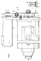
- a sleeve 3 On a coordinate measuring machine (not shown in detail) there is a sleeve 3 which can be moved in the Z direction 2 in a housing 1. The movement of this sleeve 3 in the Z direction takes place via a threaded spindle 4 on which a driving nut 5 is axially displaceable but non-rotatable is arranged.
- the driving nut 5 is firmly connected to a nut housing 6, which in turn is connected to the sleeve, for example by screws 7.
- the threaded spindle 4 is driven by an electric motor 8 which is arranged axially parallel. With its front face 9, the electric motor 8 is connected to a motor plate 10 by screws 11. In side tabs 12 of the motor plate 10 there are elongated holes 13 into which screws 14 are inserted in order to be able to mount the motor plate 10 together with the electric motor 8 on a stationary component. The position of the elongated holes 13 is such that the motor plate 10 can be moved together with the electric motor 8 perpendicular to the axis-parallel threaded spindle 4. This finally makes it possible to bring about a belt tension between the threaded spindle 4 and the motor output shaft 16, which protrudes from the front of the motor 8 and the motor plate 10.
- a pulley 17 is rotatably and axially immovable.
- An endless belt 18 represents the drive connection between the pulley 17, the motor output shaft 16 and the second pulley 19 of the threaded spindle 4.
- a brake disk 20 is flanged on the end face of this second pulley 19, which can be done, for example, by a screw connection.
- the second pulley 19, together with the brake disc 20, is secured against rotation on the threaded spindle by a clamping sleeve 21.
- An additional securing for a rotary driving of the pulley 19 with brake disk 20 on the threaded spindle 4 is done by a locking ring 22 which engages with a lug 23 in a longitudinal groove 24 of the threaded spindle 4.
- Brake shoes 25 'of a brake caliper 26' are operatively connected to the brake disk 20, which is fixedly mounted radially outside the brake disk 20 on the stationary component 15.
- the brake disc 20 is relatively narrow, for example only 5 mm.
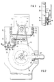
- a belt tensioning device 25 with a monitoring device 26 for the belt tension is provided on the side of the belt 18.
- the belt tensioning device consists of an angle lever 27, the two legs 28 and 29 of which can be pivoted about the central axis 30.
- a double ball bearing 31 is rotatably arranged for engagement with the belt 18. This double ball bearing 31 is held in constant contact with the belt 18 by means of a tension spring 32.
- the tension of the belt is monitored by a safety limit switch 33, which is connected to the second lever arm 28 of the angle lever 27 by a screw 34.
- the switch 33 in turn is connected to the fixed component 15 by screws 35.
- this drive and braking device for the threaded spindle of a quill of a coordinate measuring machine can be seen in the fact that the first pulley 17 is mounted directly on the motor output shaft 16 and that only a single belt serves as a transmission element, which is possible in that this Disc brake 20, 25 acts directly on the threaded spindle 4 for the movement of the sleeve 3.
- the belt 18 can be tensioned in a simple manner by displacing the motor plate 10 within the elongated holes 13. An improved installation of the belt tensioning and the belt tension monitoring device is achieved by the double ball bearings 31 and the safety limit switch 33.
- the brake disc 20 is screwed directly onto the second pulley 19 and secured there.
- the pulley is mounted together with the brake disc 20 with an adapter sleeve 21 on the threaded spindle 4 for a rotary drive.
- An additional security of this adapter sleeve connection is carried out with an additional locking washer 22, so as to ensure that the pulley 19 is driven on the threaded spindle 4 even in the event of material or assembly errors.
Landscapes
- Physics & Mathematics (AREA)
- General Physics & Mathematics (AREA)
- A Measuring Device Byusing Mechanical Method (AREA)
- Length Measuring Devices With Unspecified Measuring Means (AREA)
- Devices For Conveying Motion By Means Of Endless Flexible Members (AREA)
Claims (7)
- Machine de mesure de coordonnées, comprenant un système d'entraînement et de freinage du fourreau de contre-pointe (3) déplaçable dans le sens Z au moyen d'une broche filetée (4), caractérisée en ce que l'arbre de sortie de moteur (16) et la broche filetée (4), dont les axes sont parallèles l'un à l'autre, sont entraînés ensemble par un entraînement à courroie (16, 18, 19) comportant un système de tension et de surveillance de courroie (25, 26), un disque de freinage (20) sur lequel agissent des mâchoires de freinage (25') d'une griffe de freinage (26') ou d'un frein à disque étant bridé sur le volant (19) d'entraînement de la broche filetée (4).
- Machine de mesure de coordonnées selon la revendication 1, caractérisée en ce que la poulie (17) montée sur l'arbre de sortie de moteur (16) peut être réglée transversalement à l'axe longitudinal de l'arbre de sortie de moteur (16) au moyen d'un socle de moteur (10) pouvant être déplacé et immobilisé dans des trous oblongs (13).
- Machine de mesure de coordonnées selon la revendication 1, caractérisée en ce que la seconde poulie (19), avec le disque de freinage (20) qui y est bridé de manière solidaire en rotation, est liée en rotation avec la broche filetée (4) du fourreau de contre-pointe (3).
- Machine de mesure de coordonnées selon les revendications 1 et 3, caractérisée en ce que la seconde poulie (19) associée au disque de freinage (20) est bloquée sur la broche filetée (4) par un manchon de serrage (21).
- Machine de mesure de coordonnées selon les revendications 1, 3 et 4, caractérisée en ce que la seconde poulie (19) et le disque de freinage (20) sont également bloqués sur la broche filetée (4) par un plateau d'entraînement (22) qui s'engage dans une rainure longitudinale (24) pratiquée dans la broche filetée (4).
- Machine de mesure de coordonnées selon la revendication 1, caractérisée en ce que, pour surveiller la tension et le déplacement de la courroie, il est prévu un commutateur de position extrême de course (33) associé à un double roulement à billes (31) appliqué contre la courroie (18).
- Machine de mesure de coordonnées selon les revendications 1 et 6, caractérisée en ce que le tendeur de courroie est un levier coudé (27) qui est appliqué, sous une force élastique, contre la courroie (18) avec un galet ou une roue mobile, ou directement avec un double roulement à billes (31), et qui peut pivoter par l'intermédiaire d'un axe central (30).
Applications Claiming Priority (2)
| Application Number | Priority Date | Filing Date | Title |
|---|---|---|---|
| DE3729813 | 1987-09-05 | ||
| DE19873729813 DE3729813A1 (de) | 1987-09-05 | 1987-09-05 | Koordinaten-messmaschine |
Publications (3)
| Publication Number | Publication Date |
|---|---|
| EP0306830A2 EP0306830A2 (fr) | 1989-03-15 |
| EP0306830A3 EP0306830A3 (fr) | 1991-04-17 |
| EP0306830B1 true EP0306830B1 (fr) | 1992-12-02 |
Family
ID=6335343
Family Applications (1)
| Application Number | Title | Priority Date | Filing Date |
|---|---|---|---|
| EP88114263A Expired - Lifetime EP0306830B1 (fr) | 1987-09-05 | 1988-09-01 | Machine pour mesurer les coordonnées |
Country Status (3)
| Country | Link |
|---|---|
| US (1) | US4889519A (fr) |
| EP (1) | EP0306830B1 (fr) |
| DE (2) | DE3729813A1 (fr) |
Families Citing this family (12)
| Publication number | Priority date | Publication date | Assignee | Title |
|---|---|---|---|---|
| DE4118389C1 (en) * | 1991-06-05 | 1992-12-24 | Roland 2000 Hamburg De Stawinoga | V=belt drive for lift - has motor with pivot directly below it and spring to tension belt |
| US5240461A (en) * | 1992-07-01 | 1993-08-31 | Deere & Company | Blower mounting with belt tensioner |
| US5362279A (en) * | 1993-08-05 | 1994-11-08 | Cms Gilbreth Packaging Systems | Self-tensioning chain drive |
| DE19638877C2 (de) * | 1996-09-23 | 1999-11-18 | Wolfgang Heyng | Zahnriemen-Antriebsrad für ein Fahrzeugrad |
| KR100625072B1 (ko) * | 2002-01-29 | 2006-09-19 | 가부시키가이샤 제이텍트 | 전동 파워스티어링 장치 |
| DE10333561B4 (de) * | 2003-07-23 | 2006-07-06 | Carl Zeiss Industrielle Messtechnik Gmbh | Koordinaten-Meßmaschine |
| US7587834B2 (en) * | 2008-02-07 | 2009-09-15 | Eaton Homer L | Motorized coordinate measuring device |
| US20110294614A1 (en) * | 2010-06-01 | 2011-12-01 | Bigler Jeremy M | Belt tensioning system |
| EP3128291B1 (fr) * | 2015-08-03 | 2023-10-04 | Hexagon Technology Center GmbH | Machine de mesure de coordonnées avec tête de sonde guidée par l'entraînement d'une courroie |
| DE102015217216A1 (de) * | 2015-09-09 | 2017-03-09 | Frankl & Kirchner GmbH & Co KG Fabrik für Elektromotoren u. elektrische Apparate | Anbau-Antriebsmotor-Baugruppe für eine Nähmaschine |
| US10066709B2 (en) * | 2015-10-19 | 2018-09-04 | Fna Group, Inc. | Mounting alignment system |
| US11359710B1 (en) * | 2018-06-01 | 2022-06-14 | Hudson Products Corporation | Drive belt tensioning system for air-cooled heat exchangers |
Family Cites Families (8)
| Publication number | Priority date | Publication date | Assignee | Title |
|---|---|---|---|---|
| US3004443A (en) * | 1960-01-11 | 1961-10-17 | Alfred W Gerrans | Adjustable take-up mechanism |
| US3262330A (en) * | 1964-06-18 | 1966-07-26 | Deere & Co | Baler pick-up drive and counterbalance |
| US3977266A (en) * | 1975-07-28 | 1976-08-31 | Rohr Industries, Inc. | Multiple belt tension control mechanism |
| US4205509A (en) * | 1977-10-05 | 1980-06-03 | Honda Giken Kogyo Kabushiki Kaisha | Power transmission device for power-operated lawn mowing machine |
| CH654781A5 (de) * | 1981-02-20 | 1986-03-14 | Hauni Werke Koerber & Co Kg | Werkzeugmaschine, insbesondere flachschleifmaschine. |
| DE3121363C2 (de) * | 1981-05-29 | 1983-11-10 | Mauser-Werke Oberndorf Gmbh, 7238 Oberndorf | Antriebseinrichtung an einer Koordinatenmeßmaschine |
| US4561624A (en) * | 1983-06-30 | 1985-12-31 | Champion Spark Plug Company | Mounting platform |
| DE3514961A1 (de) * | 1985-04-25 | 1986-10-30 | Mauser-Werke Oberndorf Gmbh, 7238 Oberndorf | Antriebseinrichtung an einer koordinaten-messmaschine |
-
1987
- 1987-09-05 DE DE19873729813 patent/DE3729813A1/de not_active Withdrawn
-
1988
- 1988-08-09 US US07/230,469 patent/US4889519A/en not_active Expired - Fee Related
- 1988-09-01 EP EP88114263A patent/EP0306830B1/fr not_active Expired - Lifetime
- 1988-09-01 DE DE8888114263T patent/DE3876342D1/de not_active Expired - Fee Related
Also Published As
| Publication number | Publication date |
|---|---|
| DE3729813A1 (de) | 1989-03-16 |
| DE3876342D1 (de) | 1993-01-14 |
| US4889519A (en) | 1989-12-26 |
| EP0306830A2 (fr) | 1989-03-15 |
| EP0306830A3 (fr) | 1991-04-17 |
Similar Documents
| Publication | Publication Date | Title |
|---|---|---|
| EP0306830B1 (fr) | Machine pour mesurer les coordonnées | |
| EP0330672B1 (fr) | Dispositif de serrage pour le blocage axial d'un outil, notamment d'une meule | |
| EP0226828B1 (fr) | Fixation d'un générateur tachymétrique à un arbre de commande | |
| EP0130344A1 (fr) | Moteur d'accouplement | |
| EP0641621A1 (fr) | Dispositif d'entraînement rotatif | |
| DE2007849C3 (de) | Vorrichtung zum kraftschlüssigen Befestigen eines Zahnrades auf einer keillosen Welle | |
| DE3643255C2 (de) | Drehsignalgeber | |
| EP1960753B1 (fr) | Dispositif de maintien pour jante de roue de vehicule | |
| DE19715026A1 (de) | Elastischer Antrieb für Druckmaschinen | |
| DE68925213T2 (de) | Kleinbauender, automatischer Riemenspanner | |
| DE1962449A1 (de) | Spannvorrichtung fuer Wickelkerne | |
| DE3011078C2 (de) | Magnetlager | |
| DE69008088T2 (de) | Vorrichtung zur Befestigung eines Fahrzeugrades an eine Achse. | |
| EP0612651B1 (fr) | Servomoteur avec une transmission axiale notamment pour diriger un véhicule à quatre roues directrices | |
| DE60213586T2 (de) | Lenkbare radaufhängung | |
| DE3720609A1 (de) | Rolle fuer eine rollenbahn | |
| DE19517892A1 (de) | Schleifmaschine für Brillengläser mit Einrichtungen zum Regeln des Betrages der Spannung des zu schleifenden Glasrohlings | |
| EP3788268B1 (fr) | Accouplement pour un moteur électrique et moteur électrique avec un accouplement entre l'arbre du rotor et l'arbre d'un capteur d'angle | |
| DE2835258A1 (de) | Tragbare drehvorrichtung | |
| DE921658C (de) | Riemenscheibe mit eingebautem Zahnradgetriebe | |
| DE10236560B4 (de) | Mehrfach-Umdrehungszähler und Verfahren zu dessen Montage | |
| DE418401C (de) | Vierradbremse, insbesondere fuer Kraftfahrzeuge | |
| DE4034271A1 (de) | Felgenbremse fuer ein fahrrad | |
| DE69023197T2 (de) | Einrichtung zum Verbinden eines Rades mit der Achse eines Industriefahrzeuges, das mit einer Einrichtung zur Messung der Radgeschwindigkeit ausgerüstet ist. | |
| WO1999028228A1 (fr) | Tendeur de fil |
Legal Events
| Date | Code | Title | Description |
|---|---|---|---|
| PUAI | Public reference made under article 153(3) epc to a published international application that has entered the european phase |
Free format text: ORIGINAL CODE: 0009012 |
|
| AK | Designated contracting states |
Kind code of ref document: A2 Designated state(s): DE FR GB IT |
|
| PUAL | Search report despatched |
Free format text: ORIGINAL CODE: 0009013 |
|
| AK | Designated contracting states |
Kind code of ref document: A3 Designated state(s): DE FR GB IT |
|
| 17P | Request for examination filed |
Effective date: 19910410 |
|
| RHK1 | Main classification (correction) |
Ipc: G01B 21/04 |
|
| 17Q | First examination report despatched |
Effective date: 19920123 |
|
| GRAA | (expected) grant |
Free format text: ORIGINAL CODE: 0009210 |
|
| AK | Designated contracting states |
Kind code of ref document: B1 Designated state(s): DE FR GB IT |
|
| PG25 | Lapsed in a contracting state [announced via postgrant information from national office to epo] |
Ref country code: FR Free format text: THE PATENT HAS BEEN ANNULLED BY A DECISION OF A NATIONAL AUTHORITY Effective date: 19921202 |
|
| REF | Corresponds to: |
Ref document number: 3876342 Country of ref document: DE Date of ref document: 19930114 |
|
| ITF | It: translation for a ep patent filed | ||
| ET | Fr: translation filed | ||
| GBT | Gb: translation of ep patent filed (gb section 77(6)(a)/1977) |
Effective date: 19930305 |
|
| PG25 | Lapsed in a contracting state [announced via postgrant information from national office to epo] |
Ref country code: GB Effective date: 19930901 |
|
| PLBE | No opposition filed within time limit |
Free format text: ORIGINAL CODE: 0009261 |
|
| STAA | Information on the status of an ep patent application or granted ep patent |
Free format text: STATUS: NO OPPOSITION FILED WITHIN TIME LIMIT |
|
| 26N | No opposition filed | ||
| GBPC | Gb: european patent ceased through non-payment of renewal fee |
Effective date: 19930901 |
|
| PG25 | Lapsed in a contracting state [announced via postgrant information from national office to epo] |
Ref country code: DE Effective date: 19940601 |
|
| REG | Reference to a national code |
Ref country code: FR Ref legal event code: ST |
|
| PG25 | Lapsed in a contracting state [announced via postgrant information from national office to epo] |
Ref country code: IT Free format text: LAPSE BECAUSE OF NON-PAYMENT OF DUE FEES Effective date: 20050901 |