EP0306743A2 - Soot filter process and soot filter device for a diesel engine - Google Patents
Soot filter process and soot filter device for a diesel engine Download PDFInfo
- Publication number
- EP0306743A2 EP0306743A2 EP88113462A EP88113462A EP0306743A2 EP 0306743 A2 EP0306743 A2 EP 0306743A2 EP 88113462 A EP88113462 A EP 88113462A EP 88113462 A EP88113462 A EP 88113462A EP 0306743 A2 EP0306743 A2 EP 0306743A2
- Authority
- EP
- European Patent Office
- Prior art keywords
- soot filter
- filter device
- combustion chamber
- burner
- fuel
- Prior art date
- Legal status (The legal status is an assumption and is not a legal conclusion. Google has not performed a legal analysis and makes no representation as to the accuracy of the status listed.)
- Granted
Links
Images

Classifications
-
- F—MECHANICAL ENGINEERING; LIGHTING; HEATING; WEAPONS; BLASTING
- F01—MACHINES OR ENGINES IN GENERAL; ENGINE PLANTS IN GENERAL; STEAM ENGINES
- F01N—GAS-FLOW SILENCERS OR EXHAUST APPARATUS FOR MACHINES OR ENGINES IN GENERAL; GAS-FLOW SILENCERS OR EXHAUST APPARATUS FOR INTERNAL-COMBUSTION ENGINES
- F01N3/00—Exhaust or silencing apparatus having means for purifying, rendering innocuous, or otherwise treating exhaust
- F01N3/02—Exhaust or silencing apparatus having means for purifying, rendering innocuous, or otherwise treating exhaust for cooling, or for removing solid constituents of, exhaust
- F01N3/021—Exhaust or silencing apparatus having means for purifying, rendering innocuous, or otherwise treating exhaust for cooling, or for removing solid constituents of, exhaust by means of filters
- F01N3/023—Exhaust or silencing apparatus having means for purifying, rendering innocuous, or otherwise treating exhaust for cooling, or for removing solid constituents of, exhaust by means of filters using means for regenerating the filters, e.g. by burning trapped particles
- F01N3/025—Exhaust or silencing apparatus having means for purifying, rendering innocuous, or otherwise treating exhaust for cooling, or for removing solid constituents of, exhaust by means of filters using means for regenerating the filters, e.g. by burning trapped particles using fuel burner or by adding fuel to exhaust
-
- F—MECHANICAL ENGINEERING; LIGHTING; HEATING; WEAPONS; BLASTING
- F01—MACHINES OR ENGINES IN GENERAL; ENGINE PLANTS IN GENERAL; STEAM ENGINES
- F01N—GAS-FLOW SILENCERS OR EXHAUST APPARATUS FOR MACHINES OR ENGINES IN GENERAL; GAS-FLOW SILENCERS OR EXHAUST APPARATUS FOR INTERNAL-COMBUSTION ENGINES
- F01N2240/00—Combination or association of two or more different exhaust treating devices, or of at least one such device with an auxiliary device, not covered by indexing codes F01N2230/00 or F01N2250/00, one of the devices being
- F01N2240/14—Combination or association of two or more different exhaust treating devices, or of at least one such device with an auxiliary device, not covered by indexing codes F01N2230/00 or F01N2250/00, one of the devices being a fuel burner
-
- F—MECHANICAL ENGINEERING; LIGHTING; HEATING; WEAPONS; BLASTING
- F02—COMBUSTION ENGINES; HOT-GAS OR COMBUSTION-PRODUCT ENGINE PLANTS
- F02B—INTERNAL-COMBUSTION PISTON ENGINES; COMBUSTION ENGINES IN GENERAL
- F02B3/00—Engines characterised by air compression and subsequent fuel addition
- F02B3/06—Engines characterised by air compression and subsequent fuel addition with compression ignition
Definitions
- the invention relates to a soot filter device for a diesel engine according to the preamble of patent claim 1.
- diesel engines produce soot, which should be filtered out of the exhaust gases.
- Ceramic soot filters are being tested, which can absorb the soot from 5 to 8 hours of driving.
- the filter must then be regenerated.
- the regeneration is carried out by burning the soot particles with high exhaust gas temperatures of at least 600 ° C.
- Such high exhaust gas temperatures are not available in diesel engines due to the high excess air.
- Methods are currently being tested in which the filter device has its own burner. Because this burner does not counter the pulsating exhaust gas pressure of the diesel engine facilities are being tested, in which the filter is bridged by an additional silencer during regeneration.
- the invention has for its object to provide a soot filter device of the type specified in the preamble of claim 1, in which the regeneration of the filter can be carried out during operation of the diesel engine without redirecting the engine exhaust.
- soot filter device only a partial combustion of the fuel supplied takes place in the main combustion chamber of the burner with the aid of air that is forcibly fed in a certain volume flow, but without soot formation.
- the unburned part of the fuel is fed together with the fuel gases to the afterburning chamber, where it burns due to the oxygen contained in the engine exhaust.
- the first part of the combustion is carried out with external air supplied, and the engine exhaust gases are used only for post-combustion. Since compressed air is only supplied in substoichiometric amounts for the main combustion, the air requirement is relatively low.
- the atomizer nozzle of the burner is preferably an annular nozzle provided with swirl elements.
- This ring nozzle has an annular atomizing tongue, along which fuel passes along the inside, which is generated by the rotating air flow to form a flow cone is atomized. Reliable, stable combustion is achieved despite the pulsating back pressure and despite the lack of air by using such an "air atomizing nozzle". If all the air for the main combustion is supplied with a differential pressure of at least 10 mbar, an intensive mixture of fine fuel mist with the combustion air is obtained directly behind the nozzle. Together with the hot gas recirculation caused by the swirl elements of the atomizer nozzle, this leads to a combustion that is independent of the pressure pulsations.
- the compressed air supplied to the burner can be taken from the compressed air system of the vehicle and fed to the atomizer nozzle via a nozzle operated with a supercritical pressure ratio.
- Supercritical pressure ratio means that the air flows in the narrowest nozzle cross-section at least at the speed of sound. A burner output that is independent of the pressure pulsations of the engine exhaust gas can thus be operated.
- the combustion air can be conveyed by a displacement fan.
- the air mass flow is not or only slightly influenced by the back pressure of the diesel exhaust gas flow, and burner operation is ensured with an air flow rate unaffected by the pulsating engine pressure and thus unaffected burner output. If you couple the air compressor with the speed of the diesel engine and also deliver the fuel with a positive displacement pump, you get a speed-proportional mixture quantity control. If the speed of the diesel engine changes, the burner output adapts accordingly changed exhaust gas mass flow. This allows the temperature at the filter to be optimally maintained during regeneration.
- the burner is so small that it can easily be installed in the filter housing and cooled with the engine exhaust gas by means of a heat exchanger.
- the filter device shown in FIG. 1 has a cylindrical housing 10.
- the housing 10 has a radial or tangential inlet 11 for the engine exhaust gases at one end and contains a ceramic filter 12 which takes up the entire housing cross section.
- a ceramic filter 12 which takes up the entire housing cross section.
- the outlet connection 13 At the other end of the housing 10 there is the outlet connection 13, through which the engine exhaust gases and combustion gases emerge from the housing.
- the exhaust gas inlet 11 leads into an annular distributor chamber 14 which surrounds the main combustion chamber 15 of the burner 16.
- the atomizing nozzle 17 is attached to the cover wall 18 of the nozzle housing 19. This cover wall 18 is flanged to the end wall of the housing 10 and delimits the main combustion chamber 15.
- the fuel line 20 leads into the nozzle housing 19 and is connected directly to the atomizer nozzle 17.
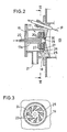
- the nozzle housing 19 also has an air inlet 21 through which compressed air is pressed into the interior of the nozzle housing. As shown in FIG. 2, the fuel line 20 leads through the interior of the nozzle body 17a and emerges from its end face.
- numerous air-conducting swirl elements 23 in the form of wings are arranged on the flange-like end wall 22 of the nozzle body.
- swirl elements 23 are inclined in the circumferential direction according to FIG. 3 and they taper towards the inner end.
- the swirl elements 23 delimit channels 24 through which the radially inflowing air contains a peripheral component.
- Each of the channels 24 decreases in cross section towards its inner end, so that the air in each channel 24 is increasingly accelerated.
- the swirl elements 23 are arranged between the end wall 22 and a plate 25 running parallel to this end wall.
- the end wall of the plate 25 facing away from the swirl elements 23 forms the boundary wall of a further nozzle space, which is also equipped with swirl elements 26 which are attached to the end face of a further plate 27.
- the plate 27 runs parallel to the plate 25 and its swirl elements 26 are designed and arranged in the same way as the swirl elements 23 of the plate 22.
- the air flowing laterally into the nozzle housing 19 through the compressed air inlet 21 is distributed in the interior of the nozzle housing and flows radially into the channels 24 between the swirl elements 23 and into the corresponding channels between the swirl elements 26.
- the swirl elements give the air a swirl, i.e. a circular motion.
- the plate 25 has an annular shape and its inner edge has the shape of an annular cutting edge 29 which projects axially in the flow direction and tapers towards the end.
- the inner edge of the annular plate 27 is also bent axially in the flow direction and forms a conical ring 30 , which surrounds the cutting edge 29 at a radial distance.
- the liquid fuel emerging from the tube 20a is caught by the rotating air stream and sprayed onto the inside of the cutting edge 29.
- the cutting edge 29 is surrounded on both sides by rotating and axially moving air streams which tear off the fuel from the circular sharp tip of the cutting edge 29 and distribute it finely and evenly in droplet form.
- the fuel droplets mix with the combustion air and together with it enter the tubular main combustion chamber 15.
- ring-shaped flow rollers in which a part of the mixture flow is returned, arise in the main combustion chamber 15 and rotate around the longitudinal axis.
- An electrode 31 is arranged in the main combustion chamber 15 to ignite the mixture.
- the main combustion chamber 15 is delimited at the end facing away from the atomizer nozzle 17 by an annular wall 32 which forms an opening 33 for the exit of the fuel gases. At a distance behind the annular wall 32 there is an end wall 34 which delimits the space 35 located behind the main combustion chamber 15.
- Heat exchanger fins 36 extend on the peripheral wall of the outside of the main combustion chamber 15 and extend to the end wall 34. Between these heat exchanger fins 36, the fuel gases flow radially out of the space 35 into the afterburning chamber 37, which is delimited at one end by the filter 12.
- An annular passage 38 leads from the distribution chamber 14 to the heat exchanger fins 36.
- the engine exhaust gases flow through the passage 38, along the heat exchanger fins 36, and are then mixed with the combustion gases to flow together into the afterburning chamber 37. From there, the hot gas mixture flows through the filter 12 to the outlet port 13.
- the chamber 35 forms a cross-flow mixer 39 on its circumference, in which an intensive mixing of the gas flows takes place.
- the compressed air inlet 21 contains a critically flowed nozzle 40, which is connected via a switching valve 41 to the compressed air collector 42 of the diesel engine DM.
- the output shaft of the diesel engine drives (directly or via a reduction) a blower 43 which feeds the compressed air collector 42.
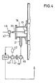
- FIG. 4 shows an exemplary embodiment in which the compressed air supplied to the atomizing nozzle 17 is generated by a volumetric pump or displacement pump 45.
- the positive displacement pump 45 is coupled via a clutch 46 to the output shaft 47 of the diesel engine DM (directly or via a gearbox).
- the fuel is also fed to the fuel line 20 via a positive displacement pump 48 which is driven by the output shaft 47 of the diesel engine. Since the quantities of compressed air and fuel both vary depending on the engine speed, but their mutual ratio remains constant, the mixture quantity is controlled in proportion to the speed. As a result, the burner output always adapts to the changed exhaust gas flow when the speed of the diesel engine varies. This means that the temperature at the filter can be kept largely constant during regeneration.
Landscapes
- Engineering & Computer Science (AREA)
- Chemical & Material Sciences (AREA)
- Combustion & Propulsion (AREA)
- Mechanical Engineering (AREA)
- General Engineering & Computer Science (AREA)
- Processes For Solid Components From Exhaust (AREA)
- Exhaust Gas After Treatment (AREA)
- Extrusion Moulding Of Plastics Or The Like (AREA)
- External Artificial Organs (AREA)
- Filtering Of Dispersed Particles In Gases (AREA)
Abstract
Aus dem Abgas eines Dieselmotors wird der Ruß mit einem keramischen Rußfilter 12 ausgefiltert. Zur Regenerierung des Rußfilters erfolgt ein Ausbrennen, mit Hilfe eines Brenners 16, der eine mit flüssigem Brennstoff und Luft versorgte Dralldüse 17 aufweist. Der Brenner wird mit einem überfetteten Brennstoff/Luft-Gemisch betrieben, und in der Hauptbrennkammer 15 wird eine stabile und rußfrei brennende Flamme erzeugt. Die Brenngase werden in einem Querstrommischer 39 mit den Abgasen vermischt und der restliche Brennstoffanteil verbrennt in einer Nachbrennkammer 37 durch die im Abgas enthaltene Luft. Die Regeneration kann während des Motorlaufes erfolgen, ohne daß der pulsierende Motordruck die Brennerflamme auslöscht. 
Description
Die Erfindung betrifft eine Rußfiltervorrichtung für einen Dieselmotor nach dem Oberbegriff des Patentanspruchs 1.The invention relates to a soot filter device for a diesel engine according to the preamble of patent claim 1.
Dieselmotoren produzieren bei bestimmten Lastfällen Ruß, der aus den Abgasen ausgefiltert werden sollte. In Erprobung sind keramische Rußfilter, die den Ruß von 5 bis 8 Stunden Fahrbetrieb aufnehmen können. Danach muß das Filter regeneriert werden. Die Regenerierung erfolgt durch Verbrennung der Rußpartikel mit hohen Abgastemperaturen von mindestens 600° C. Derartig hohe Abgastemperaturen sind bei Dieselmotoren wegen des hohen Luftüberschusses nicht vorhanden. Derzeit sind Verfahren in Erprobung, bei denen die Filtervorrichtung einen eigenen Brenner aufweist. Da dieser Brenner gegen den pulsierenden Abgasdruck des Dieselmotors nicht anarbeiten kann, sind Einrichtungen in Erprobung, bei denen während der Regeneration das Filter über einen zusätzlichen Schalldämpfer überbrückt wird.In certain load cases, diesel engines produce soot, which should be filtered out of the exhaust gases. Ceramic soot filters are being tested, which can absorb the soot from 5 to 8 hours of driving. The filter must then be regenerated. The regeneration is carried out by burning the soot particles with high exhaust gas temperatures of at least 600 ° C. Such high exhaust gas temperatures are not available in diesel engines due to the high excess air. Methods are currently being tested in which the filter device has its own burner. Because this burner does not counter the pulsating exhaust gas pressure of the diesel engine facilities are being tested, in which the filter is bridged by an additional silencer during regeneration.
Der Erfindung liegt die Aufgabe zugrunde, eine Rußfiltervorrichtung der im Oberbegriff des Patentanspruchs 1 angegebenen Art zu schaffen, bei der die Regeneration des Filters während des Betriebs des Dieselmotors ohne Umleitung der Motorabgase durchgeführt werden kann.The invention has for its object to provide a soot filter device of the type specified in the preamble of claim 1, in which the regeneration of the filter can be carried out during operation of the diesel engine without redirecting the engine exhaust.
Die Lösung dieser Aufgabe erfolgt erfindungsgemäß mit den im kennzeichnenden Teil des Patentanspruchs 1 angegebenen Merkmalen.This object is achieved according to the invention with the features specified in the characterizing part of patent claim 1.
Bei der erfindungsgemäßen Rußfiltervorrichtung erfolgt in der Hauptbrennkammer des Brenners eine nur teilweise Verbrennung des zugeführten Brennstoffs mit Hilfe von zwangsweise in einem bestimmten Mengenstrom zugeführter Luft, jedoch ohne Rußbildung. Der unverbrannte Teil des Brennstoffs wird zusammen mit den Brenngasen der Nachbrennkammer zugeführt, wo er durch den im Motorabgas enthaltenen Sauerstoff verbrennt. Der erste Teil der Verbrennung wird mit zugeführter externer Luft durchgeführt, und nur zur Nachverbrennung werden die Motorabgase benutzt. Da Druckluft nur für die Hauptverbrennung in unterstöchiometrischer Menge zugeführt wird, ist der Luftbedarf relativ gering.In the soot filter device according to the invention, only a partial combustion of the fuel supplied takes place in the main combustion chamber of the burner with the aid of air that is forcibly fed in a certain volume flow, but without soot formation. The unburned part of the fuel is fed together with the fuel gases to the afterburning chamber, where it burns due to the oxygen contained in the engine exhaust. The first part of the combustion is carried out with external air supplied, and the engine exhaust gases are used only for post-combustion. Since compressed air is only supplied in substoichiometric amounts for the main combustion, the air requirement is relatively low.
Die Zerstäuberdüse des Brenners ist vorzugsweise eine mit Drallelementen versehene Ringdüse. Diese Ringdüse weist eine ringförmige Zerstäuberzunge auf, an der innen Brennstoff entlangstreicht, der von dem rotierenden Luftstrom unter Bildung eines Strömungskegels feinzerstäubt wird. Eine zuverlässige stabile Verbrennung wird trotz pulsierendem Gegendruck und trotz Luftmangel durch Verwendung einer solchen "Luftzerstäuberdüse" erreicht. Wird die gesamte Luft für die Hauptverbrennung zugeführt mit einem Differenzdruck von mindestens 10 mbar, erhält man unmittelbar hinter der Düse eine intensive Mischung von feinem Brennstoffnebel mit der Verbrennungsluft. Zusammen mit der durch die Drallelemente der Zerstäuberdüse bewirkten Heißgasrezirkulation führt dieses zu einer von den Druckpulsationen unabhängigen Verbrennung.The atomizer nozzle of the burner is preferably an annular nozzle provided with swirl elements. This ring nozzle has an annular atomizing tongue, along which fuel passes along the inside, which is generated by the rotating air flow to form a flow cone is atomized. Reliable, stable combustion is achieved despite the pulsating back pressure and despite the lack of air by using such an "air atomizing nozzle". If all the air for the main combustion is supplied with a differential pressure of at least 10 mbar, an intensive mixture of fine fuel mist with the combustion air is obtained directly behind the nozzle. Together with the hot gas recirculation caused by the swirl elements of the atomizer nozzle, this leads to a combustion that is independent of the pressure pulsations.
Die dem Brenner zugeführte Druckluft kann dem Druckluftsystem des Fahrzeugs entnommen und über eine mit überkritischem Druckverhältnis betriebenen Düse der Zerstäuberdüse zugeführt werden. Überkritisches Druckverhältnis bedeutet, daß die Luft im engsten Düsenquerschnitt mindestens mit Schallgeschwindigkeit strömt. Damit kann eine von den Druckpulsationen des Motorabgases unabhängige Leistung des Brenners gefahren werden.The compressed air supplied to the burner can be taken from the compressed air system of the vehicle and fed to the atomizer nozzle via a nozzle operated with a supercritical pressure ratio. Supercritical pressure ratio means that the air flows in the narrowest nozzle cross-section at least at the speed of sound. A burner output that is independent of the pressure pulsations of the engine exhaust gas can thus be operated.
Alternativ kann die Verbrennungsluft durch ein Verdrängergebläse gefördert werden. Auch hierbei wird der Luftmassenstrom vom Gegendruck des Dieselabgasstroms nicht oder nur geringfügig beeinflußt, und es wird ein Brennerbetrieb mit vom pulsierenden Motordruck unbeeinflußtem Luftmengenstrom und damit unbeeinflußter Brennerleistung gewährleistet. Wenn man den Luftverdichter mit der Drehzahl des Dieselmotors koppelt und den Kraftstoff ebenfalls mit einer Verdrängerpumpe fördert, erhält man eine drehzahlproportionale Gemischmengensteuerung. Ändert sich die Drehzahl des Dieselmotors, so paßt sich die Brennerleistung dem veränderten Abgasmassenstrom an. Hierdurch kann die Temperatur am Filter während der Regeneration optimal eingehalten werden.Alternatively, the combustion air can be conveyed by a displacement fan. Here, too, the air mass flow is not or only slightly influenced by the back pressure of the diesel exhaust gas flow, and burner operation is ensured with an air flow rate unaffected by the pulsating engine pressure and thus unaffected burner output. If you couple the air compressor with the speed of the diesel engine and also deliver the fuel with a positive displacement pump, you get a speed-proportional mixture quantity control. If the speed of the diesel engine changes, the burner output adapts accordingly changed exhaust gas mass flow. This allows the temperature at the filter to be optimally maintained during regeneration.
Der Brenner ist so klein, daß er leicht in das Filtergehäuse eingebaut und durch einen Wärmeaustauscher mit dem Motorabgas gekühlt werden kann.The burner is so small that it can easily be installed in the filter housing and cooled with the engine exhaust gas by means of a heat exchanger.
Im folgenden werden unter Bezugnahme auf die Zeichnungen Ausführungsbeispiele der Erfindung näher erläutert.Exemplary embodiments of the invention are explained in more detail below with reference to the drawings.
Es zeigen:
- Fig. 1 einen schematischen Längsschnitt der Filtervorrichtung,
- Fig. 2 einen detailierten Längsschnitt durch die Zerstäuberdüse,
- Fig. 3 einen Schnitt entlang der Linie III-III von Fig. 2, und
- Fig. 4 ein anderes Beispiel der Luftversorgung der Zerstäuberdüse.
- 1 is a schematic longitudinal section of the filter device,
- 2 shows a detailed longitudinal section through the atomizing nozzle,
- Fig. 3 is a section along the line III-III of Fig. 2, and
- Fig. 4 shows another example of the air supply to the atomizer nozzle.
Die in Fig. 1 dargestellte Filtervorrichtung weist ein zylindrisches Gehäuse 10 auf. Das Gehäuse 10 hat an einem Ende einen radialen oder tangentialen Einlaß 11 für die Motorabgase und enthält ein den gesamten Gehäusequerschnitt einnehmendes Keramikfilter 12. Am anderen Ende des Gehäuses 10 befindet sich der Auslaßstutzen 13, durch den die Motorabgase und Brenngase aus dem Gehäuse austreten.The filter device shown in FIG. 1 has a
Der Abgaseinlaß 11 führt in eine ringförmige Verteilerkammer 14, die die Hauptbrennkammer 15 des Brenners 16 umgibt. Die Zerstäuberdüse 17 ist an der Deckelwand 18 des Düsengehäuses 19 angebracht. Diese Deckelwand 18 ist an die Stirnwand des Gehäuses 10 angeflanscht und begrenzt die Hauptbrennkammer 15. Die Brennstoffleitung 20 führt in das Düsengehäuse 19 hinein und ist direkt mit der Zerstäuberdüse 17 verbunden. Das Düsengehäuse 19 hat ferner einen Lufteinlaß 21, durch den Druckluft in das Innere des Düsengehäuses hineingepreßt wird. Wie Fig. 2 zeigt, führt die Brennstoffleitung 20 durch das Innere des Düsenkörpers 17a hindurch und tritt an dessen Stirnseite aus. Um das Ausstrittsrohr 20a herum, sind an der flanschartigen Stirnwand 22 des Düsenkörpers zahlreiche luftleitende Drallelemente 23 in Form von Flügeln angeordnet. Diese Drallelemente 23 sind gemäß Fig. 3 in Umfangsrichtung schräggestellt und sie verjüngen sich zum inneren Ende hin. Die Drallelemente 23 begrenzen Kanäle 24, durch die die radial einströmende Luft eine Umfangskomponente enthält. Jeder der Kanäle 24 verringert sich im Querschnitt zu seinem inneren Ende hin, so daß in jedem Kanal 24 die Luft zunehmend beschleunigt wird.The
Die Drallelemente 23 sind zwischen der Stirnwand 22 und einer parallel zu dieser Stirnwand verlaufenden Platte 25 angeordnet. Die den Drallelementen 23 abgewandte Stirnwand der Platte 25 bildet die Begrenzungswand eines weiteren Düsenraumes, der ebenfalls mit Drallelementen 26 ausgestattet ist, die an der Stirnseite einer weiteren Platte 27 angebracht sind. Die Platte 27 verläuft parallel zur Platte 25 und ihre Drallelemente 26 sind in gleicher weise ausgebildet und angeordnet wie die Drallelemente 23 der Platte 22.The
Die durch den Drucklufteinlaß 21 seitlich in das Düsengehäuse 19 einströmende Luft verteilt sich im Innern des Düsengehäuses und strömt radial in die Kanäle 24 zwischen den Drallelementen 23 sowie in die entsprechenden Kanäle zwischen den Drallelementen 26 ein. Durch die Drallelemente erhält die Luft einen Drall, d.h. eine kreisende Bewegung.The air flowing laterally into the
Die Platte 25 ist ringförmig ausgebildet und ihr innerer Rand hat die Form einer in Strömungsrichtung axial abstehenden, ringförmigen, sich zum Ende hin konisch verjüngenden Schneide 29. Auch die innere Kante der ringförmigen Platte 27 ist in Strömungsrichtung axial umgebogen und sie bildet einen konischen Ring 30, der die Schneide 29 mit radialem Abstand umgibt.The
Der aus dem Rohr 20a austretende flüssige Brennstoff wird von dem rotierenden Luftstrom erfaßt und auf die Innenseite der Schneide 29 aufgesprüht. Die Schneide 29 wird zu beiden Seiten von rotierenden und sich axial bewegenden Luftströmen umströmt, die den Brennstoff von der kreisförmigen scharfen Spitze der Schneide 29 abreißen und ihn fein und gleichmäßig in Tröpfchenform verteilen. Die Brennstofftröpfchen vermischen sich dabei mit der Verbrennungsluft und treten zusammen mit dieser in die rohrförmige Hauptbrennkammer 15 ein. Infolge der Drallinjektion unter hohem Druck entstehen, in der Hauptbrennkammer 15 ringförmige Strömungswalzen, in denen ein Teil des Gemischstroms zurückgeführt wird, und die um die Längsachse herum rotieren. Zum Zünden des Gemisches ist in der Hauptbrennkammer 15 eine Elektrode 31 angeordnet.The liquid fuel emerging from the
Die Hauptbrennkammer 15 ist an dem der Zerstäuberdüse 17 abgewandten Ende durch eine Ringwand 32 begrenzt, die eine Öffnung 33 für den Austritt der Brenngase bildet. Im Abstand hinter der Ringwand 32 befindet sich eine Stirnwand 34, die den hinter der Hauptbrennkammer 15 liegenden Raum 35 begrenzt. An der Umfangswand der Außenseite der Hauptbrennkammer 15 verlaufen Wärmetauscherrippen 36, die sich bis zur Stirnwand 34 erstrecken. Zwischen diesen Wärmetauscherrippen 36 strömen die Brenngase radial aus dem Raum 35 heraus in die Nachbrennkammer 37, die an einem Ende durch das Filter 12 begrenzt wird.The
Von der Verteilerkammer 14 führt ein ringförmiger Durchlaß 38 zu den Wärmetauscherrippen 36. Die Motorabgase strömen durch den Durchlaß 38 hindurch, an den Wärmetauscherrippen 36 entlang, und werden dann mit den Verbrennungsgasen vermischt, um mit diesen gemeinsam in die Nachbrennkammer 37 einzuströmen. Von dort strömt das heiße Gasgemisch durch das Filter 12 zum Auslaßstutzen 13.An
Die Kammer 35 bildet an ihrem Umfang einen Querstrommischer 39, in dem eine intensive Mischung der Gasströme stattfindet.The
Der Drucklufteinlaß 21 enthält eine kritisch durchströmte Düse 40, die über ein Schaltventil 41 an den Druckluftsammler 42 des Dieselmotors DM angeschlossen ist. Die Abtriebswelle des Dieselmotors treibt (direkt oder über eine Untersetzung) ein Gebläse 43, das den Druckluftsammler 42 speist.The
Wenn das Ventil 41 geöffnet ist und Brennstoff in die Brennstoffleitung 20 gepumpt wird, gelangen Brennstoff und Luft zur Zerstäuberdüse 17. Durch den in der Zerstäuberdüse 17 aufgeprägten Drall stabilisiert sich die Flamme und brennt trotz der unterstöchiometrischen Luftmenge rußfrei. Das Abgas des Motors gelangt über den Einlaß 11 und die Verteilerkammer 14 zwischen die Wärmetauscherrippen 36, um die Wand der Hauptbrennkammer 15 zu kühlen. Nach dem Vermischen von Motorabgas und Verbrennungsgas im Querstrommischer 39 erfolgt das Ausbrennen der Flamme mit Hilfe des im Abgas enthaltenen Restsauerstoffs in der nach Brennkammer 37. Das so aufgeheizte Gas strömt durch das keramische Filter 12 und brennt den Ruß ab.When the
Fig. 4 zeigt ein Ausführungsbeispiel, bei dem die der Zerstäuberdüse 17 zugeführte Druckluft von einer volumetrischen Pumpe oder Verdrängerpumpe 45 erzeugt wird. Die Verdrängerpumpe 45 ist über eine Kupplung 46, mit der Abtriebswelle 47 des Dieselmotors DM (direkt oder über ein Getriebe) gekuppelt. Der Brennstoff wird der Brennstoffleitung 20 ebenfalls über eine Verdrängerpumpe 48 zugeführt, die von der Abtriebswelle 47 des Dieselmotors angetrieben ist. Da die Mengen von Druckluft und Brennstoff beide in Abhängigkeit von der Motordrehzahl variieren, ihr gegenseitiges Verhältnis aber konstant bleibt, erfolgt eine drehzahlproportionale Gemischmengensteuerung. Dadurch paßt sich die Brennerleistung bei variierender Drehzahl des Dieselmotors immer dem veränderten Abgasmengenstrom an. Dadurch kann die Temperatur am Filter während der Regeneration weitgehend konstant gehalten werden.FIG. 4 shows an exemplary embodiment in which the compressed air supplied to the
Claims (8)
dadurch gekennzeichnet,
daß der Luftstromzerstäuberdüse (17) Druckluft im Verhältnis zum Brennstoff unterstöchiometrisch in konstantem Mengenstrom zugeführt wird, daß der Brennraum in eine sich an die Luftstromzerstäuberdüse (17) anschließende Hauptbrennkammer (15) und eine dahinter angeordnete Nachbrennkammer (37) unterteilt ist und daß die Abgase des Dieselmotors zur Nachverbrennung des Brennstoffs in die Nachbrennkammer (37) eingeleitet werden.1. A soot filter device for a diesel engine, with a filter (12) connected to the exhaust pipe and a burner (16) for burning the filter, the burner (16) having an atomizing nozzle (17) for fuel and a combustion chamber,
characterized by
that the airflow atomizer nozzle (17) compressed air in relation to the fuel is supplied substoichiometrically in a constant flow, that the combustion chamber is divided into a main combustion chamber (15) adjoining the airflow atomizer nozzle (17) and an afterburner chamber (37) arranged behind it, and that the exhaust gases of the Diesel engine for post-combustion of the fuel can be introduced into the post-combustion chamber (37).
dadurch gekennzeichnet,
daß die Hauptbrennkammer (15) durch eine Ringwand (32) begrenzt ist.2. soot filter device according to claim 1,
characterized by
that the main combustion chamber (15) is delimited by an annular wall (32).
dadurch gekennzeichnet,
daß die Hauptbrennkammer (15) von einem Wärmetauscher (36) umgeben ist, den die Abgase vor Erreichen der Nachbrennkammer (37) durchströmen.3. soot filter device according to claim 1 or 2,
characterized by
that the main combustion chamber (15) is surrounded by a heat exchanger (36) through which the exhaust gases flow before reaching the afterburning chamber (37).
dadurch gekennzeichnet,
daß hinter der Hauptbrennkammer (15) ein Querstrommischer (39) angeordnet ist, der von den Abgasen des Brenners radial und von den Abgasen des Motors axial durchströmt wird.4. soot filter device according to one of claims 1 to 3,
characterized by
that a cross-flow mixer (39) is arranged behind the main combustion chamber (15), through which the exhaust gases of the burner flow radially and the exhaust gases of the engine flow axially.
dadurch gekennzeichnet,
daß die Zerstäuberdüse (17) eine mit Drallelementen (23,26) versehene Luftstromzerstäuberdüse ist.5. soot filter device according to one of claims 1 to 4,
characterized by
that the atomizer nozzle (17) is an air flow atomizer nozzle provided with swirl elements (23, 26).
dadurch gekennzeichnet,
daß die Druckluft dem Druckluftsystem des Fahrzeugs entnommen und über eine bei kritischem Druckverhältnis betriebene Düse (40) der Zerstäuberdüse (17) zugeführt wird.6. soot filter device according to one of claims 1 to 5,
characterized by
that the compressed air is removed from the compressed air system of the vehicle and fed to the atomizing nozzle (17) via a nozzle (40) operated at a critical pressure ratio.
dadurch gekennzeichnet,
daß die Druckluft von einem Verdrängergebläse (43) erzeugt wird.7. soot filter device according to one of claims 1 to 5,
characterized by
that the compressed air is generated by a displacement fan (43).
dadurch gekennzeichnet,
daß der Brenner (16), zusammen mit dem Filter (12), im selben Gehäuse (10) angeordnet ist.8. soot filter device according to one of claims 1 to 7,
characterized by
that the burner (16), together with the filter (12), is arranged in the same housing (10).
Priority Applications (1)
| Application Number | Priority Date | Filing Date | Title |
|---|---|---|---|
| AT88113462T ATE81887T1 (en) | 1987-09-05 | 1988-08-19 | SOOT FILTER METHOD AND SOOT FILTER DEVICE FOR A DIESEL ENGINE. |
Applications Claiming Priority (2)
| Application Number | Priority Date | Filing Date | Title |
|---|---|---|---|
| DE3729861A DE3729861C2 (en) | 1987-09-05 | 1987-09-05 | Method for operating a soot filter device for a diesel engine and soot filter device for carrying out this method |
| DE3729861 | 1987-09-05 |
Publications (3)
| Publication Number | Publication Date |
|---|---|
| EP0306743A2 true EP0306743A2 (en) | 1989-03-15 |
| EP0306743A3 EP0306743A3 (en) | 1990-01-31 |
| EP0306743B1 EP0306743B1 (en) | 1992-10-28 |
Family
ID=6335373
Family Applications (1)
| Application Number | Title | Priority Date | Filing Date |
|---|---|---|---|
| EP88113462A Expired - Lifetime EP0306743B1 (en) | 1987-09-05 | 1988-08-19 | Soot filter process and soot filter device for a diesel engine |
Country Status (8)
| Country | Link |
|---|---|
| US (1) | US4951464A (en) |
| EP (1) | EP0306743B1 (en) |
| JP (1) | JP2559620B2 (en) |
| AT (1) | ATE81887T1 (en) |
| CA (1) | CA1336966C (en) |
| DE (2) | DE3729861C2 (en) |
| FI (1) | FI102629B (en) |
| GR (1) | GR3006690T3 (en) |
Cited By (17)
| Publication number | Priority date | Publication date | Assignee | Title |
|---|---|---|---|---|
| EP0367280A1 (en) * | 1988-11-04 | 1990-05-09 | Klöckner-Humboldt-Deutz Aktiengesellschaft | Particle filter system |
| EP0438682A3 (en) * | 1990-01-25 | 1992-02-26 | Man Technologie Aktiengesellschaft | Exhaust system with particle filter and regeneration burner |
| EP0331795B1 (en) * | 1988-03-09 | 1992-03-18 | Webasto AG Fahrzeugtechnik | Burner operated by the exhaust gas of an internal combustion engine |
| EP0532044A1 (en) * | 1991-09-12 | 1993-03-17 | Firma J. Eberspächer | Burner for a diesel engine exhaust particle filter |
| EP0532031A1 (en) * | 1991-09-12 | 1993-03-17 | Firma J. Eberspächer | Device for the thermal regeneration of diesel engine exhaust particle filters |
| TR25558A (en) * | 1990-08-07 | 1993-07-01 | Man Technologie Gmbh | WASTE GAS PIPE WITH A REGENERATION BURNER WITH A PARTICLE FILTER |
| EP0554499A1 (en) * | 1992-02-01 | 1993-08-11 | ERNST-APPARATEBAU GmbH & Co. | Soot filter with a ring chamber |
| US5320523A (en) * | 1992-08-28 | 1994-06-14 | General Motors Corporation | Burner for heating gas stream |
| EP0583507B1 (en) * | 1992-08-14 | 1996-03-27 | ERNST APPARATEBAU GmbH & Co. | Soot filter with hot gas generator |
| EP1752633A1 (en) * | 2005-08-11 | 2007-02-14 | Deutsches Zentrum für Luft- und Raumfahrt e.V. | Device for generating a hot gas in an exhaust system of an combustion engine |
| EP1939419A1 (en) | 2006-12-19 | 2008-07-02 | J. Eberspächer GmbH & Co. KG | Exhaust system for an internal combustion engine |
| WO2023242029A1 (en) * | 2022-06-13 | 2023-12-21 | Mercedes-Benz Group AG | Burner for a motor vehicle, and motor vehicle comprising at least one such burner |
| WO2023242031A1 (en) * | 2022-06-13 | 2023-12-21 | Mercedes-Benz Group AG | Burner for a motor vehicle, and motor vehicle comprising at least one such burner |
| WO2023241907A1 (en) * | 2022-06-13 | 2023-12-21 | Mercedes-Benz Group AG | Burner for a motor vehicle, and motor vehicle comprising at least one such burner |
| WO2023242030A1 (en) * | 2022-06-13 | 2023-12-21 | Mercedes-Benz Group AG | Burner for a motor vehicle, method for operating such a burner, and motor vehicle |
| WO2024104671A1 (en) * | 2022-11-14 | 2024-05-23 | Robert Bosch Gmbh | Burner unit in exhaust tract of an internal combustion engine |
| DE102023209182A1 (en) * | 2023-09-20 | 2025-03-20 | Friedrich Boysen Gmbh & Co. Kg | Exhaust gas burner and exhaust gas aftertreatment system |
Families Citing this family (50)
| Publication number | Priority date | Publication date | Assignee | Title |
|---|---|---|---|---|
| DE4015013B4 (en) * | 1990-05-10 | 2004-09-16 | Deutz Ag | mixing device |
| DE4038064A1 (en) * | 1990-11-29 | 1992-06-04 | Kloeckner Humboldt Deutz Ag | Burner for liq. fuel - works with torsion nozzle and combustion chamber, regenerating combustion particle filters and includes flow rectifier |
| US5339630A (en) * | 1992-08-28 | 1994-08-23 | General Motors Corporation | Exhaust burner catalyst preheater |
| DE4242091C2 (en) * | 1992-12-14 | 2002-11-07 | Deutz Ag | Device for starting the regeneration burner of a particle filter system at low temperatures |
| DE4242096B4 (en) * | 1992-12-14 | 2004-03-25 | Deutz Ag | Purge air supply to a particle filter system |
| DE4242094B4 (en) * | 1992-12-14 | 2004-09-02 | Deutz Ag | Regeneration burner with integral construction of its valve housing and combustion chamber |
| DE4242090A1 (en) * | 1992-12-14 | 1994-06-16 | Kloeckner Humboldt Deutz Ag | Method to operate particle filter system - involves oxygen deficiency occurring in exhaust gas of engine being made up by increasing combustion air volume |
| DE4242093C2 (en) * | 1992-12-14 | 2003-05-22 | Deutz Ag | Function monitoring of a particle filter system |
| DE4242095C2 (en) * | 1992-12-14 | 1996-10-31 | Kloeckner Humboldt Deutz Ag | Process for reducing pollutant emissions from diesel engines and a particle filter system for its implementation |
| DE4303720C2 (en) * | 1993-02-09 | 2003-12-24 | Deutz Ag | particulate filter system |
| DE4307525A1 (en) * | 1993-03-10 | 1994-09-15 | Audi Ag | Method and device for the treatment of exhaust gases from an internal combustion engine |
| DE4440716C2 (en) * | 1994-11-15 | 1997-02-27 | Daimler Benz Ag | Soot filter system for internal combustion engines |
| DE19729246C2 (en) | 1997-07-09 | 2001-06-28 | Deutsch Zentr Luft & Raumfahrt | Atomizer nozzle for atomizing fuel in burners |
| SE525197C2 (en) * | 2003-06-18 | 2004-12-21 | Volvo Lastvagnar Ab | Apparatus for controlling the temperature of exhaust gases from an exhaust system equipped with an active regenerable filter |
| US20060218902A1 (en) * | 2005-03-31 | 2006-10-05 | Solar Turbines Incorporated | Burner assembly for particulate trap regeneration |
| US7406822B2 (en) * | 2005-06-30 | 2008-08-05 | Caterpillar Inc. | Particulate trap regeneration system and control strategy |
| US7481048B2 (en) * | 2005-06-30 | 2009-01-27 | Caterpillar Inc. | Regeneration assembly |
| US20070158466A1 (en) * | 2005-12-29 | 2007-07-12 | Harmon Michael P | Nozzle assembly |
| US20070228191A1 (en) * | 2006-03-31 | 2007-10-04 | Caterpillar Inc. | Cooled nozzle assembly for urea/water injection |
| US20070235556A1 (en) * | 2006-03-31 | 2007-10-11 | Harmon Michael P | Nozzle assembly |
| DE102006015841B3 (en) * | 2006-04-03 | 2007-08-02 | TWK Engineering Entwicklungstechnik (GbR) (vertretungsberechtigte Gesellschafter Herrn Thomas Winter, Jagdhaus am Breitenberg, 56244 Ötzingen und Herrn Waldemar Karsten, Am Merzenborn 6, 56422 Wirges) | Regeneration of particle filters comprises burning fuel under oxygen deficiency in first combustion chamber, and introducing gas produced to second chamber where air current is produced flowing in direction counter to direction of gas flow |
| US7874148B2 (en) * | 2007-03-15 | 2011-01-25 | Deere & Company | Regeneration system and method for particulate traps |
| US20080264046A1 (en) * | 2007-04-30 | 2008-10-30 | Caterpillar Inc. | Regeneration device having air-assisted fuel nozzle |
| US8459017B2 (en) | 2008-04-09 | 2013-06-11 | Woodward, Inc. | Low pressure drop mixer for radial mixing of internal combustion engine exhaust flows, combustor incorporating same, and methods of mixing |
| JP5246005B2 (en) * | 2009-04-15 | 2013-07-24 | 株式会社Ihi | Burner equipment |
| US20110289906A1 (en) * | 2009-04-27 | 2011-12-01 | Nicholas Morley | Miniature Regeneration Unit |
| JP4720935B2 (en) | 2009-07-14 | 2011-07-13 | 株式会社Ihi | Burner equipment |
| JP5353822B2 (en) * | 2009-09-30 | 2013-11-27 | 株式会社Ihi | Ignition device |
| US9506385B2 (en) | 2010-07-15 | 2016-11-29 | Faurecia Emissions Control Technologies, Usa, Llc | Fuel fired burner for vehicle exhaust component |
| US8938954B2 (en) | 2012-04-19 | 2015-01-27 | Donaldson Company, Inc. | Integrated exhaust treatment device having compact configuration |
| US8991163B2 (en) | 2013-02-27 | 2015-03-31 | Tenneco Automotive Operating Company Inc. | Burner with air-assisted fuel nozzle and vaporizing ignition system |
| US9027331B2 (en) | 2013-02-27 | 2015-05-12 | Tenneco Automotive Operating Company Inc. | Exhaust aftertreatment burner with preheated combustion air |
| US8959902B2 (en) * | 2013-02-27 | 2015-02-24 | Tenneco Automotive Operating Company Inc. | Exhaust treatment burner and mixer system |
| US9027332B2 (en) | 2013-02-27 | 2015-05-12 | Tenneco Automotive Operating Company Inc. | Ion sensor with decoking heater |
| US9352276B2 (en) | 2013-05-07 | 2016-05-31 | Tenneco Automotive Operating Company Inc. | Exhaust mixing device |
| US9334781B2 (en) | 2013-05-07 | 2016-05-10 | Tenneco Automotive Operating Company Inc. | Vertical ultrasonic decomposition pipe |
| US9291081B2 (en) | 2013-05-07 | 2016-03-22 | Tenneco Automotive Operating Company Inc. | Axial flow atomization module |
| US9314750B2 (en) | 2013-05-07 | 2016-04-19 | Tenneco Automotive Operating Company Inc. | Axial flow atomization module |
| US9364790B2 (en) | 2013-05-07 | 2016-06-14 | Tenneco Automotive Operating Company Inc. | Exhaust mixing assembly |
| US9289724B2 (en) | 2013-05-07 | 2016-03-22 | Tenneco Automotive Operating Company Inc. | Flow reversing exhaust gas mixer |
| US9534525B2 (en) | 2015-05-27 | 2017-01-03 | Tenneco Automotive Operating Company Inc. | Mixer assembly for exhaust aftertreatment system |
| DE102021001584B4 (en) | 2021-03-25 | 2024-03-07 | Mercedes-Benz Group AG | Burner for a motor vehicle |
| DE102021001585B4 (en) | 2021-03-25 | 2024-08-22 | DVGW Deutscher Verein des Gas- und Wasserfaches e.V. - Technisch-wissenschaftlicher Verein | Burner for an exhaust system of a motor vehicle and motor vehicle |
| DE102021001581B4 (en) | 2021-03-25 | 2024-03-07 | Mercedes-Benz Group AG | Burner for a motor vehicle and motor vehicle |
| DE102021001580A1 (en) | 2021-03-25 | 2022-09-29 | Mercedes-Benz Group AG | Burner for a motor vehicle and motor vehicle with at least one such burner |
| DE102022002112A1 (en) | 2022-06-13 | 2023-12-14 | Mercedes-Benz Group AG | Burner for a motor vehicle and motor vehicle with at least one such burner |
| DE102022002114B4 (en) | 2022-06-13 | 2024-01-11 | Mercedes-Benz Group AG | Burner for a motor vehicle and motor vehicle with at least one such burner |
| DE102022002118B3 (en) | 2022-06-13 | 2023-09-21 | Mercedes-Benz Group AG | Burner for a motor vehicle and motor vehicle with at least one such burner |
| DE102023000324A1 (en) | 2023-02-03 | 2024-08-08 | Mercedes-Benz Group AG | Burner for an exhaust system of an internal combustion engine, in particular of a motor vehicle, method for operating such a burner and internal combustion engine for a motor vehicle |
| DE102023003068B3 (en) | 2023-07-26 | 2024-12-12 | Mercedes-Benz Group AG | Burner for a motor vehicle and motor vehicle with at least one such burner |
Family Cites Families (9)
| Publication number | Priority date | Publication date | Assignee | Title |
|---|---|---|---|---|
| US3703259A (en) * | 1971-05-03 | 1972-11-21 | Gen Electric | Air blast fuel atomizer |
| DE3219948A1 (en) * | 1982-05-27 | 1983-12-01 | Bayerische Motoren Werke AG, 8000 München | BURNER FOR A SOOT FILTER OF INTERNAL COMBUSTION ENGINES |
| JPS5939915A (en) * | 1982-08-27 | 1984-03-05 | Mazda Motor Corp | Exhaust gas purifying device for diesel engine |
| JPS5943621U (en) * | 1982-09-13 | 1984-03-22 | マツダ株式会社 | Diesel engine exhaust gas purification device |
| JPS5988209U (en) * | 1982-12-04 | 1984-06-14 | マツダ株式会社 | Diesel engine exhaust gas purification device |
| JPS59100917U (en) * | 1982-12-24 | 1984-07-07 | 日産自動車株式会社 | Internal combustion engine exhaust particulate treatment device |
| JPS59153914A (en) * | 1983-02-21 | 1984-09-01 | Nissan Motor Co Ltd | Regenerative burner control device in exhaust particle trap in internal-combustion engine |
| JPH0627500B2 (en) * | 1983-07-29 | 1994-04-13 | 三菱自動車工業株式会社 | Diesel particulate filter-regeneration device |
| US4651524A (en) * | 1984-12-24 | 1987-03-24 | Arvin Industries, Inc. | Exhaust processor |
-
1987
- 1987-09-05 DE DE3729861A patent/DE3729861C2/en not_active Expired - Lifetime
-
1988
- 1988-08-19 EP EP88113462A patent/EP0306743B1/en not_active Expired - Lifetime
- 1988-08-19 DE DE8888113462T patent/DE3875568D1/en not_active Expired - Lifetime
- 1988-08-19 AT AT88113462T patent/ATE81887T1/en not_active IP Right Cessation
- 1988-09-01 FI FI884045A patent/FI102629B/en not_active IP Right Cessation
- 1988-09-02 US US07/240,270 patent/US4951464A/en not_active Expired - Lifetime
- 1988-09-02 CA CA000576502A patent/CA1336966C/en not_active Expired - Fee Related
- 1988-09-05 JP JP22218488A patent/JP2559620B2/en not_active Expired - Fee Related
-
1992
- 1992-12-28 GR GR920403154T patent/GR3006690T3/el unknown
Cited By (19)
| Publication number | Priority date | Publication date | Assignee | Title |
|---|---|---|---|---|
| EP0331795B1 (en) * | 1988-03-09 | 1992-03-18 | Webasto AG Fahrzeugtechnik | Burner operated by the exhaust gas of an internal combustion engine |
| EP0367280A1 (en) * | 1988-11-04 | 1990-05-09 | Klöckner-Humboldt-Deutz Aktiengesellschaft | Particle filter system |
| EP0438682A3 (en) * | 1990-01-25 | 1992-02-26 | Man Technologie Aktiengesellschaft | Exhaust system with particle filter and regeneration burner |
| TR25558A (en) * | 1990-08-07 | 1993-07-01 | Man Technologie Gmbh | WASTE GAS PIPE WITH A REGENERATION BURNER WITH A PARTICLE FILTER |
| EP0532044A1 (en) * | 1991-09-12 | 1993-03-17 | Firma J. Eberspächer | Burner for a diesel engine exhaust particle filter |
| EP0532031A1 (en) * | 1991-09-12 | 1993-03-17 | Firma J. Eberspächer | Device for the thermal regeneration of diesel engine exhaust particle filters |
| EP0554499A1 (en) * | 1992-02-01 | 1993-08-11 | ERNST-APPARATEBAU GmbH & Co. | Soot filter with a ring chamber |
| EP0583507B1 (en) * | 1992-08-14 | 1996-03-27 | ERNST APPARATEBAU GmbH & Co. | Soot filter with hot gas generator |
| US5320523A (en) * | 1992-08-28 | 1994-06-14 | General Motors Corporation | Burner for heating gas stream |
| EP1752633A1 (en) * | 2005-08-11 | 2007-02-14 | Deutsches Zentrum für Luft- und Raumfahrt e.V. | Device for generating a hot gas in an exhaust system of an combustion engine |
| EP1939419A1 (en) | 2006-12-19 | 2008-07-02 | J. Eberspächer GmbH & Co. KG | Exhaust system for an internal combustion engine |
| US8006487B2 (en) | 2006-12-19 | 2011-08-30 | J. Eberspaecher Gmbh & Co. Kg | Exhaust system for an internal combustion engine |
| WO2023242029A1 (en) * | 2022-06-13 | 2023-12-21 | Mercedes-Benz Group AG | Burner for a motor vehicle, and motor vehicle comprising at least one such burner |
| WO2023242031A1 (en) * | 2022-06-13 | 2023-12-21 | Mercedes-Benz Group AG | Burner for a motor vehicle, and motor vehicle comprising at least one such burner |
| WO2023241907A1 (en) * | 2022-06-13 | 2023-12-21 | Mercedes-Benz Group AG | Burner for a motor vehicle, and motor vehicle comprising at least one such burner |
| WO2023242030A1 (en) * | 2022-06-13 | 2023-12-21 | Mercedes-Benz Group AG | Burner for a motor vehicle, method for operating such a burner, and motor vehicle |
| WO2024104671A1 (en) * | 2022-11-14 | 2024-05-23 | Robert Bosch Gmbh | Burner unit in exhaust tract of an internal combustion engine |
| DE102023209182A1 (en) * | 2023-09-20 | 2025-03-20 | Friedrich Boysen Gmbh & Co. Kg | Exhaust gas burner and exhaust gas aftertreatment system |
| DE102023209182B4 (en) * | 2023-09-20 | 2025-05-08 | Friedrich Boysen Gmbh & Co. Kg | Exhaust gas burner and exhaust gas aftertreatment system |
Also Published As
| Publication number | Publication date |
|---|---|
| GR3006690T3 (en) | 1993-06-30 |
| JPS6483810A (en) | 1989-03-29 |
| FI102629B1 (en) | 1999-01-15 |
| CA1336966C (en) | 1995-09-12 |
| ATE81887T1 (en) | 1992-11-15 |
| FI102629B (en) | 1999-01-15 |
| DE3729861C2 (en) | 1995-06-22 |
| FI884045A7 (en) | 1989-03-06 |
| FI884045A0 (en) | 1988-09-01 |
| DE3729861A1 (en) | 1989-03-16 |
| US4951464A (en) | 1990-08-28 |
| DE3875568D1 (en) | 1992-12-03 |
| EP0306743A3 (en) | 1990-01-31 |
| JP2559620B2 (en) | 1996-12-04 |
| EP0306743B1 (en) | 1992-10-28 |
Similar Documents
| Publication | Publication Date | Title |
|---|---|---|
| EP0306743B1 (en) | Soot filter process and soot filter device for a diesel engine | |
| EP0367280B2 (en) | Particle filter system | |
| DE69214154T2 (en) | LOW-EMISSION BURNER NOZZLE FOR GAS TURBINE SYSTEM | |
| DE69412484T2 (en) | COMBUSTION CHAMBER OF A GAS TURBINE ENGINE | |
| DE69419156T2 (en) | INJECTION NOZZLE AND METHOD FOR OPERATING THE SAME | |
| DE3889539T2 (en) | GAS TURBINE COMBUSTION CHAMBER WITH TANGENTIAL FUEL INJECTION AND ADDITIONAL FUEL JETS. | |
| DE69414107T2 (en) | RADIAL AIR COMPRESSOR INJECTOR FOR FUEL | |
| DE3532778C2 (en) | ||
| DE19750329A1 (en) | Fuel injection device with input feed conduit for liquid precombustion fuel | |
| EP0571782A1 (en) | Gasturbine combustor and operating method | |
| EP0631039B1 (en) | Burner for heating up an exhaust catalyst quickly and independently of the engine | |
| DE10205573B4 (en) | Atomizing nozzle for a burner | |
| DE3741021C2 (en) | Combustion chamber for a gas turbine engine | |
| DE4440716A1 (en) | Diesel engine soot filter with burner and flame tube | |
| DE3608698A1 (en) | BURNER BOILER UNIT | |
| DE2849945C2 (en) | Exhaust gas turbocharger for an internal combustion engine | |
| DE69019538T2 (en) | Gas turbine with an injector for gaseous fuel and an injector for such a gas turbine. | |
| DE2165172A1 (en) | Radiant heating tube for industrial furnaces | |
| DE4325906C2 (en) | Device for the regeneration of a particle filter used in the exhaust tract of an internal combustion engine | |
| EP1752633B1 (en) | Device for generating a hot gas in an exhaust system of a combustion engine | |
| DE2160675C3 (en) | Burner device for a gas turbine combustion chamber | |
| DE2364053A1 (en) | METHOD AND DEVICE FOR BURNING FUEL | |
| DE2252358C3 (en) | Liquid fuel burners | |
| DE3132866C2 (en) | Burner for burning a liquid combustible medium containing pollutants | |
| DE10254664B3 (en) | Liquid fuel burner has housing with support pipe, combustion chamber, fuel jet, separating element with central opening, current recirculating and stabilizing parts |
Legal Events
| Date | Code | Title | Description |
|---|---|---|---|
| PUAI | Public reference made under article 153(3) epc to a published international application that has entered the european phase |
Free format text: ORIGINAL CODE: 0009012 |
|
| AK | Designated contracting states |
Kind code of ref document: A2 Designated state(s): AT CH DE FR GB GR IT LI NL SE |
|
| RAP1 | Party data changed (applicant data changed or rights of an application transferred) |
Owner name: DEUTSCHE FORSCHUNGSANSTALT FUER LUFT- UND RAUMFAHR |
|
| PUAL | Search report despatched |
Free format text: ORIGINAL CODE: 0009013 |
|
| AK | Designated contracting states |
Kind code of ref document: A3 Designated state(s): AT CH DE FR GB GR IT LI NL SE |
|
| 17P | Request for examination filed |
Effective date: 19891228 |
|
| 17Q | First examination report despatched |
Effective date: 19910402 |
|
| GRAA | (expected) grant |
Free format text: ORIGINAL CODE: 0009210 |
|
| AK | Designated contracting states |
Kind code of ref document: B1 Designated state(s): AT CH DE FR GB GR IT LI NL SE |
|
| REF | Corresponds to: |
Ref document number: 81887 Country of ref document: AT Date of ref document: 19921115 Kind code of ref document: T |
|
| ITF | It: translation for a ep patent filed | ||
| ET | Fr: translation filed | ||
| GBT | Gb: translation of ep patent filed (gb section 77(6)(a)/1977) | ||
| REF | Corresponds to: |
Ref document number: 3875568 Country of ref document: DE Date of ref document: 19921203 |
|
| REG | Reference to a national code |
Ref country code: GR Ref legal event code: FG4A Free format text: 3006690 |
|
| PLBE | No opposition filed within time limit |
Free format text: ORIGINAL CODE: 0009261 |
|
| STAA | Information on the status of an ep patent application or granted ep patent |
Free format text: STATUS: NO OPPOSITION FILED WITHIN TIME LIMIT |
|
| 26N | No opposition filed | ||
| EAL | Se: european patent in force in sweden |
Ref document number: 88113462.1 |
|
| REG | Reference to a national code |
Ref country code: GB Ref legal event code: IF02 |
|
| PGFP | Annual fee paid to national office [announced via postgrant information from national office to epo] |
Ref country code: GB Payment date: 20050808 Year of fee payment: 18 |
|
| PGFP | Annual fee paid to national office [announced via postgrant information from national office to epo] |
Ref country code: NL Payment date: 20050818 Year of fee payment: 18 |
|
| PGFP | Annual fee paid to national office [announced via postgrant information from national office to epo] |
Ref country code: FR Payment date: 20050819 Year of fee payment: 18 |
|
| PGFP | Annual fee paid to national office [announced via postgrant information from national office to epo] |
Ref country code: AT Payment date: 20050823 Year of fee payment: 18 |
|
| PGFP | Annual fee paid to national office [announced via postgrant information from national office to epo] |
Ref country code: SE Payment date: 20050824 Year of fee payment: 18 |
|
| PGFP | Annual fee paid to national office [announced via postgrant information from national office to epo] |
Ref country code: GR Payment date: 20050830 Year of fee payment: 18 |
|
| PG25 | Lapsed in a contracting state [announced via postgrant information from national office to epo] |
Ref country code: AT Free format text: LAPSE BECAUSE OF NON-PAYMENT OF DUE FEES Effective date: 20060819 |
|
| PG25 | Lapsed in a contracting state [announced via postgrant information from national office to epo] |
Ref country code: SE Free format text: LAPSE BECAUSE OF NON-PAYMENT OF DUE FEES Effective date: 20060820 |
|
| PGFP | Annual fee paid to national office [announced via postgrant information from national office to epo] |
Ref country code: IT Payment date: 20060831 Year of fee payment: 19 |
|
| PG25 | Lapsed in a contracting state [announced via postgrant information from national office to epo] |
Ref country code: NL Free format text: LAPSE BECAUSE OF NON-PAYMENT OF DUE FEES Effective date: 20070301 |
|
| EUG | Se: european patent has lapsed | ||
| GBPC | Gb: european patent ceased through non-payment of renewal fee |
Effective date: 20060819 |
|
| NLV4 | Nl: lapsed or anulled due to non-payment of the annual fee |
Effective date: 20070301 |
|
| REG | Reference to a national code |
Ref country code: FR Ref legal event code: ST Effective date: 20070430 |
|
| PGFP | Annual fee paid to national office [announced via postgrant information from national office to epo] |
Ref country code: DE Payment date: 20070727 Year of fee payment: 20 |
|
| PG25 | Lapsed in a contracting state [announced via postgrant information from national office to epo] |
Ref country code: GB Free format text: LAPSE BECAUSE OF NON-PAYMENT OF DUE FEES Effective date: 20060819 |
|
| PGFP | Annual fee paid to national office [announced via postgrant information from national office to epo] |
Ref country code: CH Payment date: 20070827 Year of fee payment: 20 |
|
| PG25 | Lapsed in a contracting state [announced via postgrant information from national office to epo] |
Ref country code: FR Free format text: LAPSE BECAUSE OF NON-PAYMENT OF DUE FEES Effective date: 20060831 |
|
| REG | Reference to a national code |
Ref country code: CH Ref legal event code: PL |
|
| PG25 | Lapsed in a contracting state [announced via postgrant information from national office to epo] |
Ref country code: GR Free format text: LAPSE BECAUSE OF NON-PAYMENT OF DUE FEES Effective date: 20070302 |
|
| PG25 | Lapsed in a contracting state [announced via postgrant information from national office to epo] |
Ref country code: IT Free format text: LAPSE BECAUSE OF NON-PAYMENT OF DUE FEES Effective date: 20070819 |