EP0305624A1 - Ensemble de balisage - Google Patents
Ensemble de balisage Download PDFInfo
- Publication number
- EP0305624A1 EP0305624A1 EP87810501A EP87810501A EP0305624A1 EP 0305624 A1 EP0305624 A1 EP 0305624A1 EP 87810501 A EP87810501 A EP 87810501A EP 87810501 A EP87810501 A EP 87810501A EP 0305624 A1 EP0305624 A1 EP 0305624A1
- Authority
- EP
- European Patent Office
- Prior art keywords
- elements
- main elements
- parts
- assembly according
- intended
- Prior art date
- Legal status (The legal status is an assumption and is not a legal conclusion. Google has not performed a legal analysis and makes no representation as to the accuracy of the status listed.)
- Granted
Links
Images

Classifications
-
- E—FIXED CONSTRUCTIONS
- E01—CONSTRUCTION OF ROADS, RAILWAYS, OR BRIDGES
- E01F—ADDITIONAL WORK, SUCH AS EQUIPPING ROADS OR THE CONSTRUCTION OF PLATFORMS, HELICOPTER LANDING STAGES, SIGNS, SNOW FENCES, OR THE LIKE
- E01F15/00—Safety arrangements for slowing, redirecting or stopping errant vehicles, e.g. guard posts or bollards; Arrangements for reducing damage to roadside structures due to vehicular impact
- E01F15/02—Continuous barriers extending along roads or between traffic lanes
- E01F15/08—Continuous barriers extending along roads or between traffic lanes essentially made of walls or wall-like elements ; Cable-linked blocks
- E01F15/088—Details of element connection
-
- E—FIXED CONSTRUCTIONS
- E01—CONSTRUCTION OF ROADS, RAILWAYS, OR BRIDGES
- E01F—ADDITIONAL WORK, SUCH AS EQUIPPING ROADS OR THE CONSTRUCTION OF PLATFORMS, HELICOPTER LANDING STAGES, SIGNS, SNOW FENCES, OR THE LIKE
- E01F15/00—Safety arrangements for slowing, redirecting or stopping errant vehicles, e.g. guard posts or bollards; Arrangements for reducing damage to roadside structures due to vehicular impact
- E01F15/02—Continuous barriers extending along roads or between traffic lanes
- E01F15/08—Continuous barriers extending along roads or between traffic lanes essentially made of walls or wall-like elements ; Cable-linked blocks
- E01F15/081—Continuous barriers extending along roads or between traffic lanes essentially made of walls or wall-like elements ; Cable-linked blocks characterised by the use of a specific material
- E01F15/086—Continuous barriers extending along roads or between traffic lanes essentially made of walls or wall-like elements ; Cable-linked blocks characterised by the use of a specific material using plastic, rubber or synthetic materials
Definitions
- the present invention relates to a set of markup comprising main elements and connecting elements.
- the object of the invention is to make it possible to provide a set of markings which can be used, for example, as markings for the protection of building sites, as a separator between two traffic lanes or as a traffic island.
- the markup assembly according to the invention has the characteristics specified in claim 1. Characteristics corresponding to particular embodiments of the markup assembly are specified in the claims subordinate to claim 1.
- the marking assembly according to the invention composed of modular elements, has the advantage of being very light and easy to handle by a single man. It ensures continuous and aesthetic markup.
- the markup assembly includes main elements 1 and connecting elements 2 intended to secure the main elements together and to ensure the continuity of the shape of the assembly.
- the main elements and connecting elements are hollow.
- the main elements are elongated. They have a lower base part transversely wider than their upper part and a middle part whose width varies between that of the lower part and that of the upper part. They are limited to each of their longitudinal ends by vertical plane faces 16, 16 ′, each of said faces comprising a projecting hooking element 3, 3 ′ of generally cylindrical shape, arranged vertically and respectively integral with each of the faces of end 16, 16 ′ by means of connecting parts 17, 17 ′.
- a lower bridge 12, intended for the transverse flow of runoff water, is located in the lower part of the element. This bridge, which is preferably located in the middle part of the element, constitutes by its side walls 13 and its upper wall a transverse stiffener of the main element.
- the upper face of the main elements has a longitudinal groove 15 over the entire length of the element.
- An opening 14 is also provided in the upper part of the element. This opening which can be provided with a closing device is intended for ballasting the elements, for example with water, sand, or any other ballasting product.
- the connecting elements 2 are of a height less than that of the main elements. They have two parts honeycombs 4, 4 ′ of generally cylindrical shape and located on either side of the element over the entire height of the element. These honeycomb parts also open onto the lateral faces of the connecting element by a vertical opening formed between flanges 5, 5 ′ of the honeycomb parts so as to constitute a slot of width substantially greater than the lateral thickness of the connecting parts 17 , 17 ′ connecting the attachment parts 3, 3 ′ to the main element 1.
- the joining of two neighboring main elements is achieved by the introduction by vertical sliding of a connecting element between two main elements, the cellular parts 4, 4 ′ of the connecting elements sliding respectively around the hooking elements 3, 3 ′ of the two main neighboring elements.
- Retaining members forming an integral part of the main elements arranged for example on the lower part of the end faces 16, 16 ′ of the main elements or on the lower part of the hooking elements 3, 3 ′ make it possible to maintain the elements of connection at a certain distance from the ground when they have been installed, so as to allow the passage of runoff water.
- the retaining members are arranged on the connecting elements, for example at their lower surface or at their upper surface.
- connecting elements described above makes it possible to secure the assembly and the blocking of the main elements between them, thanks to the conformation of the edge parts 5, 5 ′ of the connecting elements, which prevent any lateral movement. relative of the main elements.
- two types of complementary locking members are provided, which can be used jointly or separately.
- pins 6 with double rod 7, 7 ′ made of plastic, metal or any other resistant material, the rods 7, 7 ′ being intended to be introduced into all 11, 11 ′ provided in the central part of the attachment parts 3, 3 ′ of the main elements.
- rods or cables can be arranged in the groove 15 of the main elements, their length possibly being a multiple of the sum of the lengths of a main element and a connecting element.
- These rods or cables are provided with hooking members at their ends, such as, for example, a curved rod 9 and an eyelet 10.
- These members can be made of metal, plastic or any other resistant material.
- the lateral parts of the connecting elements have a clearance angle and rounded edges allowing them an angular adjustment 18 around the hooking elements 3, 3 ′ of the main elements.
- This angular adjustment allows the realization of beaconing in curve and in particular the realization of roundabouts which can have for example diameters of the order of 6 meters.
- these characteristics are in no way limiting, the shape of the elements being able to be adapted according to the circumstances, in particular for the production of islands.
- the connecting elements can be arranged so as to be ballasted.
- An opening must in this case be provided, preferably in the upper part of the element. This opening can be provided with a closing device.
- the connecting elements comprise two parts longitudinally inclined at an angle 19 relative to each other, so as to allow the production of curves or islands of smaller radii.
- the main elements and / or the connecting elements can be provided with anti-slip pads, intended to increase their grip on the ground.
- the main elements and the connecting elements can be made, for example, of polyethylene, PVC, or any rotomolded or injected plastic material, a mixture of glass fibers and resin, aluminum or any other material.
- the unit length of the main elements is 1 meter, the thickness of the walls being 7 millimeters and the weight of an element being 10 kilos. Of course, all other dimensions can be produced, depending on the capabilities of the manufacturers and the use for which the marking assembly is intended.
- the main elements and the connecting elements cannot be ballasted. They therefore have no opening for this purpose. Likewise, the longitudinal groove 15 on the main elements may not exist.
- the elements of the set can be made or painted in several colors.
- the main elements can for example be red and the connecting elements white. It is also possible, for example, to alternate the color of the main elements.
- the elements of the assembly can be fitted with reflective tapes or other similar products intended for night security.
- the attachment elements 3, 3 ′ of the main elements and the cellular parts 4, 4 ′ of the connecting elements can be arranged horizontally, the positioning of the elements of connection taking place laterally.
Landscapes
- Architecture (AREA)
- Civil Engineering (AREA)
- Structural Engineering (AREA)
- Engineering & Computer Science (AREA)
- Road Paving Structures (AREA)
- Bridges Or Land Bridges (AREA)
- Sewage (AREA)
- Connection Of Plates (AREA)
- Insertion Pins And Rivets (AREA)
- Road Signs Or Road Markings (AREA)
- Position Fixing By Use Of Radio Waves (AREA)
- Structure Of Belt Conveyors (AREA)
- Control Of Motors That Do Not Use Commutators (AREA)
Abstract
Description
- La présente invention a pour objet un ensemble de balisage comportant des éléments principaux et des éléments de liaison.
- Le but de l'invention est de permettre de fournir un ensemble de balisage pouvant être utilisé, par exemple, comme balisage de protection de chantiers, comme séparateur entre deux voies de circulation ou comme îlot de circulation.
- A cet effect, l'ensemble de balisage selon l'invention présente les caractéristiques spécifiées dans la revendication 1. Des caractéristiques correspondant à des formes d'exécution particulières de l'ensemble de balisage sont spécifiées dans les revendications subordonnées à la revendication 1.
- Ainsi qu'il ressortira de la description qui va suivre, l'ensemble de balisage selon l'invention, composé d'éléments modulaires, présente l'avantage d'être très léger et facile à manipuler par un homme seul. Il permet d'assurer un balisage continu et esthétique.
- D'autres avantages et caractéristiques favorables de l'ensemble de balisage selon l'invention ressortiront plus clairement de la description de différentes formes d'exécution, donnée ci-après, à titre d'exemple, en se référant au dessin annexé dans lequel :
- La fig. 1 représente un exemple de réalisation d'un élément principal et d'un élément de liaison de l'ensemble de balisage,
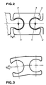
- la fig. 2 est une coupe horizontale de l'élément de liaison représenté à la figure 1, et
- la fig. 3 est une coupe horizontale d'une variante d'exécution de l'élément de liaison.
- Comme représenté à la figure 1, l'ensemble de balisage comprend des éléments principaux 1 et des éléments de liaison 2 destinés à solidariser les éléments principaux entre eux et à assurer la continuité de la forme de l'ensemble. Les éléments principaux et des éléments de liaison sont creux.
- Les éléments principaux sont de forme allongée. Ils comportent une partie inférieure de base transversalement plus large que leur partie supérieure et une partie médiane dont la largeur varie entre celle de la partie inférieure et celle de la partie supérieure. Ils sont limités à chacune de leurs extrémités longitudinales par des faces planes verticales 16, 16′, chacune desdites faces comportant un élément d'accrochage en saillie 3, 3′ de forme générale cylindrique, disposé verticalement et respectivement solidaire de chacune des faces d'extrémité 16, 16′ par l'intermédiaire de parties de liaison 17, 17′. Un pont inférieur 12, destiné à l'écoulement transversal des eaux de ruissellement, est situé dans la partie inférieure de l'élément. Ce pont, qui est de préférence situé dans la partie médiane de l'élément, constitue par ses parois latérales 13 et sa paroi supérieure un raidisseur transversal de l'élément principal.
- La face supérieure des éléments principaux comporte une rainure longitudinale 15 sur toute la longueur de l'élément. Une ouverture 14 est également prévue dans la partie supérieure de l'élément. Cette ouverture qui peut être munie d'un dispositif de fermeture est destinée au lestage des éléments, par exemple avec de l'eau, du sable, ou tout autre produit lestant.
- Les éléments de liaison 2 sont de hauteur inférieure à celle des éléments principaux. Ils comportent deux parties alvéolaires 4, 4′ de forme générale cylindrique et situées de part et d'autre de l'élément sur toute la hauteur de l'élément. Ces parties alvéolaires débouchent également sur les faces latérales de l'élément de liaison par une ouverture verticale constituée entre des rebords 5, 5′ des parties alvéolaires de façon à constituer une fente de largeur sensiblement supérieure à l'épaisseur latérale des parties de liaison 17, 17′ reliant les parties d'accrochage 3, 3′ à l'élément principal 1.
- La solidarisation de deux éléments principaux voisins est réalisée par l'introduction par coulissement vertical d'un élément de liaison entre deux éléments principaux, les parties alvéolaires 4, 4′ des éléments de liaison coulissant respectivement autour des éléments d'accrochage 3, 3′ des deux éléments principaux voisins.
- Des organes de retenue faisant partie intégrante des éléments principaux, disposés par exemple sur la partie inférieure des faces d'extrémités 16, 16′ des éléments principaux ou sur la partie inférieure des éléments d'accrochage 3, 3′ permettent de maintenir les éléments de liaison à une certaine distance du sol lorsqu'ils ont été mis en place, de façon à permettre le passage des eaux de ruissellement. Selon une variante, les organes de retenue sont disposés sur les éléments de liaison, par exemple à leur surface inférieure ou à leur surface supérieure.
- La présence des éléments de liaison décrits ci-dessus permet de réaliser la solidarisation de l'ensemble et le blocage des éléments principaux entre eux, grâce à la conformation des parties de bord 5, 5′ des éléments de liaison, qui empêchent tout déplacement latéral relatif des éléments principaux.
- Afin d'augmenter la résistance de l'ensemble et d'empêcher toute désolidarisation de l'ensemble en cas de choc, même violent, deux types d'organes de blocage complémentaires sont prévus, qui peuvent être utilisés conjointement ou séparément. Il s'agit d'une part de broches 6 à double tige 7, 7′, en matière plastique, en métal ou en toute autre matière résistante, les tiges 7, 7′ étant destinées à être introduites dans des tous 11, 11′ prévus dans la partie centrale des parties d'accrochage 3, 3′ des éléments principaux. D'autre part, des tiges ou câbles peuvent être disposés dans la rainure 15 des éléments principaux, leur longueur pouvant être un multiple de la somme des longueurs d'un élément principal et d'un élément de liaison. Ces tiges ou câbles sont munis d'organes d'accrochage à leurs extrémités, comme par exemple respectivement une tige recourbée 9 et un oeillet 10. Ces organes peuvent être en métal, en matière plastique ou en toute autre matière résistante.
- Comme représenté à la figure 2, les parties latérales des éléments de liaison comportent un angle de dépouille et des bords arrondis leur permettant un ajustement angulaire 18 autour des éléments d'accrochage 3, 3′ des éléments principaux. Cet ajustement angulaire permet la réalisation de balisage en courbe et notamment la réalisation de ronds-points pouvant avoir par exemple des diamètres de l'ordre de 6 mètres. Bien entendu, ces caractéristiques ne sont nullement limitatives, la forme des éléments pouvant être adaptée selon les circonstances, notamment pour la réalisation d'îlots.
- Comme les éléments principaux, les éléments de liaison peuvent être agencés de façon à être lestés. Une ouverture doit dans ce cas être prévue, de préférence dans la partie supérieure de l'élément. Cette ouverture peut être munie d'un dispositif de fermeture.
- Selon une variante, représentée à la figure 3, les éléments de liaison comportent deux parties longitudinalement inclinées d'un angle 19 l'une par rapport à l'autre, de façon à permettre la réalisation de courbes ou îlots de plus petits rayons.
- Les éléments principaux et/ou les éléments de liaison peuvent être pourvus de patins anti-glissement, destinés à augmenter leur adhérence au sol.
- Les éléments principaux et les éléments de liaison peuvent être réalisés, par exemple, en polyéthylène, en PVC, ou toute matière plastique rotomoulée ou injectée, en un mélange de fibres de verre et de résine, en aluminium ou en toute autre matière. Dans une version d'exécution réalisée en matière plastique, la longueur unitaire des éléments principaux est de 1 mètre, l'épaisseur des parois étant de 7 millimètres et le poids d'un élément étant de 10 kilos. Bien entendu, toutes autres dimensions peuvent être réalisées, selon les capacités des fabricants et l'emploi auquel est destiné l'ensemble de balisage.
- Dans une version simplifiée de l'ensemble, les éléments principaux et les éléments de liaison ne peuvent pas être lestés. Ils ne comportent donc pas d'ouverture à cet effet. De même, la rainure longitudinale 15 sur les éléments principaux peut ne pas exister.
- Les éléments de l'ensemble peuvent être réalisés ou peints en plusieurs couleurs. Les éléments principaux peuvent par exemple être de couleur rouge et les éléments de liaison de couleur blanche. On peut aussi prévoir, par exemple, d'alterner la couleur des éléments principaux. Les éléments de l'ensemble peuvent être équipés de bandes réfléchissantes ou autres produits similaires destinés à la sécurité de nuit.
- Selon un autre mode d'exécution de l'ensemble, non représenté, les éléments d'accrochage 3, 3′ des éléments principaux et les parties alvéolaires 4, 4′ des éléments de liaison peuvent être disposés horizontalement, la mise en place des éléments de liaison s'effectuant latéralement.
Claims (10)
Priority Applications (5)
| Application Number | Priority Date | Filing Date | Title |
|---|---|---|---|
| AT87810501T ATE72465T1 (de) | 1987-09-01 | 1987-09-01 | Bausatz zur begrenzungskennzeichnung. |
| FR878712138A FR2619841B1 (fr) | 1987-09-01 | 1987-09-01 | Ensemble de balisage |
| EP87810501A EP0305624B1 (fr) | 1987-09-01 | 1987-09-01 | Ensemble de balisage |
| CH3351/87A CH672158A5 (fr) | 1987-09-01 | 1987-09-01 | |
| DE8787810501T DE3776659D1 (de) | 1987-09-01 | 1987-09-01 | Bausatz zur begrenzungskennzeichnung. |
Applications Claiming Priority (1)
| Application Number | Priority Date | Filing Date | Title |
|---|---|---|---|
| EP87810501A EP0305624B1 (fr) | 1987-09-01 | 1987-09-01 | Ensemble de balisage |
Publications (2)
| Publication Number | Publication Date |
|---|---|
| EP0305624A1 true EP0305624A1 (fr) | 1989-03-08 |
| EP0305624B1 EP0305624B1 (fr) | 1992-02-05 |
Family
ID=8198415
Family Applications (1)
| Application Number | Title | Priority Date | Filing Date |
|---|---|---|---|
| EP87810501A Expired - Lifetime EP0305624B1 (fr) | 1987-09-01 | 1987-09-01 | Ensemble de balisage |
Country Status (5)
| Country | Link |
|---|---|
| EP (1) | EP0305624B1 (fr) |
| AT (1) | ATE72465T1 (fr) |
| CH (1) | CH672158A5 (fr) |
| DE (1) | DE3776659D1 (fr) |
| FR (1) | FR2619841B1 (fr) |
Cited By (12)
| Publication number | Priority date | Publication date | Assignee | Title |
|---|---|---|---|---|
| WO1990010753A1 (fr) * | 1989-03-07 | 1990-09-20 | Philip Richard Mead | Unites de gestion de trafic |
| EP0407277A2 (fr) * | 1989-07-06 | 1991-01-09 | Materiels Et Applications De Securite Pour Les Aeroports, L'industrie Et Les Routes (Masair) | Elément séparateur de voies destiné à être assemblé à d'autres éléments pour former un séparateur de voies |
| EP0442249A1 (fr) * | 1990-02-16 | 1991-08-21 | Sinterplast S.R.L. | Dispositif d'absorption d'impacts pour garde-rails |
| GB2248867A (en) * | 1990-10-18 | 1992-04-22 | Rose Enterprises Inc | Highway barrier |
| FR2676762A1 (fr) * | 1991-05-22 | 1992-11-27 | Sodirel Sa | Systeme modulaire de balisage et de separation de voies autoroutieres. |
| WO1993012300A1 (fr) * | 1991-12-10 | 1993-06-24 | 'societe Commerciale Filtray's' | Separateur de trafic et systeme de separation de trafic constitue de tels separateurs |
| DE9310254U1 (de) * | 1993-07-09 | 1994-08-25 | Maibach Verkehrssicherheit | Leitschwelle |
| WO1999053145A1 (fr) * | 1998-04-10 | 1999-10-21 | Galiana Raphael | Separateur et barriere de protection ou de delimitation, par exemple pour voie de circulation automobile |
| EP1380696A1 (fr) * | 2002-07-11 | 2004-01-14 | Colas | Dispositif de retenue modulaire et procédé de pose d'un tel dispositif |
| US9856674B1 (en) * | 2017-06-01 | 2018-01-02 | Tawny Pond | Temporary fence assembly |
| GB2555529A (en) * | 2016-09-12 | 2018-05-02 | Rosehill Polymers Group Ltd | Barrier |
| US20210071375A1 (en) * | 2017-12-12 | 2021-03-11 | Emanuele SALVADOR | Kinetic energy absorbing barrier structure |
Citations (17)
| Publication number | Priority date | Publication date | Assignee | Title |
|---|---|---|---|---|
| FR1395746A (fr) * | 1964-03-04 | 1965-04-16 | Glissière de sécurité | |
| FR1472186A (fr) * | 1966-01-18 | 1967-03-10 | B L A Sa De Beon Luyrieu Ain S | Barrière-glissière de sécurité |
| US3326099A (en) * | 1964-02-18 | 1967-06-20 | Autostrade Concess Const | Safety barrier for roadways |
| FR1600956A (fr) * | 1967-12-06 | 1970-08-03 | ||
| GB1327687A (en) * | 1971-08-14 | 1973-08-22 | Mead P R | Building block |
| US3958890A (en) * | 1975-08-11 | 1976-05-25 | Victor Ferrari | Apparatus and method for moving roadway lane dividers |
| FR2294269A1 (fr) * | 1974-12-13 | 1976-07-09 | Peter Bofinger | Verrou de jonction de garde-fou prefabrique de beton |
| US4059362A (en) * | 1976-11-24 | 1977-11-22 | Smith Rodney I | Concrete highway traffic barricade having integrally formed coupling |
| EP0065199A2 (fr) * | 1981-05-09 | 1982-11-24 | Reinhard Juraschek | Système d'accouplement pour la réalisation de structures limitatives et bloc interassemblable pour ce système |
| DE3123342A1 (de) * | 1981-06-12 | 1983-01-05 | Karl 7137 Sternenfels Stäbler | "bausatz zur erstellung von flaechigen oder raeumlichen gebilden mit waenden, die aus miteinander verbindbaren teilen zusammensetzbar sind" |
| EP0125817A1 (fr) * | 1983-04-18 | 1984-11-21 | Quick-Steel Engineering Pty Limited | Délimitation déplaçable pour voie de circulation |
| AU554614B2 (en) * | 1982-03-23 | 1986-08-28 | Pedro Solorzano Cortes | Road barrier |
| FR2584112A1 (fr) * | 1985-07-01 | 1987-01-02 | France Autoroutes Sud | Dispositif de securite pour bordure de voie de circulation |
| FR2585047A1 (fr) * | 1985-07-22 | 1987-01-23 | Tech Special Securite | Dispositif de securite pour routes, autoroutes et voies urbaines, pour separer deux files de circulation |
| US4653954A (en) * | 1985-12-09 | 1987-03-31 | Booth William L | Apparatus for moving a traffic barrier |
| DE8706087U1 (fr) * | 1986-05-07 | 1987-07-09 | Rausch, Peter, Ing., Thoerl, Steiermark, At | |
| US4681302A (en) * | 1983-12-02 | 1987-07-21 | Thompson Marion L | Energy absorbing barrier |
-
1987
- 1987-09-01 AT AT87810501T patent/ATE72465T1/de not_active IP Right Cessation
- 1987-09-01 CH CH3351/87A patent/CH672158A5/fr not_active IP Right Cessation
- 1987-09-01 DE DE8787810501T patent/DE3776659D1/de not_active Expired - Fee Related
- 1987-09-01 FR FR878712138A patent/FR2619841B1/fr not_active Expired
- 1987-09-01 EP EP87810501A patent/EP0305624B1/fr not_active Expired - Lifetime
Patent Citations (18)
| Publication number | Priority date | Publication date | Assignee | Title |
|---|---|---|---|---|
| US3326099A (en) * | 1964-02-18 | 1967-06-20 | Autostrade Concess Const | Safety barrier for roadways |
| FR1395746A (fr) * | 1964-03-04 | 1965-04-16 | Glissière de sécurité | |
| FR1472186A (fr) * | 1966-01-18 | 1967-03-10 | B L A Sa De Beon Luyrieu Ain S | Barrière-glissière de sécurité |
| FR91688E (fr) * | 1966-01-18 | 1968-07-26 | B L A Sa De Beon Luyrieu Ain S | |
| FR1600956A (fr) * | 1967-12-06 | 1970-08-03 | ||
| GB1327687A (en) * | 1971-08-14 | 1973-08-22 | Mead P R | Building block |
| FR2294269A1 (fr) * | 1974-12-13 | 1976-07-09 | Peter Bofinger | Verrou de jonction de garde-fou prefabrique de beton |
| US3958890A (en) * | 1975-08-11 | 1976-05-25 | Victor Ferrari | Apparatus and method for moving roadway lane dividers |
| US4059362A (en) * | 1976-11-24 | 1977-11-22 | Smith Rodney I | Concrete highway traffic barricade having integrally formed coupling |
| EP0065199A2 (fr) * | 1981-05-09 | 1982-11-24 | Reinhard Juraschek | Système d'accouplement pour la réalisation de structures limitatives et bloc interassemblable pour ce système |
| DE3123342A1 (de) * | 1981-06-12 | 1983-01-05 | Karl 7137 Sternenfels Stäbler | "bausatz zur erstellung von flaechigen oder raeumlichen gebilden mit waenden, die aus miteinander verbindbaren teilen zusammensetzbar sind" |
| AU554614B2 (en) * | 1982-03-23 | 1986-08-28 | Pedro Solorzano Cortes | Road barrier |
| EP0125817A1 (fr) * | 1983-04-18 | 1984-11-21 | Quick-Steel Engineering Pty Limited | Délimitation déplaçable pour voie de circulation |
| US4681302A (en) * | 1983-12-02 | 1987-07-21 | Thompson Marion L | Energy absorbing barrier |
| FR2584112A1 (fr) * | 1985-07-01 | 1987-01-02 | France Autoroutes Sud | Dispositif de securite pour bordure de voie de circulation |
| FR2585047A1 (fr) * | 1985-07-22 | 1987-01-23 | Tech Special Securite | Dispositif de securite pour routes, autoroutes et voies urbaines, pour separer deux files de circulation |
| US4653954A (en) * | 1985-12-09 | 1987-03-31 | Booth William L | Apparatus for moving a traffic barrier |
| DE8706087U1 (fr) * | 1986-05-07 | 1987-07-09 | Rausch, Peter, Ing., Thoerl, Steiermark, At |
Cited By (17)
| Publication number | Priority date | Publication date | Assignee | Title |
|---|---|---|---|---|
| WO1990010753A1 (fr) * | 1989-03-07 | 1990-09-20 | Philip Richard Mead | Unites de gestion de trafic |
| EP0407277A2 (fr) * | 1989-07-06 | 1991-01-09 | Materiels Et Applications De Securite Pour Les Aeroports, L'industrie Et Les Routes (Masair) | Elément séparateur de voies destiné à être assemblé à d'autres éléments pour former un séparateur de voies |
| EP0407277A3 (en) * | 1989-07-06 | 1992-03-18 | Materiels Et Applications De Securite Pour Les Aeroports, L'industrie Et Les Routes (Masair) | Interconnectable elements for assembling a lane-separation barrier |
| EP0442249A1 (fr) * | 1990-02-16 | 1991-08-21 | Sinterplast S.R.L. | Dispositif d'absorption d'impacts pour garde-rails |
| GB2248867B (en) * | 1990-10-18 | 1994-09-21 | Rose Enterprises Inc | Stand alone highway barrier |
| GB2248867A (en) * | 1990-10-18 | 1992-04-22 | Rose Enterprises Inc | Highway barrier |
| FR2676762A1 (fr) * | 1991-05-22 | 1992-11-27 | Sodirel Sa | Systeme modulaire de balisage et de separation de voies autoroutieres. |
| WO1993012300A1 (fr) * | 1991-12-10 | 1993-06-24 | 'societe Commerciale Filtray's' | Separateur de trafic et systeme de separation de trafic constitue de tels separateurs |
| DE9310254U1 (de) * | 1993-07-09 | 1994-08-25 | Maibach Verkehrssicherheit | Leitschwelle |
| WO1999053145A1 (fr) * | 1998-04-10 | 1999-10-21 | Galiana Raphael | Separateur et barriere de protection ou de delimitation, par exemple pour voie de circulation automobile |
| US6439801B1 (en) | 1998-04-10 | 2002-08-27 | Raphael Galiana | Protective or delimiting barrier having a flexible connecting system |
| EP1380696A1 (fr) * | 2002-07-11 | 2004-01-14 | Colas | Dispositif de retenue modulaire et procédé de pose d'un tel dispositif |
| FR2842224A1 (fr) * | 2002-07-11 | 2004-01-16 | Colas Sa | Dispositif de retenue modulaire et procede de pose d'un tel dispositif |
| GB2555529A (en) * | 2016-09-12 | 2018-05-02 | Rosehill Polymers Group Ltd | Barrier |
| GB2555529B (en) * | 2016-09-12 | 2020-02-26 | Rosehill Polymers Group Ltd | Barrier |
| US9856674B1 (en) * | 2017-06-01 | 2018-01-02 | Tawny Pond | Temporary fence assembly |
| US20210071375A1 (en) * | 2017-12-12 | 2021-03-11 | Emanuele SALVADOR | Kinetic energy absorbing barrier structure |
Also Published As
| Publication number | Publication date |
|---|---|
| CH672158A5 (fr) | 1989-10-31 |
| DE3776659D1 (de) | 1992-03-19 |
| FR2619841B1 (fr) | 1989-12-22 |
| FR2619841A1 (fr) | 1989-03-03 |
| ATE72465T1 (de) | 1992-02-15 |
| EP0305624B1 (fr) | 1992-02-05 |
Similar Documents
| Publication | Publication Date | Title |
|---|---|---|
| EP0305624B1 (fr) | Ensemble de balisage | |
| EP0479661B1 (fr) | Curseur pour sachets ou sacs munis d'une fermeture plastique à deux profils emboitables | |
| FR2777304A1 (fr) | Separateur et barriere de protection ou de delimitation, par exemple pour voie de circulation automobile | |
| FR2485897A1 (fr) | Mallette | |
| WO1993012300A1 (fr) | Separateur de trafic et systeme de separation de trafic constitue de tels separateurs | |
| EP0465748A1 (fr) | Elément de balisage et ensemble de balisage formé par de tels éléments | |
| BE1000869A6 (fr) | Ensemble de balisage. | |
| EP0307291A1 (fr) | Tête de pont pour le passage transversal d'un fossé | |
| FR2813624A1 (fr) | Profile de raccord et d'etancheite, dispositif de raccord, panneau a structure sandwich, et ensemble de facade, de cloison ou de couverture | |
| EP0980333B1 (fr) | Dispositif de suspension de sachet | |
| EP1022833B1 (fr) | Adaptateur pour support de mécanisme, et support de mécanisme équipé d'au moins un tel adaptateur, notamment pour appareillage électrique | |
| EP0670947A1 (fr) | Passerelle pour le franchissement d'obstacles. | |
| EP0641964B1 (fr) | Dispositif de support de câble ou conduits | |
| EP0406063B1 (fr) | Pavé en matière synthétique et bordure d'accotement constituée par de tels pavés | |
| EP2902555B1 (fr) | Piece de raccordement sur une ligne de drainage d'eaux pluviales, galerie de visite pour lignes de drainage d'eaux pluviales et ensemble de drainage comprenant ladite galerie de visite | |
| FR2670518A1 (fr) | Bloc separateur pour voies de circulation. | |
| EP1196660A1 (fr) | Dispositif de securite routiere, pieces constitutives et leur procede de fabrication | |
| EP1010843B1 (fr) | Dispositif formant pied pour piquet ou mât, notamment pour pied de tonelle ou panneau, et son procédé de fermeture | |
| FR2704823A1 (fr) | Chenille pour véhicule présentant des protubérances allongées. | |
| EP1054115A1 (fr) | Bloc de construction destiné à la réalisation d'un angle de mur de bâtiment. | |
| FR2750147A1 (fr) | Barriere modulable en thermodurcissable et thermoplastique | |
| FR2676762A1 (fr) | Systeme modulaire de balisage et de separation de voies autoroutieres. | |
| FR2703090A1 (fr) | Joint d'extrémité de panneau de paroi moulée. | |
| FR2688242A1 (fr) | Dispositif de signalisation routiere equipant notamment les murs de securite separateurs de voies. | |
| FR2793399A1 (fr) | Verseur plat pouvant etre jetable |
Legal Events
| Date | Code | Title | Description |
|---|---|---|---|
| PUAI | Public reference made under article 153(3) epc to a published international application that has entered the european phase |
Free format text: ORIGINAL CODE: 0009012 |
|
| AK | Designated contracting states |
Kind code of ref document: A1 Designated state(s): AT BE CH DE ES FR GB GR IT LI LU NL SE |
|
| 17P | Request for examination filed |
Effective date: 19890613 |
|
| 17Q | First examination report despatched |
Effective date: 19900305 |
|
| GRAA | (expected) grant |
Free format text: ORIGINAL CODE: 0009210 |
|
| AK | Designated contracting states |
Kind code of ref document: B1 Designated state(s): AT BE CH DE ES FR GB GR IT LI LU NL SE |
|
| PG25 | Lapsed in a contracting state [announced via postgrant information from national office to epo] |
Ref country code: GR Free format text: LAPSE BECAUSE OF FAILURE TO SUBMIT A TRANSLATION OF THE DESCRIPTION OR TO PAY THE FEE WITHIN THE PRESCRIBED TIME-LIMIT Effective date: 19920205 Ref country code: AT Effective date: 19920205 Ref country code: IT Free format text: LAPSE BECAUSE OF FAILURE TO SUBMIT A TRANSLATION OF THE DESCRIPTION OR TO PAY THE FEE WITHIN THE PRE;WARNING: LAPSES OF ITALIAN PATENTS WITH EFFECTIVE DATE BEFORE 2007 MAY HAVE OCCURRED AT ANY TIME BEFORE 2007. THE CORRECT EFFECTIVE DATE MAY BE DIFFERENT FROM THE ONE RECORDED.SCRIBED TIME-LIMIT Effective date: 19920205 Ref country code: NL Effective date: 19920205 Ref country code: GB Effective date: 19920205 Ref country code: SE Effective date: 19920205 |
|
| REF | Corresponds to: |
Ref document number: 72465 Country of ref document: AT Date of ref document: 19920215 Kind code of ref document: T |
|
| REF | Corresponds to: |
Ref document number: 3776659 Country of ref document: DE Date of ref document: 19920319 |
|
| PG25 | Lapsed in a contracting state [announced via postgrant information from national office to epo] |
Ref country code: ES Free format text: LAPSE BECAUSE OF FAILURE TO SUBMIT A TRANSLATION OF THE DESCRIPTION OR TO PAY THE FEE WITHIN THE PRESCRIBED TIME-LIMIT Effective date: 19920516 |
|
| NLV1 | Nl: lapsed or annulled due to failure to fulfill the requirements of art. 29p and 29m of the patents act | ||
| GBV | Gb: ep patent (uk) treated as always having been void in accordance with gb section 77(7)/1977 [no translation filed] | ||
| PG25 | Lapsed in a contracting state [announced via postgrant information from national office to epo] |
Ref country code: LU Free format text: LAPSE BECAUSE OF NON-PAYMENT OF DUE FEES Effective date: 19920930 Ref country code: BE Effective date: 19920930 |
|
| PLBE | No opposition filed within time limit |
Free format text: ORIGINAL CODE: 0009261 |
|
| STAA | Information on the status of an ep patent application or granted ep patent |
Free format text: STATUS: NO OPPOSITION FILED WITHIN TIME LIMIT |
|
| 26N | No opposition filed | ||
| BERE | Be: lapsed |
Owner name: BOSTRA TRADERS INC. Effective date: 19920930 |
|
| PGFP | Annual fee paid to national office [announced via postgrant information from national office to epo] |
Ref country code: DE Payment date: 19930705 Year of fee payment: 7 |
|
| PGFP | Annual fee paid to national office [announced via postgrant information from national office to epo] |
Ref country code: CH Payment date: 19930722 Year of fee payment: 7 |
|
| PGFP | Annual fee paid to national office [announced via postgrant information from national office to epo] |
Ref country code: FR Payment date: 19930730 Year of fee payment: 7 |
|
| PG25 | Lapsed in a contracting state [announced via postgrant information from national office to epo] |
Ref country code: LI Effective date: 19940930 Ref country code: CH Effective date: 19940930 |
|
| PG25 | Lapsed in a contracting state [announced via postgrant information from national office to epo] |
Ref country code: FR Effective date: 19950531 |
|
| REG | Reference to a national code |
Ref country code: CH Ref legal event code: PL |
|
| PG25 | Lapsed in a contracting state [announced via postgrant information from national office to epo] |
Ref country code: DE Effective date: 19950601 |
|
| REG | Reference to a national code |
Ref country code: FR Ref legal event code: ST |