EP0125817A1 - Délimitation déplaçable pour voie de circulation - Google Patents
Délimitation déplaçable pour voie de circulation Download PDFInfo
- Publication number
- EP0125817A1 EP0125817A1 EP84302690A EP84302690A EP0125817A1 EP 0125817 A1 EP0125817 A1 EP 0125817A1 EP 84302690 A EP84302690 A EP 84302690A EP 84302690 A EP84302690 A EP 84302690A EP 0125817 A1 EP0125817 A1 EP 0125817A1
- Authority
- EP
- European Patent Office
- Prior art keywords
- modules
- divider
- lane
- roadway
- lane divider
- Prior art date
- Legal status (The legal status is an assumption and is not a legal conclusion. Google has not performed a legal analysis and makes no representation as to the accuracy of the status listed.)
- Granted
Links
- 230000004888 barrier function Effects 0.000 claims description 36
- 238000000034 method Methods 0.000 claims description 11
- 230000000452 restraining effect Effects 0.000 claims description 3
- 239000011150 reinforced concrete Substances 0.000 claims description 2
- 238000000151 deposition Methods 0.000 claims 1
- 239000004567 concrete Substances 0.000 description 5
- 239000002184 metal Substances 0.000 description 5
- 239000000463 material Substances 0.000 description 4
- 229910000831 Steel Inorganic materials 0.000 description 3
- 230000004048 modification Effects 0.000 description 3
- 238000012986 modification Methods 0.000 description 3
- 229920002635 polyurethane Polymers 0.000 description 3
- 239000004814 polyurethane Substances 0.000 description 3
- 239000010959 steel Substances 0.000 description 3
- 238000010276 construction Methods 0.000 description 2
- 229920003023 plastic Polymers 0.000 description 2
- 239000004033 plastic Substances 0.000 description 2
- 229910001294 Reinforcing steel Inorganic materials 0.000 description 1
- 230000000295 complement effect Effects 0.000 description 1
- 230000003014 reinforcing effect Effects 0.000 description 1
- 239000007787 solid Substances 0.000 description 1
Images


Classifications
-
- E—FIXED CONSTRUCTIONS
- E01—CONSTRUCTION OF ROADS, RAILWAYS, OR BRIDGES
- E01F—ADDITIONAL WORK, SUCH AS EQUIPPING ROADS OR THE CONSTRUCTION OF PLATFORMS, HELICOPTER LANDING STAGES, SIGNS, SNOW FENCES, OR THE LIKE
- E01F15/00—Safety arrangements for slowing, redirecting or stopping errant vehicles, e.g. guard posts or bollards; Arrangements for reducing damage to roadside structures due to vehicular impact
- E01F15/006—Lane control by movable lane separating barriers, e.g. shiftable barriers, retractable kerbs ; Apparatus or barriers specially adapted therefor, e.g. wheeled barriers
-
- E—FIXED CONSTRUCTIONS
- E01—CONSTRUCTION OF ROADS, RAILWAYS, OR BRIDGES
- E01F—ADDITIONAL WORK, SUCH AS EQUIPPING ROADS OR THE CONSTRUCTION OF PLATFORMS, HELICOPTER LANDING STAGES, SIGNS, SNOW FENCES, OR THE LIKE
- E01F9/00—Arrangement of road signs or traffic signals; Arrangements for enforcing caution
- E01F9/50—Road surface markings; Kerbs or road edgings, specially adapted for alerting road users
- E01F9/576—Traffic lines
- E01F9/594—Traffic lines movable for reuse at different locations
Definitions
- the present invention relates to a system of transferable roadway lane dividers and a method of transferring said dividers. Such a system is necessary due to the flapping of roadway dividers on bridges and major roads during peak hours.
- channels are made in the road transverse to the traffic flow and hydraulically operated carriages are located within said channels-for movement along said channels.
- the elongated barrier is affixed to posts which are connected to said carriages such that upon movement of the carriages within the channels the barrier is transferred to its new positon.
- This system suffers from several disadvantages such as that the roadway must be dug up to permit the embedding of the channels and the necessary hydraulic systems, the barriers by their nature do not provide adequate protection for impact by vehicles colliding with the barrier, and the channels are prone to fill with debris which could interfere with the efficient operation of the system.
- a system is shown in Ferrari U.S. Patent 3,958,890 which does not involve cutting into the roadway surface, but utilizes gantries extending over the roadway along each gantry runs a trolley hoist connected to the barrier.
- the trolley hoists selectively raise and move the barrier in conjunction with other trolley hoists to the desired positions.
- This system while not involving any cutting into the roadway surface does have the disadvantages of the cost of the gantries and hoists; the maintanence of the system and susceptibility of the hoists to weather conditions.
- the present invention provides an improved and efficient transferable roadway lane divider comprising a transferable roadway lane divider comprising divider modules (1, 29) connected together such that adjacent modules can pivot with respect to each other to form an elongated divider for separating traffic lanes, each of said divider modules having a bottom surface (5) which is adapted to rest directly on the roadway surface characterised in that there is provided transfer means (6) above the section's bottom surface for enabling said modules to be pulled upwardly by substantially S-shaped elongated transfer device (8) and slid along said transfer device as said transfer device traverses the roadway to cause said divider to be moved from a first roadway position to a second roadway position, said transfer means comprises at least one channel (6, 27, 34) extending substantially horizontally through each said modules and into which a corresponding slide means (8, 24) of said transfer device is adapted to fit.
- a moveable lane divider system characterised in that every second module (29) has a locking member (51) which is of slightly less than twice the length of a divider module (29), and which has two slotted projections (63) which fit within the recesses (58) and are slideably held therein by means of rods (65) projection through the slots (64).
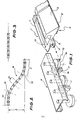
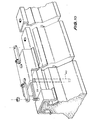
- Each lane divider is made up of individual sections 1 which are hingedly joined together on a pair of links 2. The required number of sections 1 are joined together to form any suitable length of divider with each end containing a shaped section having only one hinge attachment and a substantially bullet shaped other end.
- the divider sections 1 can be shaped as shown in figure 1 in which each section has two chamfered edges 3 to provide a smooth surface in case a motorist's tyre accidentally runs onto the divider. It is desirable that the height of the divider be relatively short while using a wide base 4 to provide a solid large surface area of contact with the roadway, so as to resist lateral movement of the divider if accidentally bumped by a vehicle.
- the sections of the lane divider can be made of any suitable material such as concrete or plastics or sheet metal.
- each section has in inverted T-shaped cross-section channel 6 running longitudinal along the upper face 7.
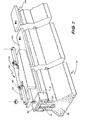
- a transfer mechanism as shown in figure 4 can be used. This consists of a roller conveyor 8 comprising a series of rollers as shown in figure 1.
- the transfer mechanism is s-shaped as shown schematically in figure 2 with its total width 9 corresponding with the distance between traffic lanes. It can preferably be mounted, as shown schematically in figure 4, from below a trailer.
- the front section 10 and the rear . section 11 are preferably hinged at pivots 12 and 13 such that they can hinge back to the body of the trailer to keep within the allowable width for travel on the road.
- the straight centre section 14 can be telescoped in and out to achieve variable lane widths.
- roller conveyor To move the lane divider from one side of the lane to the other, one simply drives a vehicle with the transfer mechanism mounted beneath or towed behind on a trailer, and engages the leading rollers 15 within the T-shaped channel 6. As the transfer mechanism is moved along the lane the lane dividers are threaded along the roller conveyor 8 and are deposited by the rear section 11 on the other side of the lane.
- roller conveyor Three types of rollers are used the roller conveyor to facilitate the movement of the sections along the rollers. These are the guide rollers 16 which engage within the cross arm of the T-shaped channel, lift rollers 17 which lift the sections off the road and engage with the surfaces 19 and restraining rollers 18 which stabilize the transfer.
- the vehicle or trailer carries the channel underneath the wheels with the mouth extending on one side of the vehicle with the outlet extending on the other side of the vehicle such that the vehicle can drive the centre of the lane to reposition the lane divider.
- the channel may be positioned in other relationships with respect to the vehicle.
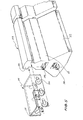
- Figure 3 shows an aligning mechanism useable to straighten out the lane divider in cases where the lane divider is accidentally knocked out of position by a vehicle or other circumstances.
- each section has two sloping sides 22 to provide a smooth surface in case a motorist's tyre accidentally runs onto the divider.
- a centre section 21 extends upwardly from the sides 22 to provide a substantial barrier which is readily visible.
- the divider section is 800 mm in height by 600 mm in width and approximately 1 metre in length.
- the sections of the lane divider can be made of any suitable material such as concrete or plastics or sheet metal.
- the sections are constructed of reinforced concrete with the respective hinges 20 on opposite ends of a section being formed on the one bar of metal, with the reinforcing rods positioned to give suitable strength.
- each section has a T-shaped projection extending from the centre section 21 and running longitudinally along the divider.
- a transfer mechanism similar to that as shown in figure 4 can be used.
- This modified transfer mechanism comprises a roller conveyer 24 comprising a series of rollers 26 angularly attached to the channel 25 as shown in figures 5 and 6. Each roller is positioned so as to engage with a radius at the neck of the T as shown in figure 6.
- a means of releasably locking the transferable lane barrier modules is required to provide stability against lateral shift due to impact by vehicles.
- an elongated locking member in the shape of an inverted channel which fits over said projection with a small clearance can be used.
- the elongated locking member is hingedly connected to the adjacent locking member and with the locking members staggered the lane divider modules are locked together.
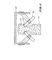
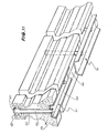
- the moveable lane divider barrier modules 29 are of similar shape to those described with reference to figures 5 and 6. However these modules have a top which is formed of heavy steel plate rather than of concrete.
- the top 30 has projections 31 extending from along its length, set into the concrete 32 of the module, to ensure adequate bonding of the top 30 to the module 29.
- the top 30 and the neck 33 of the module 29 form transfer grooves 34 into which can be engaged transfer rollers or other suitable transfer devices in a similar method to that described with respect to figures 5 and 6.
- elongated locking members 35 in the form of an inverted channel 36 are used. These are pivotally connected together for example, as shown in figure 7 by means of an elongated member 37 pivotally connected to bolts 38 by nuts on adjacent locking members 35.
- the locking members 35 are of approximately the same length as the modules 29 and are so shaped that the top 30 fits with a small clearance into the channel 36 such that when the locking members 35 are positioned so as to bridge across adjacent modules 29, the modules are secured against lateral pivotal movement relative to each other.
- each locking member 35 is vertically slideably attached to adjacent modules by means of rods 39 which are slideably held in bores 40 in the modules as shown in figure 8 and in dotted lines in figure 10.
- each locking member 35 has two projecting rods which fit into respective bores on adjacent modules.
- the side members 41 of the channel 36 extend downwardly to cover the transfer grooves 34 when the locking member is in its locking position.
- FIG 8 Another embodiment of a lane divider barrier system is shown in figure 8 which is similar in construction to that shown in figure 7 except that the top 42 of the module and the transfer groove 34 are both formed from sheet metal plate 43.
- a leading locking member 15 is shown in figure 9.
- This member 44 has a tapered leading edge 45, which when the moveable barrier is to be removed, is engaged by a roller or other device which can be mounted on a similar transfer device as described previously. Therefore when the transfer device moves along the modules, a ramp (not shown) engages under the leading edge 45 of the locking member 44 and forces the locking member to be lifted clear of the top 30 of the modules, such that the bottom edge 48 of each side 46 of the channel rests on a plurality of rollers 47.
- the transfer groove 34 of the modules are then engaged by the transfer device (not shown) and the modules and locking members are transferred in a similar manner to the manner to that described previously.
- the locking members are lowered into locking engagement onto the top of the modules and positioning rollers can be used to positively position the channels into locking engagement.
- the channel can have tapered or flared sides as shown in figure 10.
- the sides 46 of the channel extend down past the transfer groove 34 and fit onto a shoulder 49.
- the module 29 has the surface of the concrete above the shoulder 49 clad in steel to protect the top and transfer groove.
- the bores 40 are fitted with a polyurethane bush 50.
- the modules can be in the form shown in figure 11 wherein the locking members 51 are located in a longitudinal groove 52 located underneath the modules.
- the locking members as shown in figure 11 are in the form of a channel 53 which is of outer complementary shape to the recess 52.
- the locking membrs have projecting rods 54 slideably located in bores 55 in the modules and are positioned to bridge across two modules.
- the rods 54 terminate in recesses 56 located in the upper surface of the modules, and have a retaining means, such as the discs 57, located at or adjacent the free end of the rods, to prevent the rods 54 from falling out of the bores 55, when the modules are lifted.
- the recesses 56 are capped to prevent the ingress of matter into the recess.
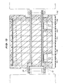
- FIG. 12 A modification of the embodiment of Figure 11 is shown in Figures 12 and 13 wherein the locking member 51 is slightly less in length than twice the length of a module 29. Therefore only every second module in a barrier needs to have affixed thereto a locking member. This embodiment is therefore cheaper to produce than the embodiment as shown in Figure 12 where every module must have a locking member attached thereto.
- the modules 29 holding the locking members 51 have two substantially rectangular recesses 58 cast into the base of the channel 52. Holes 59 pass through the walls of the module to meet with the recesses 58. To ensure adequate strength for the moduels, a grid of reinforcing steel rods 60 are used, as shown in Figure 13.
- the hinges 61 and 62 are formed from a unitary piece of steel which passes through the module, as shown in Figure 13.
- the locking members 51 each have two slotted projections 63 which fit within the recesses 58 and rods 65 pass through said holes 59 and through said slot 64 to hold said locking member 51 to the module 29. Therefore when said modules are lifted the locking member 51 disengages from the channel 52 and the projections 63 slide over the rods 65 which abut against the end of the slots 64.
- Polyurethane plugs 66 can be used to cap the ends of the rods 65.
- a transfer device as described previously can be used to move the lanes provided that the modules are lifted a sufficient height to allow the locking member 51 to hang free of the groove 52. Once the modules have been fed along the transfer device to their new position they are simply slid onto the ground wherein the locking members automatically engage into the recesses.
Landscapes
- Engineering & Computer Science (AREA)
- Architecture (AREA)
- Civil Engineering (AREA)
- Structural Engineering (AREA)
- Branching, Merging, And Special Transfer Between Conveyors (AREA)
- Refuge Islands, Traffic Blockers, Or Guard Fence (AREA)
Priority Applications (1)
| Application Number | Priority Date | Filing Date | Title |
|---|---|---|---|
| AT84302690T ATE26006T1 (de) | 1983-04-18 | 1984-04-18 | Versetzbare fahrspurteiler. |
Applications Claiming Priority (4)
| Application Number | Priority Date | Filing Date | Title |
|---|---|---|---|
| US06/485,622 US4500225A (en) | 1981-02-06 | 1983-04-18 | Transferable roadway lane divider |
| US485622 | 1983-04-18 | ||
| US509184 | 1983-06-29 | ||
| US06/509,184 US4498803A (en) | 1983-04-18 | 1983-06-29 | Moveable lane barrier locking system |
Publications (2)
| Publication Number | Publication Date |
|---|---|
| EP0125817A1 true EP0125817A1 (fr) | 1984-11-21 |
| EP0125817B1 EP0125817B1 (fr) | 1987-03-18 |
Family
ID=27048421
Family Applications (1)
| Application Number | Title | Priority Date | Filing Date |
|---|---|---|---|
| EP84302690A Expired EP0125817B1 (fr) | 1983-04-18 | 1984-04-18 | Délimitation déplaçable pour voie de circulation |
Country Status (5)
| Country | Link |
|---|---|
| US (1) | US4498803A (fr) |
| EP (1) | EP0125817B1 (fr) |
| AU (1) | AU576754B2 (fr) |
| CA (1) | CA1230001A (fr) |
| DE (1) | DE3462704D1 (fr) |
Cited By (18)
| Publication number | Priority date | Publication date | Assignee | Title |
|---|---|---|---|---|
| FR2585047A1 (fr) * | 1985-07-22 | 1987-01-23 | Tech Special Securite | Dispositif de securite pour routes, autoroutes et voies urbaines, pour separer deux files de circulation |
| AT384846B (de) * | 1985-08-05 | 1988-01-11 | Wieser Johann | Einrichtung zur wahlweisen begrenzung einer fahrspur |
| WO1988008057A1 (fr) * | 1987-04-09 | 1988-10-20 | John Costelloe | Barriere |
| EP0297182A1 (fr) * | 1987-07-01 | 1989-01-04 | Energy Absorption Systems, Inc. | Barrière de sécurité amortissante |
| FR2619400A1 (fr) * | 1987-08-14 | 1989-02-17 | Sodirel Diffusion Rgle Locale | Glissieres temporaires de securite et de signalisation et caissons pour la construction de celles-ci |
| FR2619841A1 (fr) * | 1987-09-01 | 1989-03-03 | Bostra Traders Inc | Ensemble de balisage |
| EP0311015A1 (fr) * | 1987-10-05 | 1989-04-12 | Sps Schutzplanken Gmbh | Dispositif formant glissière de sécurité |
| WO1989012142A1 (fr) * | 1987-06-10 | 1989-12-14 | Renate Klasen | Balisage de routes |
| EP0351572A2 (fr) * | 1988-06-21 | 1990-01-24 | Hermann Silbernagel | Séparateur de voies |
| EP0373279A1 (fr) * | 1987-09-15 | 1990-06-20 | Angel Garcia Ballesteros | Procédé de production in situ de barrières de sécurité |
| EP0414959A1 (fr) * | 1989-08-31 | 1991-03-06 | SPIG SCHUTZPLANKEN-PRODUKTIONS-GESELLSCHAFT MBH & CO.KG | File de modules séparateurs |
| FR2701046A1 (fr) * | 1993-02-02 | 1994-08-05 | Tss | Séparateur de voies déplaçable latéralement. |
| ES2063641A2 (es) * | 1992-04-30 | 1995-01-01 | Innovacions Tecnologiques S A | Modulo reversible polivalente para la construccion. |
| AU736430B2 (en) * | 1997-04-08 | 2001-07-26 | Roads And Traffic Authority Of New South Wales | Movable median strip |
| WO2007051219A1 (fr) * | 2005-11-04 | 2007-05-10 | Maba Fertigteilindustrie Gmbh | Muret de separation |
| EP1936036A1 (fr) | 2006-12-11 | 2008-06-25 | Eurovia | Balise avec structure de protection escamotable |
| FR2954367A1 (fr) * | 2009-12-22 | 2011-06-24 | Eurovia | Bloc beton transferable |
| EP2339071A1 (fr) * | 2009-12-22 | 2011-06-29 | TSS Technische Sicherheits-Systeme GmbH | Elément de liaison et élément de délimitation de voies de circulation |
Families Citing this family (33)
| Publication number | Priority date | Publication date | Assignee | Title |
|---|---|---|---|---|
| SE8103419L (sv) * | 1981-06-01 | 1982-12-02 | Almer Bengt Oennert | Anordning vid betongblock |
| US4632598A (en) * | 1985-07-15 | 1986-12-30 | Richards David B | Movable roadway barrier |
| US4653954A (en) * | 1985-12-09 | 1987-03-31 | Booth William L | Apparatus for moving a traffic barrier |
| US4955753A (en) * | 1988-07-18 | 1990-09-11 | Mckay Alan R | Roadway barrier system |
| US5074704A (en) * | 1986-01-02 | 1991-12-24 | Mckay Alan R | Roadway barrier system |
| US4881845A (en) * | 1986-01-02 | 1989-11-21 | Mckay Alan R | Moveable roadway barrier system |
| US4666332A (en) * | 1986-07-07 | 1987-05-19 | Burgett William B | Method and apparatus for repositioning traffic barriers |
| US4815889A (en) * | 1988-07-15 | 1989-03-28 | Barrier Systems, Inc. | Lane barrier system with pivot control and method |
| US4828425A (en) * | 1988-07-15 | 1989-05-09 | Barrier Systems, Inc. | Pre-loaded hinges for lane barrier system |
| US4954009A (en) * | 1988-09-30 | 1990-09-04 | Kellison Roger C | Road barrier systems and methods |
| US5033905A (en) * | 1989-06-05 | 1991-07-23 | Eric J. Schmidt | Movable barrier |
| US4925333A (en) * | 1989-07-31 | 1990-05-15 | Bishop Robert J | Sectional shock absorbing and motorist warning highway barriers |
| NO178003C (no) * | 1990-01-18 | 1996-01-03 | Roads Corp | Flyttbar barriere |
| DE4403438C2 (de) * | 1994-02-04 | 1998-01-15 | Nissen Adolf Elektrobau | Leitwand für Kraftfahrzeuge |
| US5494371A (en) * | 1994-11-14 | 1996-02-27 | Energy Absorption Systems, Inc. | Crash attenuator |
| US6220575B1 (en) | 1995-01-18 | 2001-04-24 | Trn Business Trust | Anchor assembly for highway guardrail end terminal |
| US5688071A (en) * | 1996-05-28 | 1997-11-18 | Owen; Alfred W. | Road elements, and method of and device for transferring same |
| US5885046A (en) * | 1996-10-02 | 1999-03-23 | Barrier Systems, Inc. | Four-wheel, double bogey for a lane barrier positioning vehicle |
| US6129342A (en) * | 1997-07-11 | 2000-10-10 | Trn Business Trust | Guardrail end terminal for side or front impact and method |
| US5957435A (en) * | 1997-07-11 | 1999-09-28 | Trn Business Trust | Energy-absorbing guardrail end terminal and method |
| WO1999027190A1 (fr) | 1997-11-26 | 1999-06-03 | Alterbar Canada Limited | Elements de route et procede et dispositif de transport de ces derniers |
| USD429005S (en) * | 1998-12-30 | 2000-08-01 | Rothbury International Inc. | Block |
| US6413009B1 (en) | 2000-11-06 | 2002-07-02 | Barrier Systems, Inc. | Vehicular traffic barrier system |
| US6474904B1 (en) * | 2001-09-24 | 2002-11-05 | Barrier Systems, Inc. | Traffic barrier with liquid filled modules |
| FR2866038B1 (fr) * | 2004-02-05 | 2006-04-28 | Entpr Deschiron | Dispositif d'assemblage de deux modules de barriere de securite prefabriques en beton, barriere de securite routiere ou autoroutiere en comportant application et module pour une telle barriere |
| DE102006056182B4 (de) * | 2006-11-27 | 2011-05-19 | Avs Mellingen Gmbh | Verkehrsleitwand |
| EP2190774A4 (fr) | 2007-09-06 | 2013-02-27 | Energy Absorption System | Dispositif de transfert de barrière, système et procédé d'utilisation associés |
| DE102008018113A1 (de) * | 2008-04-09 | 2009-10-22 | Heintzmann Sicherheitssysteme Gmbh & Co. Kg | Fahrzeugrückhaltesystem |
| US20090321697A1 (en) * | 2008-06-25 | 2009-12-31 | Glen Robinson | Viewer fence |
| DE102009050266A1 (de) * | 2009-10-21 | 2011-05-05 | Heintzmann Sicherheitssysteme Gmbh & Co. Kg | Fahrzeugrückhaltesystem mit Beschwerungskörper |
| US20160047095A1 (en) * | 2010-12-17 | 2016-02-18 | Heightened Security, Inc | Barrier capping systems and methods of constructing same |
| WO2015061320A1 (fr) * | 2013-10-21 | 2015-04-30 | JCNY Industries, Inc. | Connecteur pour barrières de béton |
| WO2019171032A1 (fr) * | 2018-03-08 | 2019-09-12 | Highway Care Limited | Système de barrière, appareil de raccordement de barrière, élément de barrière et procédé d'utilisation associé |
Citations (4)
| Publication number | Priority date | Publication date | Assignee | Title |
|---|---|---|---|---|
| US2931279A (en) | 1954-03-11 | 1960-04-05 | Grant A Wiswell | Traffic center line method and apparatus |
| US3958890A (en) | 1975-08-11 | 1976-05-25 | Victor Ferrari | Apparatus and method for moving roadway lane dividers |
| US4004857A (en) | 1975-09-19 | 1977-01-25 | Eschen Robert M Jr | Moveable barrier apparatus for roadway |
| US4017200A (en) * | 1976-04-28 | 1977-04-12 | Woods Jr Frank W | Highway lane divider barrier and apparatus for shifting the same |
Family Cites Families (3)
| Publication number | Priority date | Publication date | Assignee | Title |
|---|---|---|---|---|
| DE2331168A1 (de) * | 1973-06-19 | 1975-01-16 | Peter Dipl Ing Bofinger | Verkettungsschloss fuer vorgefertigte betonleitplanken |
| AT357195B (de) * | 1978-12-15 | 1980-06-25 | Pius Dr Prosenz | Verkehrsleiteinrichtung, verwendbar als mitteltrennung und strassenrandbarriere |
| GB2064052A (en) * | 1979-11-22 | 1981-06-10 | Transequip Ltd | Joining structural elements |
-
1983
- 1983-06-29 US US06/509,184 patent/US4498803A/en not_active Expired - Lifetime
-
1984
- 1984-04-05 AU AU26460/84A patent/AU576754B2/en not_active Expired
- 1984-04-17 CA CA000452206A patent/CA1230001A/fr not_active Expired
- 1984-04-18 DE DE8484302690T patent/DE3462704D1/de not_active Expired
- 1984-04-18 EP EP84302690A patent/EP0125817B1/fr not_active Expired
Patent Citations (4)
| Publication number | Priority date | Publication date | Assignee | Title |
|---|---|---|---|---|
| US2931279A (en) | 1954-03-11 | 1960-04-05 | Grant A Wiswell | Traffic center line method and apparatus |
| US3958890A (en) | 1975-08-11 | 1976-05-25 | Victor Ferrari | Apparatus and method for moving roadway lane dividers |
| US4004857A (en) | 1975-09-19 | 1977-01-25 | Eschen Robert M Jr | Moveable barrier apparatus for roadway |
| US4017200A (en) * | 1976-04-28 | 1977-04-12 | Woods Jr Frank W | Highway lane divider barrier and apparatus for shifting the same |
Cited By (21)
| Publication number | Priority date | Publication date | Assignee | Title |
|---|---|---|---|---|
| FR2585047A1 (fr) * | 1985-07-22 | 1987-01-23 | Tech Special Securite | Dispositif de securite pour routes, autoroutes et voies urbaines, pour separer deux files de circulation |
| AT384846B (de) * | 1985-08-05 | 1988-01-11 | Wieser Johann | Einrichtung zur wahlweisen begrenzung einer fahrspur |
| WO1988008057A1 (fr) * | 1987-04-09 | 1988-10-20 | John Costelloe | Barriere |
| WO1989012142A1 (fr) * | 1987-06-10 | 1989-12-14 | Renate Klasen | Balisage de routes |
| EP0297182A1 (fr) * | 1987-07-01 | 1989-01-04 | Energy Absorption Systems, Inc. | Barrière de sécurité amortissante |
| FR2619400A1 (fr) * | 1987-08-14 | 1989-02-17 | Sodirel Diffusion Rgle Locale | Glissieres temporaires de securite et de signalisation et caissons pour la construction de celles-ci |
| FR2619841A1 (fr) * | 1987-09-01 | 1989-03-03 | Bostra Traders Inc | Ensemble de balisage |
| EP0305624A1 (fr) * | 1987-09-01 | 1989-03-08 | Bostra Traders Inc. | Ensemble de balisage |
| EP0373279A1 (fr) * | 1987-09-15 | 1990-06-20 | Angel Garcia Ballesteros | Procédé de production in situ de barrières de sécurité |
| EP0311015A1 (fr) * | 1987-10-05 | 1989-04-12 | Sps Schutzplanken Gmbh | Dispositif formant glissière de sécurité |
| EP0351572A3 (fr) * | 1988-06-21 | 1990-05-23 | Hermann Silbernagel | Séparateur de voies |
| EP0351572A2 (fr) * | 1988-06-21 | 1990-01-24 | Hermann Silbernagel | Séparateur de voies |
| EP0414959A1 (fr) * | 1989-08-31 | 1991-03-06 | SPIG SCHUTZPLANKEN-PRODUKTIONS-GESELLSCHAFT MBH & CO.KG | File de modules séparateurs |
| TR25054A (tr) * | 1989-08-31 | 1992-11-01 | Spig Schutzplanken Prod Gmbh | Iletim bariyer hatti. |
| ES2063641A2 (es) * | 1992-04-30 | 1995-01-01 | Innovacions Tecnologiques S A | Modulo reversible polivalente para la construccion. |
| FR2701046A1 (fr) * | 1993-02-02 | 1994-08-05 | Tss | Séparateur de voies déplaçable latéralement. |
| AU736430B2 (en) * | 1997-04-08 | 2001-07-26 | Roads And Traffic Authority Of New South Wales | Movable median strip |
| WO2007051219A1 (fr) * | 2005-11-04 | 2007-05-10 | Maba Fertigteilindustrie Gmbh | Muret de separation |
| EP1936036A1 (fr) | 2006-12-11 | 2008-06-25 | Eurovia | Balise avec structure de protection escamotable |
| FR2954367A1 (fr) * | 2009-12-22 | 2011-06-24 | Eurovia | Bloc beton transferable |
| EP2339071A1 (fr) * | 2009-12-22 | 2011-06-29 | TSS Technische Sicherheits-Systeme GmbH | Elément de liaison et élément de délimitation de voies de circulation |
Also Published As
| Publication number | Publication date |
|---|---|
| DE3462704D1 (en) | 1987-04-23 |
| EP0125817B1 (fr) | 1987-03-18 |
| US4498803A (en) | 1985-02-12 |
| AU2646084A (en) | 1984-10-25 |
| CA1230001A (fr) | 1987-12-08 |
| AU576754B2 (en) | 1988-09-08 |
Similar Documents
| Publication | Publication Date | Title |
|---|---|---|
| EP0125817B1 (fr) | Délimitation déplaçable pour voie de circulation | |
| US4500225A (en) | Transferable roadway lane divider | |
| US4017200A (en) | Highway lane divider barrier and apparatus for shifting the same | |
| EP2163689B1 (fr) | Appareil pour la collection et la pose des cônes de balisage | |
| AU548633B2 (en) | An improved concrete block | |
| US20090097914A1 (en) | Delivery and retrieval device for road cones | |
| EP0429165B1 (fr) | Système de séparateur de voie | |
| US6220780B1 (en) | Apparatus for translocating lane divider | |
| US4752152A (en) | Vehicle security barrier | |
| EP2558642B1 (fr) | Pierre de bordure et station d'arrêt pour la circulation d'autobus | |
| US4653954A (en) | Apparatus for moving a traffic barrier | |
| CN211571482U (zh) | 一种公路交通锥摆放装置 | |
| US3301146A (en) | By-pass structure | |
| CA1232784A (fr) | Diviseur de voies de circulation transferable | |
| US11725353B2 (en) | Work basket with lift platform for deploying and retrieving highway panels | |
| JP2539151B2 (ja) | トンネル内の底床部掘削方法 | |
| JPH0417246B2 (fr) | ||
| CN110714396B (zh) | 一种配合市政工程车的路肩石自动落装设备 | |
| CA1176884A (fr) | Dispositif de demarcation routiere se pretant aux changements de position | |
| CA2349359C (fr) | Systeme d'entrainement pour transferer des systemes de barriere de chaussee | |
| CN210766944U (zh) | 一种中央分隔带移动式填土装置 | |
| NL1010350C2 (nl) | Portaal en frame voor het boven een rijweg dragen van één of meer signaleringspanelen en werkwijzen voor het verwijderen, plaatsen respectievelijk omwisselen van signaleringspanelen. | |
| CN110615008B (zh) | 一种油桶专用运输车 | |
| CN221167343U (zh) | 路缘石安装装置 | |
| US3728968A (en) | Upper turntable apparatus for positioning railroad ties |
Legal Events
| Date | Code | Title | Description |
|---|---|---|---|
| PUAI | Public reference made under article 153(3) epc to a published international application that has entered the european phase |
Free format text: ORIGINAL CODE: 0009012 |
|
| AK | Designated contracting states |
Designated state(s): AT BE CH DE FR GB IT LI LU NL SE |
|
| 17P | Request for examination filed |
Effective date: 19850228 |
|
| ITF | It: translation for a ep patent filed | ||
| GRAA | (expected) grant |
Free format text: ORIGINAL CODE: 0009210 |
|
| AK | Designated contracting states |
Kind code of ref document: B1 Designated state(s): AT BE CH DE FR GB IT LI LU NL SE |
|
| REF | Corresponds to: |
Ref document number: 26006 Country of ref document: AT Date of ref document: 19870415 Kind code of ref document: T |
|
| REF | Corresponds to: |
Ref document number: 3462704 Country of ref document: DE Date of ref document: 19870423 |
|
| ET | Fr: translation filed | ||
| PLBE | No opposition filed within time limit |
Free format text: ORIGINAL CODE: 0009261 |
|
| STAA | Information on the status of an ep patent application or granted ep patent |
Free format text: STATUS: NO OPPOSITION FILED WITHIN TIME LIMIT |
|
| 26N | No opposition filed | ||
| REG | Reference to a national code |
Ref country code: CH Ref legal event code: PUE Owner name: ENERGY ABSORPTION SYSTEMS, INC. |
|
| ITPR | It: changes in ownership of a european patent |
Owner name: CESSIONE;ENERGY ABSORPTION SYSTEMS INC. |
|
| REG | Reference to a national code |
Ref country code: GB Ref legal event code: 732 |
|
| NLS | Nl: assignments of ep-patents |
Owner name: ENERGY ABSORPTION SYSTEMS, INC. TE CHICAGO, ILLINO |
|
| REG | Reference to a national code |
Ref country code: FR Ref legal event code: TP |
|
| ITTA | It: last paid annual fee | ||
| ITF | It: translation for a ep patent filed | ||
| REG | Reference to a national code |
Ref country code: GB Ref legal event code: 727 |
|
| REG | Reference to a national code |
Ref country code: GB Ref legal event code: 727A |
|
| REG | Reference to a national code |
Ref country code: GB Ref legal event code: 727B |
|
| EPTA | Lu: last paid annual fee | ||
| REG | Reference to a national code |
Ref country code: GB Ref legal event code: SP |
|
| EAL | Se: european patent in force in sweden |
Ref document number: 84302690.7 |
|
| REG | Reference to a national code |
Ref country code: FR Ref legal event code: CL |
|
| REG | Reference to a national code |
Ref country code: FR Ref legal event code: CD Ref country code: FR Ref legal event code: CA |
|
| REG | Reference to a national code |
Ref country code: CH Ref legal event code: PUE Owner name: ENERGY ABSORPTION SYSTEMS, INC. TRANSFER- BARRIER |
|
| REG | Reference to a national code |
Ref country code: GB Ref legal event code: 732E |
|
| NLS | Nl: assignments of ep-patents |
Owner name: BARRIER SYSTEMS INC. |
|
| REG | Reference to a national code |
Ref country code: FR Ref legal event code: TP |
|
| REG | Reference to a national code |
Ref country code: FR Ref legal event code: CL |
|
| PGFP | Annual fee paid to national office [announced via postgrant information from national office to epo] |
Ref country code: SE Payment date: 20000310 Year of fee payment: 17 |
|
| PGFP | Annual fee paid to national office [announced via postgrant information from national office to epo] |
Ref country code: FR Payment date: 20000315 Year of fee payment: 17 |
|
| PGFP | Annual fee paid to national office [announced via postgrant information from national office to epo] |
Ref country code: LU Payment date: 20000404 Year of fee payment: 17 |
|
| PGFP | Annual fee paid to national office [announced via postgrant information from national office to epo] |
Ref country code: GB Payment date: 20000407 Year of fee payment: 17 |
|
| PGFP | Annual fee paid to national office [announced via postgrant information from national office to epo] |
Ref country code: AT Payment date: 20000421 Year of fee payment: 17 |
|
| PGFP | Annual fee paid to national office [announced via postgrant information from national office to epo] |
Ref country code: NL Payment date: 20000428 Year of fee payment: 17 |
|
| PGFP | Annual fee paid to national office [announced via postgrant information from national office to epo] |
Ref country code: BE Payment date: 20000504 Year of fee payment: 17 |
|
| PGFP | Annual fee paid to national office [announced via postgrant information from national office to epo] |
Ref country code: DE Payment date: 20000530 Year of fee payment: 17 |
|
| PGFP | Annual fee paid to national office [announced via postgrant information from national office to epo] |
Ref country code: CH Payment date: 20000704 Year of fee payment: 17 |
|
| PG25 | Lapsed in a contracting state [announced via postgrant information from national office to epo] |
Ref country code: LU Free format text: LAPSE BECAUSE OF NON-PAYMENT OF DUE FEES Effective date: 20010418 Ref country code: GB Free format text: LAPSE BECAUSE OF NON-PAYMENT OF DUE FEES Effective date: 20010418 Ref country code: AT Free format text: LAPSE BECAUSE OF NON-PAYMENT OF DUE FEES Effective date: 20010418 |
|
| PG25 | Lapsed in a contracting state [announced via postgrant information from national office to epo] |
Ref country code: SE Free format text: LAPSE BECAUSE OF NON-PAYMENT OF DUE FEES Effective date: 20010419 |
|
| PG25 | Lapsed in a contracting state [announced via postgrant information from national office to epo] |
Ref country code: FR Free format text: THE PATENT HAS BEEN ANNULLED BY A DECISION OF A NATIONAL AUTHORITY Effective date: 20010430 Ref country code: BE Free format text: LAPSE BECAUSE OF NON-PAYMENT OF DUE FEES Effective date: 20010430 |
|
| PG25 | Lapsed in a contracting state [announced via postgrant information from national office to epo] |
Ref country code: LI Free format text: LAPSE BECAUSE OF NON-PAYMENT OF DUE FEES Effective date: 20010517 Ref country code: CH Free format text: LAPSE BECAUSE OF NON-PAYMENT OF DUE FEES Effective date: 20010517 |
|
| BERE | Be: lapsed |
Owner name: BARRIER SYSTEMS INC. Effective date: 20010430 |
|
| PG25 | Lapsed in a contracting state [announced via postgrant information from national office to epo] |
Ref country code: NL Free format text: LAPSE BECAUSE OF NON-PAYMENT OF DUE FEES Effective date: 20011101 |
|
| EUG | Se: european patent has lapsed |
Ref document number: 84302690.7 |
|
| GBPC | Gb: european patent ceased through non-payment of renewal fee |
Effective date: 20010418 |
|
| REG | Reference to a national code |
Ref country code: CH Ref legal event code: PL |
|
| NLV4 | Nl: lapsed or anulled due to non-payment of the annual fee |
Effective date: 20011101 |
|
| PG25 | Lapsed in a contracting state [announced via postgrant information from national office to epo] |
Ref country code: DE Free format text: LAPSE BECAUSE OF NON-PAYMENT OF DUE FEES Effective date: 20020201 |
|
| REG | Reference to a national code |
Ref country code: FR Ref legal event code: ST |
|
| REG | Reference to a national code |
Ref country code: FR Ref legal event code: RN |
|
| REG | Reference to a national code |
Ref country code: FR Ref legal event code: D5 |