EP0305595B1 - Système de commande hydraulique pour transmission automatique - Google Patents
Système de commande hydraulique pour transmission automatique Download PDFInfo
- Publication number
- EP0305595B1 EP0305595B1 EP19870117606 EP87117606A EP0305595B1 EP 0305595 B1 EP0305595 B1 EP 0305595B1 EP 19870117606 EP19870117606 EP 19870117606 EP 87117606 A EP87117606 A EP 87117606A EP 0305595 B1 EP0305595 B1 EP 0305595B1
- Authority
- EP
- European Patent Office
- Prior art keywords
- port
- spool
- ports
- fluid pressure
- pressure
- Prior art date
- Legal status (The legal status is an assumption and is not a legal conclusion. Google has not performed a legal analysis and makes no representation as to the accuracy of the status listed.)
- Expired - Lifetime
Links
Images


Classifications
-
- F—MECHANICAL ENGINEERING; LIGHTING; HEATING; WEAPONS; BLASTING
- F16—ENGINEERING ELEMENTS AND UNITS; GENERAL MEASURES FOR PRODUCING AND MAINTAINING EFFECTIVE FUNCTIONING OF MACHINES OR INSTALLATIONS; THERMAL INSULATION IN GENERAL
- F16H—GEARING
- F16H61/00—Control functions within control units of change-speed- or reversing-gearings for conveying rotary motion ; Control of exclusively fluid gearing, friction gearing, gearings with endless flexible members or other particular types of gearing
- F16H61/04—Smoothing ratio shift
- F16H61/06—Smoothing ratio shift by controlling rate of change of fluid pressure
- F16H61/065—Smoothing ratio shift by controlling rate of change of fluid pressure using fluid control means
- F16H61/068—Smoothing ratio shift by controlling rate of change of fluid pressure using fluid control means using an orifice control valve
-
- F—MECHANICAL ENGINEERING; LIGHTING; HEATING; WEAPONS; BLASTING
- F16—ENGINEERING ELEMENTS AND UNITS; GENERAL MEASURES FOR PRODUCING AND MAINTAINING EFFECTIVE FUNCTIONING OF MACHINES OR INSTALLATIONS; THERMAL INSULATION IN GENERAL
- F16H—GEARING
- F16H61/00—Control functions within control units of change-speed- or reversing-gearings for conveying rotary motion ; Control of exclusively fluid gearing, friction gearing, gearings with endless flexible members or other particular types of gearing
- F16H61/02—Control functions within control units of change-speed- or reversing-gearings for conveying rotary motion ; Control of exclusively fluid gearing, friction gearing, gearings with endless flexible members or other particular types of gearing characterised by the signals used
- F16H61/0262—Control functions within control units of change-speed- or reversing-gearings for conveying rotary motion ; Control of exclusively fluid gearing, friction gearing, gearings with endless flexible members or other particular types of gearing characterised by the signals used the signals being hydraulic
- F16H61/0265—Control functions within control units of change-speed- or reversing-gearings for conveying rotary motion ; Control of exclusively fluid gearing, friction gearing, gearings with endless flexible members or other particular types of gearing characterised by the signals used the signals being hydraulic for gearshift control, e.g. control functions for performing shifting or generation of shift signals
- F16H61/0267—Layout of hydraulic control circuits, e.g. arrangement of valves
-
- F—MECHANICAL ENGINEERING; LIGHTING; HEATING; WEAPONS; BLASTING
- F16—ENGINEERING ELEMENTS AND UNITS; GENERAL MEASURES FOR PRODUCING AND MAINTAINING EFFECTIVE FUNCTIONING OF MACHINES OR INSTALLATIONS; THERMAL INSULATION IN GENERAL
- F16H—GEARING
- F16H61/00—Control functions within control units of change-speed- or reversing-gearings for conveying rotary motion ; Control of exclusively fluid gearing, friction gearing, gearings with endless flexible members or other particular types of gearing
- F16H61/04—Smoothing ratio shift
- F16H61/06—Smoothing ratio shift by controlling rate of change of fluid pressure
- F16H61/065—Smoothing ratio shift by controlling rate of change of fluid pressure using fluid control means
- F16H61/067—Smoothing ratio shift by controlling rate of change of fluid pressure using fluid control means using an accumulator
-
- F—MECHANICAL ENGINEERING; LIGHTING; HEATING; WEAPONS; BLASTING
- F16—ENGINEERING ELEMENTS AND UNITS; GENERAL MEASURES FOR PRODUCING AND MAINTAINING EFFECTIVE FUNCTIONING OF MACHINES OR INSTALLATIONS; THERMAL INSULATION IN GENERAL
- F16H—GEARING
- F16H61/00—Control functions within control units of change-speed- or reversing-gearings for conveying rotary motion ; Control of exclusively fluid gearing, friction gearing, gearings with endless flexible members or other particular types of gearing
- F16H61/04—Smoothing ratio shift
- F16H2061/0444—Smoothing ratio shift during fast shifting over two gearsteps, e.g. jumping from fourth to second gear
-
- F—MECHANICAL ENGINEERING; LIGHTING; HEATING; WEAPONS; BLASTING
- F16—ENGINEERING ELEMENTS AND UNITS; GENERAL MEASURES FOR PRODUCING AND MAINTAINING EFFECTIVE FUNCTIONING OF MACHINES OR INSTALLATIONS; THERMAL INSULATION IN GENERAL
- F16H—GEARING
- F16H61/00—Control functions within control units of change-speed- or reversing-gearings for conveying rotary motion ; Control of exclusively fluid gearing, friction gearing, gearings with endless flexible members or other particular types of gearing
- F16H61/04—Smoothing ratio shift
- F16H2061/0488—Smoothing ratio shift during range shift from neutral (N) to drive (D)
-
- F—MECHANICAL ENGINEERING; LIGHTING; HEATING; WEAPONS; BLASTING
- F16—ENGINEERING ELEMENTS AND UNITS; GENERAL MEASURES FOR PRODUCING AND MAINTAINING EFFECTIVE FUNCTIONING OF MACHINES OR INSTALLATIONS; THERMAL INSULATION IN GENERAL
- F16H—GEARING
- F16H61/00—Control functions within control units of change-speed- or reversing-gearings for conveying rotary motion ; Control of exclusively fluid gearing, friction gearing, gearings with endless flexible members or other particular types of gearing
- F16H61/04—Smoothing ratio shift
- F16H61/08—Timing control
Definitions
- the present invention relates to a hydraulic control system for an automatic transmission according to the preamble part of claim 1.
- a hydraulic control system according to the preamble part of claim 1 is known from FR-A-2046430.
- the known control system suffers from the drawback of a relatively complicated and space-consuming construction.
- a power transmission mechanism of a four forward speed and one reverse speed automatic transmission having an overdrive comprises an input shaft I operatively connected via a torque converter T/C to an engine output shaft E of an engine which has throttle which opens in degrees, an output shaft 0 operatively connected to road wheels, only one being shown, via a final drive, not shown.
- a first planetary gear set G1 and a second planetary gear set G2 are connected between the input and output shafts Iand O.
- a plurality of fluid operated friction units are provided which are made operative and inoperative for producing a plurality of speed ratios between the input shaft I and output shaft O.
- the fluid operated frictional units include a first clutch C1, a second clutch C2, a third clutch C3, a first brake B1, a second brake B2, and a one-way clutch OWC.
- the first planetary gear set G1 comprises a sun gear S1, an internal gear R1, a carrier PC1 carrying pinion gears P1 meshing simultaneously both the gears S1 and R1.
- the planetary gear set G2 comprises a sun gear S2, an internal gear R2 and a carrier PC2 carrying pinion gears P2 meshing simultaneously both gears S2 and R2.
- the carrier PC1 is connectable via the clutch C1 with the input shaft I
- the sun gear S1 is connectable via the clutch C2 with the input shaft I.
- the carrier PC1 is connectable via the clutch C3 with the internal gear R2.
- the sun gear S2 is constantly connected with the input shaft I.
- the internal gear R1 and carrier PC2 are constantly connected with the output shaft O.
- the brake B1 is arranged to anchor the carrier PC1.
- the brake B2 is arranged to anchor the sun gear S1.
- the one-way clutch OWC is so constructed that it allows forward rotation (i.e., the same rotation as that of the engine output shaft E), but prevents reverse rotation (i.e., the rotation opposite to the forward rotation). Thus, it acts as a brake only during reverse rotation.
- each of the rotary elements (S1, S2, R1, R2, PC1, and PC2) of the planetary gear sets G1 and G2 can be varied by actuating selected one or combination of the cluthes C1, C2 and C3, brake B1 (one-way clutch OWC) and brake B2, thus varying the revolution speed of the output shaft O relative to that of the input shaft I.
- the four forward speed ratios and one reverse speed ratio are produced if the clutches C1, C2 and C3 and brakes B1 and B2 are engaged in the manner as shown in the following Table.
- a sign "o" denotes actuation state of the clutch or brake
- ⁇ 1 and ⁇ 2 respectively denote ratios of number of teeth of the internal gears R1 and R2 to number of teeth of the corresponding sun gears S1 and S2.
- a gear ratio is a ratio of the revolution number of the output shaft I to that of the output shaft O.
- OWC the brake B1
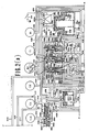
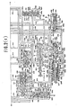
- This hydraulic control system comprises a regulator valve 2, a manual valve 4, a throttle valve 6, a throttle fail safe valve 8, a throttle modulator valve 10, a pressure modifier valve 12, a cut back valve 14, a line pressure booster valve 16, a governor valve 18, a 1-2 shift valve 20, a 2-3 shift valve 22, a 3-4 shift valve 24, a 2-4 timing valve 26, a 2-3 timing valve 28, a 3-4 timing valve 30, a 3-2 timing valve 32, a first manual range pressure reducing valve 34, a torque converter pressure reducing valve 36, a 1-2 accumulator 38, a 4-3 accumulator 40, an overdrive inhibitor solenoid 42, and a centrifugal force offset valve 44 (see Fig. 3). These valves are interconnected as shown in Figs.
- the brake B2 has a servo apply chamber S/A, i.e., a fluid pressure chamber designed to apply the brake when pressurized, and a servo release chamber S/R, i.e., a fluid pressure chamber designed to release the brake when pressurized.
- the brake B2 is released when the pressure is supplied to the servo release chamber S/R irrespective of the supply of fluid pressure to the servo apply chamber S/A.
- the overdrive inhibitor solenoid 42 is electrically connected with an overdrive inhibitor switch SW.
- the names of parts denoted by the reference numerals in Figs. 2(a), 2(b) and 2(c) are hereinafter listed.
- the reference numerals 102, 104, 106, 108, 110, 112, 114, 116, 120, 122, 124, 126, 128, 130, 132, 1334 and 136 denote valve bores, the reference numerals 102a ⁇ j, 104a ⁇ f, 106a ⁇ f, 108a ⁇ e, 110a ⁇ e, 112a ⁇ e, 114a ⁇ g, 116a ⁇ f, 120a ⁇ k, 122a ⁇ j, 124a ⁇ k, 126a ⁇ e, 130a ⁇ e, 132a ⁇ e, and 136a ⁇ e ports, the reference numerals 138 and 140 cylinder bores, the reference numerals 202, 203, 204, 206, 210, 212, 214, 215, 216, 220, 221, 222, 224, 226, 228, 230, 232
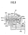
- the centrifugal force offset valve 44 embodying the present invention comprises a valve bore 902 having five ports 902a to 902g, a valve member in the form of a spool 904 having four lands 904a to 904d (the lands 904b and 904c are of the same diameter and the lands 904a and 904d are of smaller diameter than the former two), and a spring 906 biasing the spool 904 to the left as viewed in Fig. 3.
- the ports 902a and 902d communicate with each other by a fluid conduit 462, and the port 902d communicates with the clutch C3 via a fluid conduit 464.
- the port 902b communicates with a fluid conduit 430 which defines a part of a governor pressure circuit.
- the port 902c and port 902f communicate with a fluid conduit 442.
- This fluid conduit 442 communicates with the 3-4 shift valve 24 and is always supplied with fluid pressure to establish first, second and third speed ratios.
- the ports 902e and 902g are drain ports, respectively.
- the clutch C2 and brake B2 are actuated in the fourth speed ratio.
- the clutch drum of the clutch C3 rotates at high speeds and is subject to a centrifugal force which is proportional to the square of the rotational speed of the clutch drum.
- the 3-4 shift valve 24 (see Fig. 2(b)) shifts from an upshift position thereof, as illustrated by the left half thereof in Fig. 2(b), to a downshift position thereof, as illustrated by the right half thereof in Fig. 2(b), the fluid pressure (line pressure) is supplied to the fluid conduit 442.
- the fluid pressure Pr decreases as the governor pressure PG increases.
- the governor pressure is proportional to the square of the rotational speed of the output shaft 0 and the rotational speed of the output shaft 0 is proportional to the rotational speed of the clutch drum of the clutch C3.
- the fluid pressure Pr decreases as a function of the square of the rotational speed of the clutch drum. Since the fluid pressure created within the clutch drum by the centrifugal force is proportional to the square of the rotational speed of the clutch drum, the above mentioned fluid pressure Pr decreases as the centrifugal force increases.
- the present invention has been applied to the four speed automatic transmission, the present invention may be applied to any asutomatic transmission as long as it has a clutch which is engageable when its clutch drum is rotating.
Landscapes
- Engineering & Computer Science (AREA)
- General Engineering & Computer Science (AREA)
- Mechanical Engineering (AREA)
- Physics & Mathematics (AREA)
- Fluid Mechanics (AREA)
- Control Of Transmission Device (AREA)
- Hydraulic Clutches, Magnetic Clutches, Fluid Clutches, And Fluid Joints (AREA)
Claims (1)
- Dispositif de commande hydraulique pour transmission automatique de véhicule à moteur ayant un moteur comportant une vanne papillon qui s'ouvre par degrés, la transmission étant déplaçable entre une pluralité de rapports de vitesse vers l'avant, le dispositif de commande hydraulique comprenant :
une source de fluide pressurisé (2);
des moyens de communication avec cette source de fluide pressurisé pour produire une pression de fluide gouvernant changeant avec la vitesse du véhicule;
des moyens communiquant avec la source de fluide pressurisé variant avec le degré d'ouverture du papillon;
des moyens pour produire un signal de maintien de rétrogradage du fluide pressurisé;
une soupape de changement (24) comportant des moyens pour définir un orifice de soupape, une bobine (224) disposée de façon coulissante à l'intérieur de l'orifice de soupape pour se déplacer entre une position de rétrogradage et une position de changement de vitesse à la volée et ayant au moins une aire d'action de pression qui est exposée à la pression de fluide de gouvernage, un plot (225) ayant une aire d'action de la pression qui est exposée à la pression de fluide de papillon et un ressort (324) disposé entre ladite bobine (224) et ledit plot (225) et agissant entre ceux-ci, l'aire d'action de la pression de gouvernage, lorsqu'elle est actionnée par la pression de gouvernage sollicitant la bobine (224) de manière à déplacer celle-ci depuis sa position de rétrogradage vers sa position de changement à la volée à l'encontre du ressort, cette aire d'action de la pression de papillon, lorsqu'elle est actionnée par la pression de fluide de papillon, sollicitant le plot pour déplacer la bobine (224) depuis sa position de changement à la volée vers la position de rétrogradage de celle-ci;
la bobine (224) ayant une première aire d'action de pression de signal et le plot (225) ayant une seconde aire d'action de la pression de signal;
ledit moyen définissant un orifice de soupape étant formé avec un premier groupe de lumières comprenant une première (124c) une seconde (124d), et une troisième (124e) lumières, ainsi qu'un second groupe de lumières comprenant une quatrième (124f), une cinquième (124g) et une sixième (124h) lumières, la bobine (224) étant formée avec un premier (224a), un second (224b), et un troisième (224c) espaces de commande espacés axialement et coopérant avec le premier groupe de lumières (124c, 124d, 124e) afin de connecter la seconde lumière (124d) sélectivement à l'une des première ou troisième lumière (124c, 124e), les second et troisième espaces de commande (124b, 124c) coopérant avec le second groupe de lumières (124f, 124g, 124h) afin de connecter la cinquième lumière (124g) sélectivement à la quatrième ou à la sixième lumière (124f, 124h), le moyen définissant un perçage de soupape étant formé avec une lumière de sollicitation (124h) débouchant à l'intérieur du perçage de soupape, cette lumière de sollicitation permettant la communication entre le moyen de production de la pression de fluide de signal du signal de maintien de rétrogradage (8) et les première et seconde aires d'action de pression de signal afin de permettre à la pression de fluide du signal de maintien de position de rétrogradage (pression de rétrogradage en ligne rapide 418) d'agir sur les première et seconde aires d'action de pression de signal, ladite première aire d'action de signal de pression, lorsqu'on agit dessus par la pression de fluide de signal de maintien de position de rétrogradage, sollicitant la bobine pour déplacer celle-ci depuis la position de changement à la volée de celle-ci vers la position de rétrogradage de celle-ci, la seconde aire d'action de la pression de signal sollicitant le plot à se déplacer à distance de la bobine lorsqu'on agit dessus sous l'effet de la pression de fluide du signal de maintien de position de rétrogradage,
caractérisé en ce que ladite bobine (224) comprend ladite position de rétrogradage, le premier espace de commande (224a) fermant la première lumière (124c) et le second espace de commande (224b) fermant la quatrième lumière (124f) et les premier et second espaces de commande (224a, 224b) coopérant l'un avec l'autre pour permettre une communication de fluide entre les seconde et troisième lumières (124d, 124e) et le troisième espace de commande (124c) coopérant avec le second espace de commande (224b) pour permettre une communication de fluide entre les cinquième et sixième lumières (124g, 124h), alors que quand la bobine (224) est en position de changement à la volée, le second espace de commande (224b) ferme la troisième lumière (124e) et coopère avec le premier espace de commande (224a) pour permettre une communication de fluide entre les seconde et première lumières (124d, 124c) et le troisième espace de commande (224c) fermant la sixième lumière (124h) et coopérant avec le second espace de commande (224b) pour permettre une communication de fluide entre les quatrième et cinquième lumières (124f, 124g), la première lumière (124c) communiquant avec la quatrième lumière (124f) via un conduit (442) de sorte que la seconde lumière (224d) peut communiquer avec la quatrième lumière (124f) via la première lumière (124c), le conduit (442) et la cinquième lumière (124g) avec la quatrième lumière (124d) et dans le plot (225) comprend un perçage central à l'intérieur duquel le ressort (324) et une extrémité de la bobine (224) sont situés.
Applications Claiming Priority (2)
| Application Number | Priority Date | Filing Date | Title |
|---|---|---|---|
| JP57143288A JPH0625594B2 (ja) | 1982-08-20 | 1982-08-20 | 自動変速機の油圧制御装置 |
| JP143288/82 | 1982-08-20 |
Related Parent Applications (1)
| Application Number | Title | Priority Date | Filing Date |
|---|---|---|---|
| EP83108138.5 Division | 1983-08-17 |
Publications (2)
| Publication Number | Publication Date |
|---|---|
| EP0305595A1 EP0305595A1 (fr) | 1989-03-08 |
| EP0305595B1 true EP0305595B1 (fr) | 1991-10-30 |
Family
ID=15335237
Family Applications (6)
| Application Number | Title | Priority Date | Filing Date |
|---|---|---|---|
| EP19870104235 Expired - Lifetime EP0253952B1 (fr) | 1982-08-20 | 1983-08-17 | Système de commande hydraulique pour transmission |
| EP19870117607 Expired EP0306558B1 (fr) | 1982-08-20 | 1983-08-17 | Transmission automatique |
| EP19870117578 Expired - Lifetime EP0307511B1 (fr) | 1982-08-20 | 1983-08-17 | Transmission automatique |
| EP19870117606 Expired - Lifetime EP0305595B1 (fr) | 1982-08-20 | 1983-08-17 | Système de commande hydraulique pour transmission automatique |
| EP83108138A Expired EP0103751B1 (fr) | 1982-08-20 | 1983-08-17 | Commande hydraulique pour transmission automatique |
| EP19870117579 Expired - Lifetime EP0305594B1 (fr) | 1982-08-20 | 1983-08-17 | Système de commande hydraulique pour transmission automatique |
Family Applications Before (3)
| Application Number | Title | Priority Date | Filing Date |
|---|---|---|---|
| EP19870104235 Expired - Lifetime EP0253952B1 (fr) | 1982-08-20 | 1983-08-17 | Système de commande hydraulique pour transmission |
| EP19870117607 Expired EP0306558B1 (fr) | 1982-08-20 | 1983-08-17 | Transmission automatique |
| EP19870117578 Expired - Lifetime EP0307511B1 (fr) | 1982-08-20 | 1983-08-17 | Transmission automatique |
Family Applications After (2)
| Application Number | Title | Priority Date | Filing Date |
|---|---|---|---|
| EP83108138A Expired EP0103751B1 (fr) | 1982-08-20 | 1983-08-17 | Commande hydraulique pour transmission automatique |
| EP19870117579 Expired - Lifetime EP0305594B1 (fr) | 1982-08-20 | 1983-08-17 | Système de commande hydraulique pour transmission automatique |
Country Status (3)
| Country | Link |
|---|---|
| EP (6) | EP0253952B1 (fr) |
| JP (1) | JPH0625594B2 (fr) |
| DE (5) | DE3382446D1 (fr) |
Families Citing this family (8)
| Publication number | Priority date | Publication date | Assignee | Title |
|---|---|---|---|---|
| JPS59155652A (ja) * | 1983-02-25 | 1984-09-04 | Nissan Motor Co Ltd | 自動変速機の油圧制御装置 |
| JPS6081550A (ja) * | 1983-10-07 | 1985-05-09 | Nissan Motor Co Ltd | 自動変速機の油圧制御装置 |
| US4911117A (en) * | 1987-07-14 | 1990-03-27 | Mazda Motor Corporation | Arrangements for supporting crankshafts in multicylinder engines |
| JPH071025B2 (ja) * | 1988-04-05 | 1995-01-11 | マツダ株式会社 | エンジンのシリンダブロック補強装置 |
| US5154099A (en) * | 1990-10-15 | 1992-10-13 | Honda Giken Kogyo Kabushiki Kaisha | Hydraulic control device for an automatic automotive transmission system |
| JP2767366B2 (ja) * | 1993-08-30 | 1998-06-18 | 本田技研工業株式会社 | 車両用油圧作動式変速機の制御装置 |
| US5967936A (en) * | 1997-02-06 | 1999-10-19 | Kia Motors Corporation | Automatic variable transmission and hydraulic control system thereof |
| JP4461997B2 (ja) | 2004-10-12 | 2010-05-12 | 日産自動車株式会社 | エンジンの制御装置 |
Family Cites Families (17)
| Publication number | Priority date | Publication date | Assignee | Title |
|---|---|---|---|---|
| US3656373A (en) * | 1968-10-31 | 1972-04-18 | Tetsuo Shimosaki | Control system for an automatic transmission |
| GB1267423A (en) * | 1969-04-25 | 1972-03-22 | Borg Warner Ltd | Transmission control mechanism |
| US3685372A (en) * | 1970-05-19 | 1972-08-22 | Nissan Motor | Automatic transmission |
| JPS4838578B1 (fr) * | 1970-12-18 | 1973-11-19 | ||
| US3744348A (en) * | 1971-06-01 | 1973-07-10 | Borg Warner | Planetary transmission mechanism and hydraulic control |
| US3855880A (en) * | 1971-11-26 | 1974-12-24 | Nissan Motor | Hydraulic pressure control system for an automatic power transmission |
| JPS5231914Y2 (fr) * | 1973-09-21 | 1977-07-20 | ||
| DE2352939C2 (de) * | 1973-10-23 | 1984-07-05 | Robert Bosch Gmbh, 7000 Stuttgart | Hydraulische Steuervorrichtung, insbesondere für eine Gangwechseleinrichtung in automatischen Kraftfahrzeuggetrieben |
| JPS5174167A (en) * | 1974-12-23 | 1976-06-26 | Toyota Motor Co Ltd | Jidohensokukino yuatsuseigyosochi |
| US4071126A (en) * | 1974-12-24 | 1978-01-31 | Torao Hattori | Safety apparatus in an automatic transmission for a vehicle to prevent engagement of the low speed clutch at high speeds |
| JPS5828458B2 (ja) * | 1975-09-25 | 1983-06-16 | トヨタ自動車株式会社 | ジドウヘンソクキノ ユアツセイギヨソウチ |
| DE2846904A1 (de) * | 1978-02-09 | 1979-08-16 | Gen Motors Corp | Getriebe mit einer zugeordneten druckfluessigkeitsquelle veraenderlicher foerdermenge |
| DE2832345C2 (de) * | 1978-07-22 | 1986-12-04 | Volkswagen AG, 3180 Wolfsburg | Hydraulische Steuervorrichtung für ein automatisches Kraftfahrzeug-Wechselgetriebe |
| JPS5945862B2 (ja) * | 1978-08-07 | 1984-11-09 | 日産自動車株式会社 | 自動変速機のシヨツク軽減装置 |
| JPS5949452B2 (ja) * | 1978-10-03 | 1984-12-03 | 日産自動車株式会社 | 自動変速機のライン圧制御装置 |
| US4347765A (en) * | 1979-10-05 | 1982-09-07 | Ford Motor Company | Multiple ratio overdrive transmission |
| US4430910A (en) * | 1981-06-08 | 1984-02-14 | Ford Motor Company | Clutch control valve for an automatic transmission control circuit |
-
1982
- 1982-08-20 JP JP57143288A patent/JPH0625594B2/ja not_active Expired - Lifetime
-
1983
- 1983-08-17 EP EP19870104235 patent/EP0253952B1/fr not_active Expired - Lifetime
- 1983-08-17 DE DE8787117606T patent/DE3382446D1/de not_active Expired - Fee Related
- 1983-08-17 EP EP19870117607 patent/EP0306558B1/fr not_active Expired
- 1983-08-17 DE DE8787104235T patent/DE3382444D1/de not_active Expired - Fee Related
- 1983-08-17 DE DE8787117578T patent/DE3382490D1/de not_active Expired - Fee Related
- 1983-08-17 EP EP19870117578 patent/EP0307511B1/fr not_active Expired - Lifetime
- 1983-08-17 EP EP19870117606 patent/EP0305595B1/fr not_active Expired - Lifetime
- 1983-08-17 EP EP83108138A patent/EP0103751B1/fr not_active Expired
- 1983-08-17 EP EP19870117579 patent/EP0305594B1/fr not_active Expired - Lifetime
- 1983-08-17 DE DE8787117579T patent/DE3382445D1/de not_active Expired - Fee Related
- 1983-08-17 DE DE8787117607T patent/DE3382316D1/de not_active Expired - Fee Related
Also Published As
| Publication number | Publication date |
|---|---|
| DE3382444D1 (de) | 1991-12-05 |
| DE3382446D1 (de) | 1991-12-05 |
| EP0307511A1 (fr) | 1989-03-22 |
| EP0103751A3 (en) | 1985-04-24 |
| DE3382490D1 (de) | 1992-02-13 |
| EP0103751A2 (fr) | 1984-03-28 |
| EP0307511B1 (fr) | 1992-01-02 |
| EP0253952A2 (fr) | 1988-01-27 |
| EP0103751B1 (fr) | 1989-07-12 |
| JPH0625594B2 (ja) | 1994-04-06 |
| JPS5934049A (ja) | 1984-02-24 |
| EP0306558B1 (fr) | 1991-06-12 |
| EP0253952B1 (fr) | 1991-10-30 |
| EP0305594A1 (fr) | 1989-03-08 |
| EP0305594B1 (fr) | 1991-10-30 |
| DE3382316D1 (de) | 1991-07-18 |
| EP0305595A1 (fr) | 1989-03-08 |
| EP0306558A1 (fr) | 1989-03-15 |
| EP0253952A3 (en) | 1988-07-06 |
| DE3382445D1 (de) | 1991-12-05 |
Similar Documents
| Publication | Publication Date | Title |
|---|---|---|
| US4308765A (en) | Line pressure control device for the hydraulic control system of an automatic power transmission | |
| JPS5948897B2 (ja) | 自動変速機の変速シヨツク軽減装置 | |
| US4474084A (en) | Shift device of hydraulic control system for automatic transmission | |
| US4446759A (en) | Clutch stroke control metering valve for an automatic transmission | |
| EP0305595B1 (fr) | Système de commande hydraulique pour transmission automatique | |
| EP0059427B1 (fr) | Dispositif de passage d'un système de commande hydraulique pour une transmission automatique | |
| GB2033504A (en) | Device preventing simultaneous engagement of two ratios in an automatic transmission | |
| US3896685A (en) | Transmission control for a transmission having one drive establishing device for two independent drive functions | |
| US4462280A (en) | Manual valve for hydraulic control system for automatic transmission | |
| EP0123047B1 (fr) | Système de commande hydraulique pour transmission automatique avec changement de vitesse 4-3 et 4-2 sans choc | |
| US4724727A (en) | Hydraulic control system for automatic transmission | |
| EP0058414B1 (fr) | Contrôle hydraulique pour transmission automatique | |
| US4595088A (en) | Hydraulic control system for lock-up clutch | |
| US3405575A (en) | Automatic control valve system for a multiple ratio power transmission mechanism | |
| US4867014A (en) | Accumulator/friction element arrangement for automatic transmission | |
| US5005443A (en) | Shift control system for automatic transmission | |
| JPS5948899B2 (ja) | 自動変速機のシフトバルブ | |
| US4585100A (en) | Hydraulic control system for automatic transmission having torque converter with lock-up mechanism | |
| US5016496A (en) | Shift control system for engine braking in an auxiliary transmission | |
| EP0136370B1 (fr) | Système de commande hydraulique pour embrayage de pontage | |
| US4951528A (en) | Shift control system for automatic transmission | |
| JPH0547744B2 (fr) | ||
| JPH0236828B2 (fr) | ||
| JPS6026838A (ja) | 自動変速機の油圧制御装置 | |
| JPH07103931B2 (ja) | 自動変速機のバンドサーボ装置 |
Legal Events
| Date | Code | Title | Description |
|---|---|---|---|
| PUAI | Public reference made under article 153(3) epc to a published international application that has entered the european phase |
Free format text: ORIGINAL CODE: 0009012 |
|
| 17P | Request for examination filed |
Effective date: 19880920 |
|
| AC | Divisional application: reference to earlier application |
Ref document number: 103751 Country of ref document: EP |
|
| AK | Designated contracting states |
Kind code of ref document: A1 Designated state(s): DE FR GB |
|
| 17Q | First examination report despatched |
Effective date: 19890623 |
|
| GRAA | (expected) grant |
Free format text: ORIGINAL CODE: 0009210 |
|
| AC | Divisional application: reference to earlier application |
Ref document number: 103751 Country of ref document: EP |
|
| AK | Designated contracting states |
Kind code of ref document: B1 Designated state(s): DE FR GB |
|
| REF | Corresponds to: |
Ref document number: 3382446 Country of ref document: DE Date of ref document: 19911205 |
|
| ET | Fr: translation filed | ||
| PLBE | No opposition filed within time limit |
Free format text: ORIGINAL CODE: 0009261 |
|
| STAA | Information on the status of an ep patent application or granted ep patent |
Free format text: STATUS: NO OPPOSITION FILED WITHIN TIME LIMIT |
|
| 26N | No opposition filed | ||
| PG25 | Lapsed in a contracting state [announced via postgrant information from national office to epo] |
Ref country code: FR Effective date: 19930430 |
|
| REG | Reference to a national code |
Ref country code: FR Ref legal event code: ST |
|
| PGFP | Annual fee paid to national office [announced via postgrant information from national office to epo] |
Ref country code: GB Payment date: 19990811 Year of fee payment: 17 |
|
| PGFP | Annual fee paid to national office [announced via postgrant information from national office to epo] |
Ref country code: DE Payment date: 19990823 Year of fee payment: 17 |
|
| PG25 | Lapsed in a contracting state [announced via postgrant information from national office to epo] |
Ref country code: GB Free format text: LAPSE BECAUSE OF NON-PAYMENT OF DUE FEES Effective date: 20000817 |
|
| GBPC | Gb: european patent ceased through non-payment of renewal fee |
Effective date: 20000817 |
|
| PG25 | Lapsed in a contracting state [announced via postgrant information from national office to epo] |
Ref country code: DE Free format text: LAPSE BECAUSE OF NON-PAYMENT OF DUE FEES Effective date: 20010501 |