EP0305584A2 - Procédé de traitement des gaz d'échappement, en particulier pour leur neutralisation - Google Patents
Procédé de traitement des gaz d'échappement, en particulier pour leur neutralisation Download PDFInfo
- Publication number
- EP0305584A2 EP0305584A2 EP87114467A EP87114467A EP0305584A2 EP 0305584 A2 EP0305584 A2 EP 0305584A2 EP 87114467 A EP87114467 A EP 87114467A EP 87114467 A EP87114467 A EP 87114467A EP 0305584 A2 EP0305584 A2 EP 0305584A2
- Authority
- EP
- European Patent Office
- Prior art keywords
- raw material
- exhaust gases
- exhaust gas
- glass
- material mixture
- Prior art date
- Legal status (The legal status is an assumption and is not a legal conclusion. Google has not performed a legal analysis and makes no representation as to the accuracy of the status listed.)
- Withdrawn
Links
- 238000000034 method Methods 0.000 title claims abstract description 26
- 230000008569 process Effects 0.000 title abstract description 5
- 238000006386 neutralization reaction Methods 0.000 title description 9
- 239000002912 waste gas Substances 0.000 title 1
- 239000007789 gas Substances 0.000 claims abstract description 81
- 239000000203 mixture Substances 0.000 claims abstract description 50
- 239000002994 raw material Substances 0.000 claims abstract description 49
- 239000011521 glass Substances 0.000 claims abstract description 43
- 239000003344 environmental pollutant Substances 0.000 claims abstract description 15
- 238000002844 melting Methods 0.000 claims abstract description 15
- 230000008018 melting Effects 0.000 claims abstract description 15
- 231100000719 pollutant Toxicity 0.000 claims abstract description 15
- 238000004519 manufacturing process Methods 0.000 claims abstract description 8
- 239000002699 waste material Substances 0.000 claims abstract description 7
- 230000003472 neutralizing effect Effects 0.000 claims abstract description 4
- 239000002245 particle Substances 0.000 claims description 16
- 239000007787 solid Substances 0.000 claims description 12
- 239000000428 dust Substances 0.000 claims description 7
- 239000000126 substance Substances 0.000 claims description 5
- 230000005684 electric field Effects 0.000 claims description 4
- 239000000654 additive Substances 0.000 claims description 3
- 239000000779 smoke Substances 0.000 claims description 2
- 239000007788 liquid Substances 0.000 claims 1
- 239000003595 mist Substances 0.000 claims 1
- 239000003546 flue gas Substances 0.000 abstract description 3
- 230000009467 reduction Effects 0.000 abstract description 3
- 238000003912 environmental pollution Methods 0.000 abstract 1
- 239000012717 electrostatic precipitator Substances 0.000 description 5
- XLYOFNOQVPJJNP-UHFFFAOYSA-N water Substances O XLYOFNOQVPJJNP-UHFFFAOYSA-N 0.000 description 5
- 238000002485 combustion reaction Methods 0.000 description 2
- 238000001816 cooling Methods 0.000 description 2
- 239000000156 glass melt Substances 0.000 description 2
- 230000007257 malfunction Effects 0.000 description 2
- 238000000926 separation method Methods 0.000 description 2
- 230000035508 accumulation Effects 0.000 description 1
- 238000009825 accumulation Methods 0.000 description 1
- 230000001174 ascending effect Effects 0.000 description 1
- 230000008901 benefit Effects 0.000 description 1
- 230000008859 change Effects 0.000 description 1
- 239000003795 chemical substances by application Substances 0.000 description 1
- 239000006063 cullet Substances 0.000 description 1
- 238000010586 diagram Methods 0.000 description 1
- 230000007613 environmental effect Effects 0.000 description 1
- 238000010304 firing Methods 0.000 description 1
- 239000012634 fragment Substances 0.000 description 1
- 239000006066 glass batch Substances 0.000 description 1
- 238000010438 heat treatment Methods 0.000 description 1
- 238000010309 melting process Methods 0.000 description 1
- 238000000746 purification Methods 0.000 description 1
- 230000001172 regenerating effect Effects 0.000 description 1
Images


Classifications
-
- C—CHEMISTRY; METALLURGY
- C03—GLASS; MINERAL OR SLAG WOOL
- C03B—MANUFACTURE, SHAPING, OR SUPPLEMENTARY PROCESSES
- C03B5/00—Melting in furnaces; Furnaces so far as specially adapted for glass manufacture
- C03B5/16—Special features of the melting process; Auxiliary means specially adapted for glass-melting furnaces
- C03B5/235—Heating the glass
- C03B5/237—Regenerators or recuperators specially adapted for glass-melting furnaces
-
- B—PERFORMING OPERATIONS; TRANSPORTING
- B01—PHYSICAL OR CHEMICAL PROCESSES OR APPARATUS IN GENERAL
- B01D—SEPARATION
- B01D53/00—Separation of gases or vapours; Recovering vapours of volatile solvents from gases; Chemical or biological purification of waste gases, e.g. engine exhaust gases, smoke, fumes, flue gases, aerosols
- B01D53/34—Chemical or biological purification of waste gases
-
- C—CHEMISTRY; METALLURGY
- C03—GLASS; MINERAL OR SLAG WOOL
- C03B—MANUFACTURE, SHAPING, OR SUPPLEMENTARY PROCESSES
- C03B3/00—Charging the melting furnaces
- C03B3/02—Charging the melting furnaces combined with preheating, premelting or pretreating the glass-making ingredients, pellets or cullet
- C03B3/023—Preheating
-
- Y—GENERAL TAGGING OF NEW TECHNOLOGICAL DEVELOPMENTS; GENERAL TAGGING OF CROSS-SECTIONAL TECHNOLOGIES SPANNING OVER SEVERAL SECTIONS OF THE IPC; TECHNICAL SUBJECTS COVERED BY FORMER USPC CROSS-REFERENCE ART COLLECTIONS [XRACs] AND DIGESTS
- Y02—TECHNOLOGIES OR APPLICATIONS FOR MITIGATION OR ADAPTATION AGAINST CLIMATE CHANGE
- Y02P—CLIMATE CHANGE MITIGATION TECHNOLOGIES IN THE PRODUCTION OR PROCESSING OF GOODS
- Y02P40/00—Technologies relating to the processing of minerals
- Y02P40/50—Glass production, e.g. reusing waste heat during processing or shaping
Definitions
- the invention relates to a process for the treatment of exhaust gases from glass production, in particular for the neutralization of smoke gases from a glass melting tank.
- the invention is based on the object of creating a method which enables simple (economical) treatment of the exhaust gases to be released into the atmosphere, in particular neutralization of at least the particularly questionable pollutant components.
- the method according to the invention is characterized in that the exhaust gases are passed through a mixture of raw materials consisting at least partially of waste glass (broken glass). It has surprisingly been found that the raw material mixture at least partially eliminates the pollutant components in the exhaust gases. In particular, the pollutant components are eliminated by the waste glass contained in the raw material mixture, preferably from a mixture of broken glass. Pollutants contained in the exhaust gas, such as HCL, HF, SO2, SO3, CO and possibly NO x , can be completely or partially eliminated from the exhaust gas by neutralization.
- the process according to the invention is particularly economical because, simultaneously with the treatment of the exhaust gases, the raw material mixture is preheated to about 250 ° to 350 ° C. (starting from the ambient temperature).
- the residual energy contained in the exhaust gas can still be used sensibly, in that the exhaust gases are only introduced into the atmosphere at a residual temperature of 180 ° to 220 ° C (compared to previously 400 ° to 500 ° C).
- Another advantage of the process according to the invention is that no neutralizing agents which are foreign to the glass production process are required for neutralization.
- the exhaust gases are passed through a fixed bed of the raw material mixture, expediently in countercurrent flow.
- This enables particularly intensive contact between the exhaust gases to be treated and the raw material mixture, in particular the broken glass of the waste glass mixture. It is also achieved in this way that passing the exhaust gases through the raw material mixture does not require any considerable additional energy expenditure, since the raw material mixture can be accommodated in a silo or bunker-like container during the treatment of the exhaust gas, in which the raw material mixture is drawn off on the underside and a corresponding filling from above of the container, a normally even, gradual flow of the broken glass mixture through the same takes place.
- Electrostatic filters are particularly suitable for eliminating the solid particles from the (cooled) exhaust gas.
- a plurality of electrostatic filters connected in series with different electrical fields are preferably used. It has surprisingly been found that the dust particles deposited in the individual electrostatic filters with different electric fields have different chemical accumulations, which come primarily from the neutralization in the raw material mixture. As a result, the further processing of the separated particles from the respective electrostatic filter may take place differently.
- the method according to the invention is described below using a plant for glass production.
- the system shown in FIG. 1 has a glass melting trough 10 which has burners 12 in its vaulted ceiling for heating the glass melt 13 located in the glass melting trough 10.
- the burners 12 are usually fed by two alternately operated regenerators 14 which are oil or gas-fired.
- the exhaust gases from the glass melting tank 10 are in turn passed through the alternately operated regenerators 14 for preheating fresh combustion air.
- the exhaust pipes 15 of both regenerators 14 are guided to a control valve 16, from where the exhaust gases are passed on in a manner described below.
- a raw material mixture 17 is fed to the glass melting tank 10 to form the glass melt 13.
- This is composed of a mixture of (fresh) raw materials for glass production and waste glass, namely in particular broken glass 20.
- the proportion of broken glass 20 or a broken glass mixture can be up to 90% of the raw material mixture 17.
- the (fresh) batch 19 and the broken glass 20 are fed to an intermediate bunker 18 to form the raw material batch 17.
- the batch 19 can be mixed with the broken glass 20 in the intermediate bunker 18.
- the resulting largely homogeneous raw Mixture 17 is then passed via a chain of several conveyors 21, shown schematically in FIG. 1, to the top of a bunker arranged downstream of the intermediate bunker 18, which is designed here as a preheating bunker 22.
- the preheated raw material batch 17 leaves this preheater bunker 22, which is explained in more detail below with reference to FIGS. 2 and 3, at a lower outlet funnel 23, from which the raw material batch 17 reaches the glass melting tank 10 via a further conveyor 24.
- the exhaust gases coming from the regenerators 14 are directed from the control valve 16 via a feed line 25 into the lower region of the preheating bunker 22.
- the exhaust gas In the ascending direction, namely in cross-countercurrent, the exhaust gas is passed through the preheating bunker 22 in several floors (channel levels), the exhaust gas leaving the preheating bunker 22 in the upper region.
- the exhaust gas When flowing through the preheating bunker 22 through the exhaust gas, on the one hand, the exhaust gas is neutralized, preferably by reducing pollutant components, namely HCL, HF, SO2, SO3, CO and NO x , which occur during combustion in the glass melting tank 10, completely or at least as far as possible that the remaining proportion of these pollutant components is below the legally prescribed limit values. Furthermore, the exhaust gas is cooled as it flows through the preheating bunker 22 from an inlet temperature between 400 ° and 500 ° C. to an outlet temperature of about 140 ° to 180 ° C. The raw material mixture 17 which is gradually passed through the preheating bunker 22 from top to bottom is preheated by the exhaust gases from room temperature to about 250 ° - 300 ° C.
- pollutant components namely HCL, HF, SO2, SO3, CO and NO x
- the exhaust gases emerging from the preheating bunker 22 can be controlled by corresponding control valves 27 in the supply line 25, in a discharge line 28 for the exhaust gases from the preheating Bunker 22 and a connecting line 29 between the feed line 25 and the discharge line 28 are controlled so that the exhaust gases can be discharged bypassing the preheating bunker 22 in the event of a short-term malfunction in the preheating bunker 22.
- a bypass line 30 is assigned to the feed line 25 in the present exemplary embodiment, which opens below the feed line 25 in the preheating bunker 22 and which enables a blower 31 for introducing the exhaust gas coming into the preheating bunker 22 via the bypass line 30 to maintain an upright flow of the exhaust gases in the Preheating bunker 22.
- Water containing additives can be sprinkled.
- the water is circulated by a circulation pump 34 in a closed water circuit 33 (dash-dotted lines) through a reservoir 35 which serves to cool the water heated in the cooler 32.
- the cooler 32 is also used for the complete cooling of the (hot) exhaust gases which are briefly conducted in the preheating bunker 22 in the event of malfunctions in the preheating bunker 22 and the discharge line 28.
- chemical additives in the water of the cooler 32 can be used instead of the neutralization of the exhaust gases which then does not take place in the preheating bunker 22.
- the exhaust gases From the cooler 32, the exhaust gases finally reach an electrostatic precipitator system 37.
- this consists of three electrostatic filters 38, 39, 40 arranged one behind the other.
- electrostatic filters 38.40 there is a (dry) off separation of small solid particles in the exhaust gases.
- these are the smallest cullet particles from the preheating bunker 22, which are entrained when the exhaust gases are passed through them.
- the three electrostatic filters 38, 39 and 40 are assigned a return line 42 (dashed line) through which the separated solid particles (dust) can be returned, in the present exemplary embodiment to the conveyor 24, which is also used to discharge the from the preheating bunker 22 withdrawn preheated raw material mixture 17 to the glass melting tank 10 is used.
- a suction fan 43 Downstream of the electrostatic filters 38..40 is a suction fan 43 which directs the exhaust gases treated according to the invention with overpressure through a return line 42 into a corresponding chimney 44 through which the exhaust gases can be fed to the atmosphere.
- a further bypass line 45 branches off from the supply line 25 of the exhaust gas to the preheating bunker 22 above the control valve 16 and opens directly into the chimney 44 via an intermediate suction fan 46. This makes it possible to continue operating the glass melting process in the glass melting tank 10 for a short time if, for some reason, it is not possible to discharge the exhaust gases through the preheating bunker 22. This diversion of the exhaust gases is controlled by corresponding control valves 47 in the feed line 25, the bypass line 45 and the return line 42.
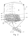
- the preheating bunker 22 has an approximately square cross section made up of four upright side walls 48. In the lower region, the preheating bunker 22 is narrowed in a funnel shape towards the outlet 49. A large number of horizontal flow channels 50 are located in the main part of the preheating bunker 22. These are located in horizontal channel levels 51 lying one above the other. In the present exemplary embodiment, eight channel levels 51 are each formed from three flow channels 50 in the preheating bunker 22. The flow channels 50 of the adjacent channel planes 51 are offset from one another, namely they are located on a “gap”.
- the flow channels 50 are distributed approximately uniformly over the interior of the preheating bunker 22.
- the flow channels 50 are connected by overflow channels 52 arranged in the interior of the preheating bunker 22, which here consist of V-profiles connected to the corresponding side walls 48.
- Each flow channel 50 is approximately the same in the present embodiment, and in a particularly simple manner from an elongated, isosceles angle profile 53.
- the arrangement of the angle profiles 53 for the flow channels 50 is such that the two legs 54 of equal length lie at the same angle, namely at approximately 45 °, with an apex edge 55 lying at the top.
- the two parallel, lower free edges 56 of the legs 54 thus lie approximately in a horizontal plane, namely the channel plane 51. Due to this design and arrangement of the flow channels 50 in the preheating bunker 22, they form a roof for the raw material mixture 17, below which a bulk cone forms in the raw material mixture 17.
- flow channels 50 with an approximately square cross section are formed, the boundary surfaces of the lower half of each flow channel 50 being formed directly by the raw material mixture 17.
- arrows 57 also show the downward flow direction of the raw material mixture 17 in the preheating bunker 22. Accordingly, the raw material mixture 17 flows uniformly along an approximately S-shaped course through the flow channels 50 of different channel levels 51. Those portions of the raw material mixture 17 that form the lower boundary surfaces of the flow channels 50 constantly change, which promotes homogeneous preheating of the raw material mixture 17 and a reliable reduction in the exhaust gases, since these always come into contact with "fresh" raw material mixture 17.
Landscapes
- Chemical & Material Sciences (AREA)
- Engineering & Computer Science (AREA)
- Materials Engineering (AREA)
- Organic Chemistry (AREA)
- Health & Medical Sciences (AREA)
- Biomedical Technology (AREA)
- Environmental & Geological Engineering (AREA)
- Analytical Chemistry (AREA)
- General Chemical & Material Sciences (AREA)
- Oil, Petroleum & Natural Gas (AREA)
- Chemical Kinetics & Catalysis (AREA)
- Treating Waste Gases (AREA)
- Waste-Gas Treatment And Other Accessory Devices For Furnaces (AREA)
Applications Claiming Priority (2)
| Application Number | Priority Date | Filing Date | Title |
|---|---|---|---|
| EP87112624 | 1987-08-29 | ||
| EP87112624 | 1987-08-29 |
Publications (2)
| Publication Number | Publication Date |
|---|---|
| EP0305584A2 true EP0305584A2 (fr) | 1989-03-08 |
| EP0305584A3 EP0305584A3 (fr) | 1989-09-20 |
Family
ID=8197234
Family Applications (1)
| Application Number | Title | Priority Date | Filing Date |
|---|---|---|---|
| EP87114467A Withdrawn EP0305584A3 (fr) | 1987-08-29 | 1987-10-03 | Procédé de traitement des gaz d'échappement, en particulier pour leur neutralisation |
Country Status (1)
| Country | Link |
|---|---|
| EP (1) | EP0305584A3 (fr) |
Cited By (7)
| Publication number | Priority date | Publication date | Assignee | Title |
|---|---|---|---|---|
| EP0395789A1 (fr) * | 1989-03-28 | 1990-11-07 | BETEILIGUNGEN SORG GMBH & CO. KG | Procédé pour la purification des gaz d'échappement émis d'un four de fusion |
| EP0552660A1 (fr) * | 1992-01-20 | 1993-07-28 | AVIR FINANZIARIA S.p.A. | Procédé pour la purification des gaz d'échappement émis des fours de fusion |
| EP1123903A3 (fr) * | 2000-01-18 | 2001-11-14 | The BOC Group plc | Préchauffeur électrostatique pour composition de verre |
| WO2011085711A1 (fr) * | 2010-01-18 | 2011-07-21 | Rolf Wenning | Dispositif et procédé pour stabiliser la pression de four dans le cas de quantités de volume de gaz brûlé qui varient lors du changement de chaudière lors de processus de fusion de verre et de processus leuter dans des cuves à flamme transversale avec des chauffages régénératifs |
| WO2012048706A3 (fr) * | 2010-09-26 | 2012-06-21 | Get Glass Engineering Gmbh | Procédé et dispositif permettant l'alimentation en effluents gazeux de process et la régulation du volume des effluents gazeux afin d'améliorer la stabilisation de la pression dans un four dans des process de fonte de verre et de filtration dans des cuves à brûleurs transversaux avec chauffage par récupération |
| CN104797537A (zh) * | 2012-11-15 | 2015-07-22 | 旭硝子株式会社 | 无碱玻璃的制造方法 |
| CN109721223A (zh) * | 2018-12-24 | 2019-05-07 | 郑州旭飞光电科技有限公司 | 一种生产液晶玻璃的方法和系统 |
Family Cites Families (5)
| Publication number | Priority date | Publication date | Assignee | Title |
|---|---|---|---|---|
| GB1429427A (en) * | 1974-07-25 | 1976-03-24 | Asahi Fibreglass Co | Method of cleaning waste gases containing a fluorine component |
| US4410347A (en) * | 1981-03-31 | 1983-10-18 | Ppg Industries, Inc. | Glass melting method using cullet as particulate collection medium |
| DE3416317A1 (de) * | 1984-05-03 | 1985-11-07 | Himly, Holscher GmbH & Co, 3070 Nienburg | Verfahren und vorrichtung zum vorwaermen von rohstoffen fuer die glasherstellung, insbesondere eines glasscherbengemenges |
| DE3605509A1 (de) * | 1986-02-20 | 1987-08-27 | Gruenzweig Hartmann Glasfaser | Verfahren zum erschmelzen von silikatischen rohstoffen, insbesondere zur herstellung von mineralwolle, sowie vorrichtung zur vorwaermung des rohstoffgemenges und reinigungseinrichtung fuer die wannenabgase zur durchfuehrung des verfahrens |
| DE3631729A1 (de) * | 1986-09-18 | 1988-03-24 | Gea Luftkuehler Happel Gmbh | Verfahren zur katalytischen umwandlung von stickstoffoxiden in den bei der glasherstellung anfallenden rauchgasen |
-
1987
- 1987-10-03 EP EP87114467A patent/EP0305584A3/fr not_active Withdrawn
Cited By (11)
| Publication number | Priority date | Publication date | Assignee | Title |
|---|---|---|---|---|
| EP0395789A1 (fr) * | 1989-03-28 | 1990-11-07 | BETEILIGUNGEN SORG GMBH & CO. KG | Procédé pour la purification des gaz d'échappement émis d'un four de fusion |
| EP0552660A1 (fr) * | 1992-01-20 | 1993-07-28 | AVIR FINANZIARIA S.p.A. | Procédé pour la purification des gaz d'échappement émis des fours de fusion |
| AU657025B2 (en) * | 1992-01-20 | 1995-02-23 | Avir Finanziaria S.P.A. | Process for the purification of waste gases emitted from melting furnaces |
| EP1123903A3 (fr) * | 2000-01-18 | 2001-11-14 | The BOC Group plc | Préchauffeur électrostatique pour composition de verre |
| AU772030B2 (en) * | 2000-01-18 | 2004-04-08 | Boc Group Plc, The | Electrostatic batch preheater |
| WO2011085711A1 (fr) * | 2010-01-18 | 2011-07-21 | Rolf Wenning | Dispositif et procédé pour stabiliser la pression de four dans le cas de quantités de volume de gaz brûlé qui varient lors du changement de chaudière lors de processus de fusion de verre et de processus leuter dans des cuves à flamme transversale avec des chauffages régénératifs |
| WO2012048706A3 (fr) * | 2010-09-26 | 2012-06-21 | Get Glass Engineering Gmbh | Procédé et dispositif permettant l'alimentation en effluents gazeux de process et la régulation du volume des effluents gazeux afin d'améliorer la stabilisation de la pression dans un four dans des process de fonte de verre et de filtration dans des cuves à brûleurs transversaux avec chauffage par récupération |
| CN104797537A (zh) * | 2012-11-15 | 2015-07-22 | 旭硝子株式会社 | 无碱玻璃的制造方法 |
| CN104797537B (zh) * | 2012-11-15 | 2017-03-08 | 旭硝子株式会社 | 无碱玻璃的制造方法 |
| CN109721223A (zh) * | 2018-12-24 | 2019-05-07 | 郑州旭飞光电科技有限公司 | 一种生产液晶玻璃的方法和系统 |
| CN109721223B (zh) * | 2018-12-24 | 2021-11-26 | 郑州旭飞光电科技有限公司 | 一种生产液晶玻璃的方法 |
Also Published As
| Publication number | Publication date |
|---|---|
| EP0305584A3 (fr) | 1989-09-20 |
Similar Documents
| Publication | Publication Date | Title |
|---|---|---|
| DE2321881A1 (de) | Verfahren zur entfernung von schwefeloxyden aus verbrennungsabgasen | |
| DE2724372C2 (de) | Verfahren zum Konditionieren von Bypaßgasen | |
| EP0305584A2 (fr) | Procédé de traitement des gaz d'échappement, en particulier pour leur neutralisation | |
| EP0324454B2 (fr) | Procédé et dispositif pour la purification des gaz de fumée | |
| DE3605100C2 (fr) | ||
| AT412533B (de) | Verfahren zur reinigung von abgasen sowie anlage hiefür | |
| EP2248773A1 (fr) | Dispositif de préchauffage des mélanges vitrifiables contentant de calcin | |
| DE3520819A1 (de) | Verfahren zur thermischen behandlung von mit schadstoffen belasteten massen sowie anlage zur durchfuehrung eines solchen verfahrens | |
| DE2737117A1 (de) | Verfahren und vorrichtung zum kontinuierlichen regenerieren von verbrauchtem katalysator | |
| DE3133467C2 (de) | Verfahren zum Vorerhitzen von Glasgemenge in einem Wärmetauscher | |
| DE69117096T3 (de) | Verfahren und Vorrichtung zur Herstellung von Klinker aus mineralischen Rohmaterialien | |
| DE3416317A1 (de) | Verfahren und vorrichtung zum vorwaermen von rohstoffen fuer die glasherstellung, insbesondere eines glasscherbengemenges | |
| EP0211977B1 (fr) | Procédé et appareil pour le préchauffage de matière première pour la fabrication de verre, particulièrement pour bris de verre | |
| DE3410895A1 (de) | Verfahren und anlage zur verminderung des schadstoffgehaltes von rauchgasen | |
| DE4405010A1 (de) | Vorrichtung und Verfahren zur Abgasreinigung | |
| EP0654017A1 (fr) | Procede et dispositif de traitement thermique de dechets et/ou de residus. | |
| DE3041997A1 (de) | Verfahren zur abtrennung von umweltschaedigenden gasen aus rauchgasen, insbesondere von tunneloefen, und vorrichtung zur durchfuehrung des verfahrens | |
| DE4141625A1 (de) | Verfahren zum erschmelzen von silikatischen rohstoffen, insbesondere zur herstellung von mineralwolle, sowie vorrichtung zur vorwaermung des rohstoffgemenges | |
| DE2232258C3 (de) | Verfahren zur Behandlung von schädliche Bestandteile enthaltenden Abgasen aus Industrieanlagen | |
| DE4446575A1 (de) | Verfahren und Vorrichtung zum Abtrennen von Galle bei Schmelzprozessen von Glas | |
| DE3340655A1 (de) | Filtervorrichtung zur abgas- oder wasserfilterung | |
| DE2606272A1 (de) | Verfahren zur beseitigung des feuchtigkeits- und (schmier-)-fettgehalts eines walzwerkschlamms | |
| DE2746331A1 (de) | Verfahren und vorrichtung zum brennen von sintermaterial | |
| DE2234847A1 (de) | Verfahren zur behandlung von stueckigem material in schachtoefen | |
| DE4028112C2 (fr) |
Legal Events
| Date | Code | Title | Description |
|---|---|---|---|
| PUAI | Public reference made under article 153(3) epc to a published international application that has entered the european phase |
Free format text: ORIGINAL CODE: 0009012 |
|
| AK | Designated contracting states |
Kind code of ref document: A2 Designated state(s): AT BE CH DE ES FR GB GR IT LI LU NL SE |
|
| PUAL | Search report despatched |
Free format text: ORIGINAL CODE: 0009013 |
|
| RHK1 | Main classification (correction) |
Ipc: C03B 5/235 |
|
| AK | Designated contracting states |
Kind code of ref document: A3 Designated state(s): AT BE CH DE ES FR GB GR IT LI LU NL SE |
|
| STAA | Information on the status of an ep patent application or granted ep patent |
Free format text: STATUS: THE APPLICATION IS DEEMED TO BE WITHDRAWN |
|
| 18D | Application deemed to be withdrawn |
Effective date: 19900502 |