EP0305584A2 - Process for the treatment, especially for the neutralization of waste gases - Google Patents
Process for the treatment, especially for the neutralization of waste gases Download PDFInfo
- Publication number
- EP0305584A2 EP0305584A2 EP87114467A EP87114467A EP0305584A2 EP 0305584 A2 EP0305584 A2 EP 0305584A2 EP 87114467 A EP87114467 A EP 87114467A EP 87114467 A EP87114467 A EP 87114467A EP 0305584 A2 EP0305584 A2 EP 0305584A2
- Authority
- EP
- European Patent Office
- Prior art keywords
- raw material
- exhaust gas
- material mixture
- glass
- bunker
- Prior art date
- Legal status (The legal status is an assumption and is not a legal conclusion. Google has not performed a legal analysis and makes no representation as to the accuracy of the status listed.)
- Withdrawn
Links
Images


Classifications
-
- C—CHEMISTRY; METALLURGY
- C03—GLASS; MINERAL OR SLAG WOOL
- C03B—MANUFACTURE, SHAPING, OR SUPPLEMENTARY PROCESSES
- C03B5/00—Melting in furnaces; Furnaces so far as specially adapted for glass manufacture
- C03B5/16—Special features of the melting process; Auxiliary means specially adapted for glass-melting furnaces
- C03B5/235—Heating the glass
- C03B5/237—Regenerators or recuperators specially adapted for glass-melting furnaces
-
- B—PERFORMING OPERATIONS; TRANSPORTING
- B01—PHYSICAL OR CHEMICAL PROCESSES OR APPARATUS IN GENERAL
- B01D—SEPARATION
- B01D53/00—Separation of gases or vapours; Recovering vapours of volatile solvents from gases; Chemical or biological purification of waste gases, e.g. engine exhaust gases, smoke, fumes, flue gases, aerosols
- B01D53/34—Chemical or biological purification of waste gases
-
- C—CHEMISTRY; METALLURGY
- C03—GLASS; MINERAL OR SLAG WOOL
- C03B—MANUFACTURE, SHAPING, OR SUPPLEMENTARY PROCESSES
- C03B3/00—Charging the melting furnaces
- C03B3/02—Charging the melting furnaces combined with preheating, premelting or pretreating the glass-making ingredients, pellets or cullet
- C03B3/023—Preheating
-
- Y—GENERAL TAGGING OF NEW TECHNOLOGICAL DEVELOPMENTS; GENERAL TAGGING OF CROSS-SECTIONAL TECHNOLOGIES SPANNING OVER SEVERAL SECTIONS OF THE IPC; TECHNICAL SUBJECTS COVERED BY FORMER USPC CROSS-REFERENCE ART COLLECTIONS [XRACs] AND DIGESTS
- Y02—TECHNOLOGIES OR APPLICATIONS FOR MITIGATION OR ADAPTATION AGAINST CLIMATE CHANGE
- Y02P—CLIMATE CHANGE MITIGATION TECHNOLOGIES IN THE PRODUCTION OR PROCESSING OF GOODS
- Y02P40/00—Technologies relating to the processing of minerals
- Y02P40/50—Glass production, e.g. reusing waste heat during processing or shaping
Definitions
- the invention relates to a process for the treatment of exhaust gases from glass production, in particular for the neutralization of smoke gases from a glass melting tank.
- the invention is based on the object of creating a method which enables simple (economical) treatment of the exhaust gases to be released into the atmosphere, in particular neutralization of at least the particularly questionable pollutant components.
- the method according to the invention is characterized in that the exhaust gases are passed through a mixture of raw materials consisting at least partially of waste glass (broken glass). It has surprisingly been found that the raw material mixture at least partially eliminates the pollutant components in the exhaust gases. In particular, the pollutant components are eliminated by the waste glass contained in the raw material mixture, preferably from a mixture of broken glass. Pollutants contained in the exhaust gas, such as HCL, HF, SO2, SO3, CO and possibly NO x , can be completely or partially eliminated from the exhaust gas by neutralization.
- the process according to the invention is particularly economical because, simultaneously with the treatment of the exhaust gases, the raw material mixture is preheated to about 250 ° to 350 ° C. (starting from the ambient temperature).
- the residual energy contained in the exhaust gas can still be used sensibly, in that the exhaust gases are only introduced into the atmosphere at a residual temperature of 180 ° to 220 ° C (compared to previously 400 ° to 500 ° C).
- Another advantage of the process according to the invention is that no neutralizing agents which are foreign to the glass production process are required for neutralization.
- the exhaust gases are passed through a fixed bed of the raw material mixture, expediently in countercurrent flow.
- This enables particularly intensive contact between the exhaust gases to be treated and the raw material mixture, in particular the broken glass of the waste glass mixture. It is also achieved in this way that passing the exhaust gases through the raw material mixture does not require any considerable additional energy expenditure, since the raw material mixture can be accommodated in a silo or bunker-like container during the treatment of the exhaust gas, in which the raw material mixture is drawn off on the underside and a corresponding filling from above of the container, a normally even, gradual flow of the broken glass mixture through the same takes place.
- Electrostatic filters are particularly suitable for eliminating the solid particles from the (cooled) exhaust gas.
- a plurality of electrostatic filters connected in series with different electrical fields are preferably used. It has surprisingly been found that the dust particles deposited in the individual electrostatic filters with different electric fields have different chemical accumulations, which come primarily from the neutralization in the raw material mixture. As a result, the further processing of the separated particles from the respective electrostatic filter may take place differently.
- the method according to the invention is described below using a plant for glass production.
- the system shown in FIG. 1 has a glass melting trough 10 which has burners 12 in its vaulted ceiling for heating the glass melt 13 located in the glass melting trough 10.
- the burners 12 are usually fed by two alternately operated regenerators 14 which are oil or gas-fired.
- the exhaust gases from the glass melting tank 10 are in turn passed through the alternately operated regenerators 14 for preheating fresh combustion air.
- the exhaust pipes 15 of both regenerators 14 are guided to a control valve 16, from where the exhaust gases are passed on in a manner described below.
- a raw material mixture 17 is fed to the glass melting tank 10 to form the glass melt 13.
- This is composed of a mixture of (fresh) raw materials for glass production and waste glass, namely in particular broken glass 20.
- the proportion of broken glass 20 or a broken glass mixture can be up to 90% of the raw material mixture 17.
- the (fresh) batch 19 and the broken glass 20 are fed to an intermediate bunker 18 to form the raw material batch 17.
- the batch 19 can be mixed with the broken glass 20 in the intermediate bunker 18.
- the resulting largely homogeneous raw Mixture 17 is then passed via a chain of several conveyors 21, shown schematically in FIG. 1, to the top of a bunker arranged downstream of the intermediate bunker 18, which is designed here as a preheating bunker 22.
- the preheated raw material batch 17 leaves this preheater bunker 22, which is explained in more detail below with reference to FIGS. 2 and 3, at a lower outlet funnel 23, from which the raw material batch 17 reaches the glass melting tank 10 via a further conveyor 24.
- the exhaust gases coming from the regenerators 14 are directed from the control valve 16 via a feed line 25 into the lower region of the preheating bunker 22.
- the exhaust gas In the ascending direction, namely in cross-countercurrent, the exhaust gas is passed through the preheating bunker 22 in several floors (channel levels), the exhaust gas leaving the preheating bunker 22 in the upper region.
- the exhaust gas When flowing through the preheating bunker 22 through the exhaust gas, on the one hand, the exhaust gas is neutralized, preferably by reducing pollutant components, namely HCL, HF, SO2, SO3, CO and NO x , which occur during combustion in the glass melting tank 10, completely or at least as far as possible that the remaining proportion of these pollutant components is below the legally prescribed limit values. Furthermore, the exhaust gas is cooled as it flows through the preheating bunker 22 from an inlet temperature between 400 ° and 500 ° C. to an outlet temperature of about 140 ° to 180 ° C. The raw material mixture 17 which is gradually passed through the preheating bunker 22 from top to bottom is preheated by the exhaust gases from room temperature to about 250 ° - 300 ° C.
- pollutant components namely HCL, HF, SO2, SO3, CO and NO x
- the exhaust gases emerging from the preheating bunker 22 can be controlled by corresponding control valves 27 in the supply line 25, in a discharge line 28 for the exhaust gases from the preheating Bunker 22 and a connecting line 29 between the feed line 25 and the discharge line 28 are controlled so that the exhaust gases can be discharged bypassing the preheating bunker 22 in the event of a short-term malfunction in the preheating bunker 22.
- a bypass line 30 is assigned to the feed line 25 in the present exemplary embodiment, which opens below the feed line 25 in the preheating bunker 22 and which enables a blower 31 for introducing the exhaust gas coming into the preheating bunker 22 via the bypass line 30 to maintain an upright flow of the exhaust gases in the Preheating bunker 22.
- Water containing additives can be sprinkled.
- the water is circulated by a circulation pump 34 in a closed water circuit 33 (dash-dotted lines) through a reservoir 35 which serves to cool the water heated in the cooler 32.
- the cooler 32 is also used for the complete cooling of the (hot) exhaust gases which are briefly conducted in the preheating bunker 22 in the event of malfunctions in the preheating bunker 22 and the discharge line 28.
- chemical additives in the water of the cooler 32 can be used instead of the neutralization of the exhaust gases which then does not take place in the preheating bunker 22.
- the exhaust gases From the cooler 32, the exhaust gases finally reach an electrostatic precipitator system 37.
- this consists of three electrostatic filters 38, 39, 40 arranged one behind the other.
- electrostatic filters 38.40 there is a (dry) off separation of small solid particles in the exhaust gases.
- these are the smallest cullet particles from the preheating bunker 22, which are entrained when the exhaust gases are passed through them.
- the three electrostatic filters 38, 39 and 40 are assigned a return line 42 (dashed line) through which the separated solid particles (dust) can be returned, in the present exemplary embodiment to the conveyor 24, which is also used to discharge the from the preheating bunker 22 withdrawn preheated raw material mixture 17 to the glass melting tank 10 is used.
- a suction fan 43 Downstream of the electrostatic filters 38..40 is a suction fan 43 which directs the exhaust gases treated according to the invention with overpressure through a return line 42 into a corresponding chimney 44 through which the exhaust gases can be fed to the atmosphere.
- a further bypass line 45 branches off from the supply line 25 of the exhaust gas to the preheating bunker 22 above the control valve 16 and opens directly into the chimney 44 via an intermediate suction fan 46. This makes it possible to continue operating the glass melting process in the glass melting tank 10 for a short time if, for some reason, it is not possible to discharge the exhaust gases through the preheating bunker 22. This diversion of the exhaust gases is controlled by corresponding control valves 47 in the feed line 25, the bypass line 45 and the return line 42.
- the preheating bunker 22 has an approximately square cross section made up of four upright side walls 48. In the lower region, the preheating bunker 22 is narrowed in a funnel shape towards the outlet 49. A large number of horizontal flow channels 50 are located in the main part of the preheating bunker 22. These are located in horizontal channel levels 51 lying one above the other. In the present exemplary embodiment, eight channel levels 51 are each formed from three flow channels 50 in the preheating bunker 22. The flow channels 50 of the adjacent channel planes 51 are offset from one another, namely they are located on a “gap”.
- the flow channels 50 are distributed approximately uniformly over the interior of the preheating bunker 22.
- the flow channels 50 are connected by overflow channels 52 arranged in the interior of the preheating bunker 22, which here consist of V-profiles connected to the corresponding side walls 48.
- Each flow channel 50 is approximately the same in the present embodiment, and in a particularly simple manner from an elongated, isosceles angle profile 53.
- the arrangement of the angle profiles 53 for the flow channels 50 is such that the two legs 54 of equal length lie at the same angle, namely at approximately 45 °, with an apex edge 55 lying at the top.
- the two parallel, lower free edges 56 of the legs 54 thus lie approximately in a horizontal plane, namely the channel plane 51. Due to this design and arrangement of the flow channels 50 in the preheating bunker 22, they form a roof for the raw material mixture 17, below which a bulk cone forms in the raw material mixture 17.
- flow channels 50 with an approximately square cross section are formed, the boundary surfaces of the lower half of each flow channel 50 being formed directly by the raw material mixture 17.
- arrows 57 also show the downward flow direction of the raw material mixture 17 in the preheating bunker 22. Accordingly, the raw material mixture 17 flows uniformly along an approximately S-shaped course through the flow channels 50 of different channel levels 51. Those portions of the raw material mixture 17 that form the lower boundary surfaces of the flow channels 50 constantly change, which promotes homogeneous preheating of the raw material mixture 17 and a reliable reduction in the exhaust gases, since these always come into contact with "fresh" raw material mixture 17.
Abstract
Description
Die Erfindung betrifft ein Verfahren zur Behandlung von Abgasen aus der Glasherstellung, insbesondere zur Neutralisation von Rauchgasen aus einer Glasschmelzwanne.The invention relates to a process for the treatment of exhaust gases from glass production, in particular for the neutralization of smoke gases from a glass melting tank.
Aufgrund der zunehmenden Umweltverschmutzung und des steigenden Umweltbewußtseins werden strengere Anforderungen in bezug auf die Beseitigung von Schadstoffen aus in die Atmosphäre weitergeleiteten Abgasen gestellt. Dies trifft besonders auch für Abgase bei der Glasherstellung zu. Bisher werden diese Abgase, nämlich Rauchgase aus der Öl- oder Gasbefeuerung von Schmelz öfen, in Regenerativ-Wärmetauschern auf etwa 400° - 500° C abgekühlt und dann in der Regel ohne weitere Abgasreinigung in die Atmosphäre abgeleitet. Dadurch wird die Atmosphäre mit in in den Abgasen (Rauchgasen) enthaltenen Schadstoffkomponenten, beispielsweise HCL, HF, SO₂ , SO₃, CO und NOx, belastet.Due to the increasing pollution and the increasing environmental awareness, stricter requirements with regard to the removal of pollutants from exhaust gases released into the atmosphere are being made. This is especially true for exhaust gases from glass production. So far, these exhaust gases, namely flue gases from the oil or gas firing of melting furnaces, have been cooled to about 400 ° - 500 ° C in regenerative heat exchangers and then generally discharged into the atmosphere without further exhaust gas purification. This creates the atmosphere with in contained in the exhaust gases (flue gases) pollutant components, such as HCL, HF, SO₂, SO₃, CO and NO x .
Der Erfindung liegt nun die Aufgabe zugrunde, ein Verfahren zu schaffen, welches eine einfache (wirtschaftliche) Behandlung der in die Atmosphäre abzugebenden Abgase, insbesondere eine Neutralisation zumindest der besonders bedenklichen Schadstoffkomponenten, ermöglicht.The invention is based on the object of creating a method which enables simple (economical) treatment of the exhaust gases to be released into the atmosphere, in particular neutralization of at least the particularly questionable pollutant components.
Zur Lösung dieser Aufgabe ist das erfindungsgemäße Verfahren dadurch gekennzeichnet, daß die Abgase durch ein wenigstens teilweise aus Altglas (Glasscherben) bestehendes Rohstoffgemenge geleitet werden. Hierbei hat sich überraschend gezeigt, daß das Rohstoffgemenge die Schadstoffkomponenten in den Abgasen zumindest teilweise eliminiert. Insbesondere erfolgt eine Elimination der Schadstoffkomponenten durch das im Rohstoffgemenge enthaltene Altglas aus vorzugsweise einem Glasscherbengemisch. Dabei können im Abgas enthaltene Schadstoffe, wie HCL, HF, SO₂, SO₃, CO und ggf. NOx, ganz oder teilweise aus dem Abgas durch Neutralisation eliminiert werden.To achieve this object, the method according to the invention is characterized in that the exhaust gases are passed through a mixture of raw materials consisting at least partially of waste glass (broken glass). It has surprisingly been found that the raw material mixture at least partially eliminates the pollutant components in the exhaust gases. In particular, the pollutant components are eliminated by the waste glass contained in the raw material mixture, preferably from a mixture of broken glass. Pollutants contained in the exhaust gas, such as HCL, HF, SO₂, SO₃, CO and possibly NO x , can be completely or partially eliminated from the exhaust gas by neutralization.
Darüber hinaus ist das erfindungsgemäße Verfahren besonders wirtschaftlich, weil gleichzeitig mit der Behandlung der Abgase eine Vorwärmung des Rohstoffgemenges auf etwa 250° - 350° C (ausgehend von der Umgebungstemperatur) stattfindet. Somit läßt sich die im Abgas enthaltene Restenergie noch sinnvoll nutzen, indem die Abgase nur noch mit etwa einer Resttemperatur vom 180° - 220° C (gegenüber von bisher 400° - 500° C) in die Atmosphäre eingeleitet werden.In addition, the process according to the invention is particularly economical because, simultaneously with the treatment of the exhaust gases, the raw material mixture is preheated to about 250 ° to 350 ° C. (starting from the ambient temperature). Thus, the residual energy contained in the exhaust gas can still be used sensibly, in that the exhaust gases are only introduced into the atmosphere at a residual temperature of 180 ° to 220 ° C (compared to previously 400 ° to 500 ° C).
Weiterhin vorteilhaft am erfindungsgemäßen Verfahren ist, daß zur Neutralisation keine dem Glasherstellungsprozeß artfremden Neutralisationsmittel erforderlich sind.Another advantage of the process according to the invention is that no neutralizing agents which are foreign to the glass production process are required for neutralization.
Nach einem weiteren Vorschlag der Erfindung erfolgt ein Hindurchleiten der Abgase durch ein Festbett des Rohstoffgemenges, und zwar zweckmäßigerweise im Kreuz-Gegenstrom. Dies ermöglicht einen besonders intensiven Kontakt zwischen den zu behandelnden Abgasen und dem Rohstoffgemisch, insbesondere der Glasscherben des Altglasgemisches. Auch wird hierdurch erreicht, daß das Hindurchleiten der Abgase durch das Rohstoffgemisch keinen erheblichen zusätzlichen Energieaufwand erforderlich macht, da das Rohstoffgemisch in einem silo- bzw. bunkerartigen Behälter während der Behandlung des Abgases unterbringbar ist, in dem durch ein an der Unterseite erfolgendes Abziehen des Rohstoffgemisches und ein entsprechendes von oben her erfolgendes Füllen des Behälters ein im Normalfall gleichmäßiger, allmählicher Durchfluß des Glasscherbengemisches durch denselben erfolgt. Dieses trägt dazu bei, daß ein intensiver Kontakt des Rohstoffgemisches mit den zu behandelnden Abgasen erfolgt, was dazu führt, daß einerseits die Schadstoffe in den Abgasen gleichmäßig eliminiert werden und andererseits ein homogen vorgewärmtes Rohstoffgemisch aus dem Behälter entnommen werden kann. Schließlich beugt die allmähliche Abwärtsbewegung des Rohstoffgemisches im Behälter der Gefahr einer Verstopfung weitestgehend vor.According to a further proposal of the invention, the exhaust gases are passed through a fixed bed of the raw material mixture, expediently in countercurrent flow. This enables particularly intensive contact between the exhaust gases to be treated and the raw material mixture, in particular the broken glass of the waste glass mixture. It is also achieved in this way that passing the exhaust gases through the raw material mixture does not require any considerable additional energy expenditure, since the raw material mixture can be accommodated in a silo or bunker-like container during the treatment of the exhaust gas, in which the raw material mixture is drawn off on the underside and a corresponding filling from above of the container, a normally even, gradual flow of the broken glass mixture through the same takes place. This contributes to the raw material mixture being in intensive contact with the exhaust gases to be treated, which means that on the one hand the pollutants in the exhaust gases are eliminated uniformly and on the other hand a homogeneously preheated raw material mixture can be removed from the container. Finally, the gradual downward movement of the raw material mixture in the container largely prevents the risk of clogging.
Weiterhin wird vorgeschlagen, das aus dem Behälter für das Rohstoffgemenge austretende (neutralisierte) Abgas physikalisch weiterzubehandeln, nämlich die darin enthaltenen (staubförmigen) Feststoffpartikel auszufiltern. Diese Weiterbehandlung ermöglicht es, von den Abgasen beim Hindurchleiten durch das Rohstoffgemenge mitgerissene Kleinstpartikel, beispielsweise kleine Glasscherben-Bruchstücke, aus den Abgasen zu entfernen, bevor diese an die Atmosphäre abgeleitet werden. Die so ausgefilterten Feststoffpartikel können weiterverwendet werden, indem diese ähnlich wie das vorgewärmte Rohstoffgemenge zum Glasschmelzofen oder in Behälter zurückgeführt werden.Furthermore, it is proposed to physically further treat the (neutralized) exhaust gas emerging from the container for the raw material mixture, namely to filter out the (dust-like) solid particles contained therein. This further treatment makes it possible to remove minute particles, such as small fragments of broken glass, entrained by the exhaust gases as they pass through the raw material mixture before they are discharged to the atmosphere. The solid particles filtered out in this way can be reused by returning them to the glass melting furnace or in containers, similar to the preheated mixture of raw materials.
Zur Elimination der Feststoffpartikel aus dem (abgekühlten) Abgas eignen sich besonders Elektrofilter. Dabei finden bevorzugt mehrere hintereinandergeschaltete Elektrofilter unterschiedlicher elektrischer Felder Verwendung. Hierbei hat sich überraschend gezeigt, daß die in den einzelnen Elektrofiltern mit unterschiedlichen elektrischen Feldern abgeschiedenen Staubpartikel unterschiedliche chemische Anreicherungen, die in erster Linie von der Neutralisation im Rohstoffgemenge stammen, aufweisen. Demzufolge kann gegebenenfalls die Weiterverarbeitung der abgeschiedenen Partikel aus dem jeweiligen Elektrofilter unterschiedlich erfolgen.Electrostatic filters are particularly suitable for eliminating the solid particles from the (cooled) exhaust gas. A plurality of electrostatic filters connected in series with different electrical fields are preferably used. It has surprisingly been found that the dust particles deposited in the individual electrostatic filters with different electric fields have different chemical accumulations, which come primarily from the neutralization in the raw material mixture. As a result, the further processing of the separated particles from the respective electrostatic filter may take place differently.
Schließlich wird vorgeschlagen, zwischen dem Elektrofilter bzw. den Elektrofiltern und dem Behälter zum Hindurchströmen der zu neutralisierenden Abgase einen Kühler anzuordnen, der die das Rohstoffgemenge verlassenden Abgase vor Eintritt in den Elektrofilter noch weiter abkühlt. Durch diese Maßnahme kann die Effektivität der Staubabschaltung im Elektrofilter erhöht werden. Es ist auch denkbar, dem Kühler eine Naß- oder Trockenabscheidung, insbesondere chemischer Natur, zur gezielten Beseitigung besonderer Schadstoffe aus dem Abgas zuzuordnen. Dies gilt insbesondere dann, wenn kurzfristig keine Abkühlung und Neutralisation der Abgase im erfindungsgemäß vorgesehenen Behälter erfolgen kann, beispielsweise bei Störungen im oder am Behälter.Finally, it is proposed to arrange a cooler between the electrostatic precipitator or the electrostatic precipitators and the container for the exhaust gases to be neutralized to flow through, which cools the exhaust gases leaving the raw material mixture even further before entering the electrostatic precipitator. This measure can increase the effectiveness of dust shutdown in the electrostatic precipitator. It is also conceivable to assign the cooler a wet or dry separation, in particular a chemical nature, for the targeted removal of special pollutants from the exhaust gas. This applies in particular when there is no short-term cooling and neutralization of the exhaust gases in the container provided according to the invention, for example in the event of faults in or on the container.
Das erfindungsgemäße Verfahren wird nachfolgend anhand eines in den Zeichnungen dargestellten Anlagenbeispiels näher erläutert.The method according to the invention is explained in more detail below with reference to a plant example shown in the drawings.
Es zeigen:
- Fig. 1 ein Anlagenschema zur Durchführung des erfindungsgemäßen Verfahrens,
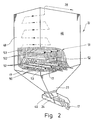
- Fig. 2 einen Bunker zur Neutralisation des Abgases in einem Rohstoffgemenge in perspektivischer Darstellung, und
- Fig. 3 einen Querschnitt durch den mit dem Glasscherbengemenge gefüllten Bunker gemäß der Fig. 2.
- 1 is a system diagram for performing the method according to the invention,
- 2 a perspective view of a bunker for neutralizing the exhaust gas in a raw material mixture, and
- 3 shows a cross section through the bunker filled with the broken glass batch according to FIG. 2.
Das erfindungsgemäße Verfahren wird nachfolgend anhand einer Anlage zur Glasherstellung beschrieben.The method according to the invention is described below using a plant for glass production.
Die in Fig. 1 gezeigte Anlage verfügt über eine Glasschmelzwanne 10, die in ihrem Deckengewölbe 11 Brenner 12 zum Erhitzen der in der Glasschmelzwanne 10 befindlichen Glasschmelze 13 aufweist. Die Brenner 12 werden üblicherweise gespeist durch zwei abwechselnd betriebene Regeneratoren 14, die öl- oder gasbefeuert sind.The system shown in FIG. 1 has a
Die Abgase aus der Glasschmelzwanne 10 werden wiederum durch die abwechselnd betriebenen Regeneratoren 14 geleitet zur Vorwärmung frischer Verbrennungsluft. Die Abgasleitungen 15 beider Regeneratoren 14 werden zu einem Steuerventil 16 geführt, von wo aus eine Weiterleitung der Abgase in einer weiter unten beschriebenen Weise erfolgt.The exhaust gases from the
Zur Bildung der Glasschmelze 13 wird der Glasschmelzwanne 10 ein Rohstoffgemenge 17 zugeführt. Dieses setzt sich zusammen aus einem Gemenge (frischer) Rohstoffe für die Glasherstellung und Altglas, nämlich insbesondere Glasscherben 20. Der Anteil der Glasscherben 20 bzw. eines Glasscherbengemenges, kann bis zu 90 % des Rohstoffgemenges 17 betragen.A
Einem Zwischenbunker 18 werden hier zur Bildung des Rohstoffgemenges 17 das (frische) Gemenge 19 und die Glasscherben 20 zugeführt. Dabei kann im Zwischenbunker 18 eine Vermischung des Gemenges 19 mit den Glasscherben 20 erfolgen. Das dabei entstehende, weitestgehend homogene Roh stoffgemenge 17 wird dann über eine Kette mehrerer in der Fig. 1 schematisch dargestellter Förderer 21 zur Oberseite eines dem Zwischenbunker 18 nachgeordneten Bunkers geleitet, der hier als Vorwärmbunker 22 ausgebildet ist. Diesen weiter unten anhand der Fig. 2 und 3 näher erläuterten Vorwärmbunker 22 verläßt das vorgewärmte Rohstoffgemenge 17 an einem unteren Auslauftrichter 23, aus dem das Rohstoffgemenge 17 über einen weiteren Förderer 24 in die Glasschmelzwanne 10 gelangt.The (fresh)
Erfindungsgemäß werden die aus den Regenatoren 14 kommenden Abgase von Steuerventil 16 aus über eine Zuführleitung 25 in den unteren Bereich des Vorwärmbunkers 22 geleitet. In aufsteigender Richtung, nämlich im Kreuz-Gegenstrom, wird das Abgas in mehreren Etagen (Kanalebenen) durch den Vorwärmbunker 22 geleitet, wobei das Abgas im oberen Bereich den Vorwärmbunker 22 wieder verläßt.According to the invention, the exhaust gases coming from the
Beim Durchströmen des Vorwärmbunkers 22 durch das Abgas erfolgt zum einen eine Neutralisation des Abgases, indem vorzugsweise bei der Verbrennung in der Glasschmelzwanne 10 im Abgas entstehende Schadstoffkomponenten, nämlich HCL, HF, SO₂, SO₃, CO und NOx, ganz oder zumindest soweit reduziert werden, daß der noch verbleibende Anteil dieser Schadstoffkomponenten unter den gesetzlichen vorgeschriebenen Grenzwerten liegt. Des weiteren erfolgt eine Abkühlung des Abgases bei der Hindurchströmung durch den Vorwärmbunker 22 von einer zwischen 400° - 500° C liegenden Eingangstemperatur auf eine Ausgangstemperatur von etwa 140° - 180° C. Das von oben nach unten allmählich durch den Vorwärmbunker 22 hindurchgeleitete Rohstoffgemenge 17 wird hierbei durch die Abgase von Raumtemperatur auf etwa 250° - 300° C vorgewärmt.When flowing through the preheating
Die aus dem Vorwärmbunker 22 austretenden Abgase können durch entsprechende Steuerventile 27 in der Zufuhrleitung 25, in einer Ableitung 28 für die Abgase aus dem Vorwärm bunker 22 und einer Verbindungsleitung 29 zwischen der Zufuhrleitung 25 und der Ableitung 28 so gesteuert werden, daß die Abgase unter Umgehung des Vorwärmbunkers 22 direkt ableitbar sind, falls eine kurzfristige Betriebsstörung im Vorwärmbunker 22 eintreten sollte. Des weiteren ist im vorliegenden Ausführungsbeispiel der Zufuhrleitung 25 eine Bypassleitung 30 zugeordnet, die unterhalb der Zufuhrleitung 25 im Vorwärmbunker 22 mündet und die ein Gebläse 31 zum druckbeaufschlagten Einleiten des über die Bypassleitung 30 in den Vorwärmbunker 22 gelangenden Abgases ermöglicht zur Aufrechterhaltung einer Aufrechtströmung der Abgase im Vorwärmbunker 22.The exhaust gases emerging from the
Die endgültige Abfuhr entsprechend neutralisierter und abgekühlter Abgase erfolgt bei geschlossenem Steuerventil 27 in der Verbindungsleitung 29 über die Ableitung 28 zu einem sich daran im vorliegenden Ausführungsbeispiel anschließenden Kühler 32. In diesem erfolgt eine weitere Abkühlung der Abgase, indem diese im Kühler 32 mit Wasser oder chemische Zusätze enthaltendem Wasser berieselt werden. Das Wasser wird dabei durch eine Umwälzpumpe 34 in einem geschlossenem Wasserkreislauf 33 (strichpunktiert) durch ein zur Abkühlung des im Kühler 32 aufgeheizten Wassers dienendes Reservoir 35 umgewälzt. Insbesondere dient der Kühler 32 auch zur vollständigen Abkühlung der bei Betriebsstörungen im Vorwärmbunker 22 kurzzeitig direkt über die Verbindungsleitung 29 und die Ableitung 28 zum Kühler 32 geleiteten (heißen) Abgase. In diesem Falle kann durch chemische Zusätze im Wasser des Kühlers 32 ersatzweise die dann nicht im Vorwärmbunker 22 erfolgende Neutralisation der Abgase durchgeführt werden.The final removal of appropriately neutralized and cooled exhaust gases takes place when the
Vom Kühler 32 aus gelangen schließlich die Abgase zu einer Elektrofilteranlage 37. Diese besteht im vorliegenden Ausführungsbeispiel aus drei hintereinander angeordneten Elektrofiltern 38, 39, 40 an sich bekannter Bauart. In diesen Elektrofiltern 38..40 erfolgt eine (Trocken-)Aus scheidung von kleinen Feststoffpartikeln in den Abgasen. Insbesondere handelt es sich hierbei um kleinste Scherbenpartikel aus dem Vorwärmbunker 22, die beim Hindurchleiten der Abgase durch denselben mitgerissen werden.From the
Durch unterschiedliche elektrische Felder in den einzelnen Elektrofiltern 38..40 erfolgt - wie sich überraschend gezeigt hat - eine Abscheidung von Feststoffpartikeln (Staub) aus den Abgasen, derart, daß Feststoffpartikel mit unterschiedlichen Eigenschaften, insbesondere chemischer Zusammensetzung, an bestimmten Elektrofiltern 38, 39 bzw. 40 abgeschieden werden.Due to different electric fields in the individual
Im vorliegenden Ausführungsbeispiel ist den drei Elektrofiltern 38, 39 und 40 eine Rückführleitung 42 (gestrichelt) zugeordnet, durch die die ausgeschiedenen Feststoffpartikel (Staub) zurückgeführt werden können, und zwar im vorliegenden Ausführungsbeispiel zum Förderer 24, der auch zur Abgabe des aus dem Vorwärmbunker 22 abgezogenen vorgewärmten Rohstoffgemenges 17 zur Glasschmelzwanne 10 dient.In the present exemplary embodiment, the three
Den Elektrofiltern 38..40 nachgeschaltet ist hier ein Saugzuggebläse 43, das die erfindungsgemäß behandelten Abgase mit Überdruck durch eine Rückführleitung 42 in einen entsprechenden Kamin 44 leitet, durch den die Abgase der Atmosphäre zuführbar sind.Downstream of the
Der Fig. 1 ist noch zu entnehmen, daß oberhalb des Steuerventils 16 von der Zufuhrleitung 25 des Abgases zum Vorwärmbunker 22 eine weitere Bypassleitung 45 abzweigt, die über ein zwischengeschaltetes weiteres Saugzuggebläse 46 direkt in dem Kamin 44 mündet. Hierdurch ist es möglich, den Glasschmelzprozeß in der Glasschmelzwanne 10 kurzfristig weiterzubetreiben, wenn aus irgendwelchen Gründen eine Ableitung der Abgase durch den Vorwärmbunker 22 nicht möglich ist. Gesteuert wird diese Umleitung der Abgase durch entsprechende Steuerventile 47 in der Zufuhrleitung 25, der Bypassleitung 45 und der Rückführleitung 42.1 also shows that a
Die Fig. 2 zeigt detailliert den Vorwärmbunker 22, der - wie sich gezeigt hat - sich besonders zur Durchführung des erfindungsgemäßen Verfahrens eignet. Demnach verfügt der Vorwärmbunker 22 über einen etwa quadratischen Querschnitt aus vier aufrechten Seitenwänden 48. Im unteren Bereich ist der Vorwärmbunker 22 trichterförmig verengt zum Auslauf 49 hin. Im Hauptteil des Vorwärmbunkers 22 befindet sich eine Vielzahl horizontaler Strömungskanäle 50. Diese befinden sich in übereinanderliegenden, horizontalen Kanalebenen 51. Im vorliegenden Ausführungsbeispiel sind acht Kanalebenen 51 aus jeweils drei Strömungskanälen 50 im Vorwärmbunker 22 gebildet. Dabei sind die Strömungskanäle 50 der angrenzenden Kanalebenen 51 versetzt zueinander angeordnet, liegen nämlich auf "Lücke". Dadurch sind die Strömungskanäle 50 annähernd gleichmäßig auf den Innenraum des Vorwärmbunkers 22 verteilt. Verbunden sind die Strömungskanäle 50 durch im Inneren des Vorwärmbunkers 22 angeordnete Überströmkanäle 52, die hier aus mit den entsprechenden Seitenwänden 48 verbundenen V-Profilen bestehen.2 shows the preheating
Jeder Strömungskanal 50 ist im vorliegenden Ausführungsbeispiel etwa gleich ausgebildet, und zwar in besonders einfacher Weise aus einem länglichen, gleichschenkligen Winkelprofil 53. Wie besonders deutlich die Fig. 3 zeigt, ist die Anordnung der Winkelprofile 53 für die Strömungskanäle 50 derart getroffen, daß die beiden gleichlangen Schenkel 54 unter einem gleichen Winkel liegen, nämlich unter ca. 45°, wobei eine Scheitelkante 55 oben liegt. Die beiden parallelen, unteren freien Kanten 56 der Schenkel 54 liegen damit etwa in einer horizontalen Ebene, nämlich der Kanalebene 51. Aufgrund dieser Ausbildung und Anordnung der Strömungskanäle 50 im Vorwärmbunker 22 bilden sie ein Dach für das Rohstoffgemenge 17, unter dem sich ein Schüttkegel im Rohstoffgemenge 17 ausbildet. Somit entstehen, wie ebenfalls die Fig. 3 anschaulich zeigt, Strömungskanäle 50 mit etwa quadratischem Querschnitt, wobei die Begrenzungsflächen der unteren Hälfte jedes Strömungskanals 50 unmittelbar durch das Rohstoffgemenge 17 gebildet wird. Dadurch ist ein optimaler Stoffübergang zwischen den durch die Strömungskanäle 50 geleiteten Abgasen und dem Rohstoffgemenge 17 zur Herbeiführung einerseits der Reduktion der Abgase und andererseits der Vorwärmung des Rohstoffgemenges 17 gegeben.Each
In der Fig. 3 ist ferner durch Pfeile 57 die abwärts gerichtete Fließrichtung des Rohstoffgemenges 17 im Vorwärmbunker 22 dargestellt. Demnach umströmt das Rohstoffgemenge 17 gleichmäßig längs eines etwa S-förmigen Verlaufs die Strömungskanäle 50 unterschiedlicher Kanalebenen 51. Dabei wechseln diejenigen Anteile des Rohstoffgemenges 17, die die unteren Begrenzungsflächen der Strömungskanäle 50 bilden ständig ab, was sich fördernd auf eine homogene Vorwärmung des Rohstoffgemenges 17 und eine zuverlässig Reduktion der Abgase auswirkt, da diese stets mit "frischem" Rohstoffgemenge 17 in Kontakt geraten.In FIG. 3,
Claims (13)
dadurch gekennzeichnet, daß die Abgase durch ein wenigstens teilweise aus Altglas (Glasscherben 20) bestehendes Rohstoffgemenge (1 7) geleitet werden.1. A method for treating exhaust gases from glass production, in particular for neutralizing smoke gases from a glass melting tank (10),
characterized in that the exhaust gases are passed through a mixture of raw materials (1 7) consisting at least partially of waste glass (broken glass 20).
Applications Claiming Priority (2)
| Application Number | Priority Date | Filing Date | Title |
|---|---|---|---|
| EP87112624 | 1987-08-29 | ||
| EP87112624 | 1987-08-29 |
Publications (2)
| Publication Number | Publication Date |
|---|---|
| EP0305584A2 true EP0305584A2 (en) | 1989-03-08 |
| EP0305584A3 EP0305584A3 (en) | 1989-09-20 |
Family
ID=8197234
Family Applications (1)
| Application Number | Title | Priority Date | Filing Date |
|---|---|---|---|
| EP87114467A Withdrawn EP0305584A3 (en) | 1987-08-29 | 1987-10-03 | Process for the treatment, especially for the neutralization of waste gases |
Country Status (1)
| Country | Link |
|---|---|
| EP (1) | EP0305584A3 (en) |
Cited By (7)
| Publication number | Priority date | Publication date | Assignee | Title |
|---|---|---|---|---|
| EP0395789A1 (en) * | 1989-03-28 | 1990-11-07 | BETEILIGUNGEN SORG GMBH & CO. KG | Process for the purification of waste gases emitted from a melting furnace |
| EP0552660A1 (en) * | 1992-01-20 | 1993-07-28 | AVIR FINANZIARIA S.p.A. | Process for the purification of waste gases emitted from melting furnaces |
| EP1123903A2 (en) * | 2000-01-18 | 2001-08-16 | The BOC Group plc | Electrostatic batch preheater |
| WO2011085711A1 (en) * | 2010-01-18 | 2011-07-21 | Rolf Wenning | Device and method for furnace pressure stabilization with changing volumetric amounts of flue gas when changing firing during glass melting and refining processes in transverse-fired furnaces with regenerative heating units |
| WO2012048706A3 (en) * | 2010-09-26 | 2012-06-21 | Get Glass Engineering Gmbh | Method and device for feeding in process waste gases and for controlling the waste gas volume in order to improve the furnace pressure stabilization in glass melting and refining processes in transverse-fired furnaces having regenerative heating units |
| CN104797537A (en) * | 2012-11-15 | 2015-07-22 | 旭硝子株式会社 | Method for producing alkali-free glass |
| CN109721223A (en) * | 2018-12-24 | 2019-05-07 | 郑州旭飞光电科技有限公司 | A kind of method and system producing liquid-crystalline glasses |
Citations (5)
| Publication number | Priority date | Publication date | Assignee | Title |
|---|---|---|---|---|
| US4042667A (en) * | 1974-07-25 | 1977-08-16 | Asahi Fiber Glass Company Limited | Method of cleaning waste gas containing a fluorine component |
| US4410347A (en) * | 1981-03-31 | 1983-10-18 | Ppg Industries, Inc. | Glass melting method using cullet as particulate collection medium |
| DE3416317A1 (en) * | 1984-05-03 | 1985-11-07 | Himly, Holscher GmbH & Co, 3070 Nienburg | Process and device for preheating raw materials for glass production, in particular a batch of glass fragments |
| EP0233647A1 (en) * | 1986-02-20 | 1987-08-26 | Grünzweig + Hartmann Aktiengesellschaft | Method and apparatus for melting siliceous raw materials, especially for the manufacturing of mineral wool |
| DE3631729A1 (en) * | 1986-09-18 | 1988-03-24 | Gea Luftkuehler Happel Gmbh | Process for the catalytic conversion of nitrogen oxides in the flue gases arising in glass manufacture |
-
1987
- 1987-10-03 EP EP87114467A patent/EP0305584A3/en not_active Withdrawn
Patent Citations (5)
| Publication number | Priority date | Publication date | Assignee | Title |
|---|---|---|---|---|
| US4042667A (en) * | 1974-07-25 | 1977-08-16 | Asahi Fiber Glass Company Limited | Method of cleaning waste gas containing a fluorine component |
| US4410347A (en) * | 1981-03-31 | 1983-10-18 | Ppg Industries, Inc. | Glass melting method using cullet as particulate collection medium |
| DE3416317A1 (en) * | 1984-05-03 | 1985-11-07 | Himly, Holscher GmbH & Co, 3070 Nienburg | Process and device for preheating raw materials for glass production, in particular a batch of glass fragments |
| EP0233647A1 (en) * | 1986-02-20 | 1987-08-26 | Grünzweig + Hartmann Aktiengesellschaft | Method and apparatus for melting siliceous raw materials, especially for the manufacturing of mineral wool |
| DE3631729A1 (en) * | 1986-09-18 | 1988-03-24 | Gea Luftkuehler Happel Gmbh | Process for the catalytic conversion of nitrogen oxides in the flue gases arising in glass manufacture |
Non-Patent Citations (1)
| Title |
|---|
| SPRECHSAAI, Band 120, Nr. 5, Mai 1987, Seiten 390-395, Coburg, DE; J. LEIMK]HLER et al.: "Abgasreinigung für Glasschmelzöfen" * |
Cited By (12)
| Publication number | Priority date | Publication date | Assignee | Title |
|---|---|---|---|---|
| EP0395789A1 (en) * | 1989-03-28 | 1990-11-07 | BETEILIGUNGEN SORG GMBH & CO. KG | Process for the purification of waste gases emitted from a melting furnace |
| EP0552660A1 (en) * | 1992-01-20 | 1993-07-28 | AVIR FINANZIARIA S.p.A. | Process for the purification of waste gases emitted from melting furnaces |
| AU657025B2 (en) * | 1992-01-20 | 1995-02-23 | Avir Finanziaria S.P.A. | Process for the purification of waste gases emitted from melting furnaces |
| EP1123903A2 (en) * | 2000-01-18 | 2001-08-16 | The BOC Group plc | Electrostatic batch preheater |
| EP1123903A3 (en) * | 2000-01-18 | 2001-11-14 | The BOC Group plc | Electrostatic batch preheater |
| AU772030B2 (en) * | 2000-01-18 | 2004-04-08 | Boc Group Plc, The | Electrostatic batch preheater |
| WO2011085711A1 (en) * | 2010-01-18 | 2011-07-21 | Rolf Wenning | Device and method for furnace pressure stabilization with changing volumetric amounts of flue gas when changing firing during glass melting and refining processes in transverse-fired furnaces with regenerative heating units |
| WO2012048706A3 (en) * | 2010-09-26 | 2012-06-21 | Get Glass Engineering Gmbh | Method and device for feeding in process waste gases and for controlling the waste gas volume in order to improve the furnace pressure stabilization in glass melting and refining processes in transverse-fired furnaces having regenerative heating units |
| CN104797537A (en) * | 2012-11-15 | 2015-07-22 | 旭硝子株式会社 | Method for producing alkali-free glass |
| CN104797537B (en) * | 2012-11-15 | 2017-03-08 | 旭硝子株式会社 | The manufacture method of alkali-free glass |
| CN109721223A (en) * | 2018-12-24 | 2019-05-07 | 郑州旭飞光电科技有限公司 | A kind of method and system producing liquid-crystalline glasses |
| CN109721223B (en) * | 2018-12-24 | 2021-11-26 | 郑州旭飞光电科技有限公司 | Method for producing liquid crystal glass |
Also Published As
| Publication number | Publication date |
|---|---|
| EP0305584A3 (en) | 1989-09-20 |
Similar Documents
| Publication | Publication Date | Title |
|---|---|---|
| EP0437679B1 (en) | Process for the treatment of ash in incinerator plants and an incinerator plant for this process | |
| DE2724372C2 (en) | Process for conditioning bypass gases | |
| EP1582251A1 (en) | Process and apparatus for flue gas cleaning | |
| EP0233647B1 (en) | Method and apparatus for melting siliceous raw materials, especially for the manufacturing of mineral wool | |
| EP0305584A2 (en) | Process for the treatment, especially for the neutralization of waste gases | |
| EP0324454B2 (en) | Process and apparatus for cleaning smoke | |
| DE3605100C2 (en) | ||
| DE4301353C1 (en) | Method of vitrifying waste material contg. high proportion of carbon - with heat generated by burning gases used to heat up material fed to appts. | |
| DE3520819A1 (en) | Process for the thermal treatment of masses contaminated with pollutants and plant for carrying out such a process | |
| DE3133467C2 (en) | Process for preheating glass batches in a heat exchanger | |
| DE2737117A1 (en) | METHOD AND DEVICE FOR CONTINUOUS REGENERATING OF USED CATALYST | |
| EP0211977B1 (en) | Process and apparatus for preheating raw material for glass production, especially cullet | |
| DE3416317A1 (en) | Process and device for preheating raw materials for glass production, in particular a batch of glass fragments | |
| EP2248773A1 (en) | Device for pre-heating batch containing cullet | |
| CH678401A5 (en) | METHOD AND DEVICE FOR Heat Treatment of fine-grained. | |
| DE19651691C2 (en) | Method and device for melting glass with simultaneous exhaust gas purification | |
| EP0654017A1 (en) | Thermal treatment process and device for waste and/or residual materials. | |
| DE4141625A1 (en) | METHOD FOR MELTING SILICATIC RAW MATERIALS, ESPECIALLY FOR THE PRODUCTION OF MINERAL WOOL, AND DEVICE FOR PREHEATING THE RAW MATERIAL BLOCK | |
| DE2232258C3 (en) | Process for the treatment of exhaust gases from industrial plants containing harmful components | |
| DE3340655A1 (en) | Filter apparatus for exhaust gas or water filtration | |
| DE4027529C1 (en) | Prodn. of chloro:silicate(s) - includes cleaning gases produced in thermal treatment of chloro:silicate(s) and feeding to waste gas burning unit | |
| EP0222078A2 (en) | Process and plant for producing aggregate for concrete from washery tailings | |
| DE4028112C2 (en) | ||
| EP0272465B1 (en) | Process and device for the separation and/or reaction of particles | |
| DE2605003A1 (en) | PROCESS FOR MANUFACTURING FIBER RUNNING, FIBER WILES OR MATS FROM THERMOPLASTIC MATERIAL, SUCH AS GLASS |
Legal Events
| Date | Code | Title | Description |
|---|---|---|---|
| PUAI | Public reference made under article 153(3) epc to a published international application that has entered the european phase |
Free format text: ORIGINAL CODE: 0009012 |
|
| AK | Designated contracting states |
Kind code of ref document: A2 Designated state(s): AT BE CH DE ES FR GB GR IT LI LU NL SE |
|
| PUAL | Search report despatched |
Free format text: ORIGINAL CODE: 0009013 |
|
| RHK1 | Main classification (correction) |
Ipc: C03B 5/235 |
|
| AK | Designated contracting states |
Kind code of ref document: A3 Designated state(s): AT BE CH DE ES FR GB GR IT LI LU NL SE |
|
| STAA | Information on the status of an ep patent application or granted ep patent |
Free format text: STATUS: THE APPLICATION IS DEEMED TO BE WITHDRAWN |
|
| 18D | Application deemed to be withdrawn |
Effective date: 19900502 |